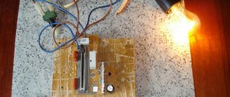
Recently, “out of production necessity,” I was looking for a circuit for a homemade power regulator, and made the device itself. I was quite pleased with the result, and then I’ll tell you how to make a power regulator with your own hands.
Source ytimg.com
A little about the triac power regulator and how to use it
Triac power regulators, which should now be called dimmers, have flooded our radio market.
Today, such devices can be found even in departments selling distillers, because dimmers are sometimes used to regulate the heating temperature of the material in distillation apparatuses.
These power regulators are also used in electric heaters for water tanks, incubators, vulcanizers for sealing car tubes, in tools - soldering irons for smoothly adjusting heating, in drills and grinders for controlling rotation speed, in simple incandescent lamps for adjusting brightness and even in moonshine stills.
In short, there are a huge number of ways to use power regulators; dimmers are very useful in economic and technical activities and are necessary devices for every workshop.
Source electronoff.ua
How does the process of voltage regulation occur in a distillation apparatus?
At the initial stage, turn on the heater at full power.
After reaching the temperature (78.8) degrees, which corresponds to the boiling point of ethyl alcohol, we reduce the heater power. By experimentally changing the position of the regulator, you need to ensure that all the released steam is condensed by the cooling system. This will help to avoid unnecessary losses of alcohol and at the same time, with correctly selected power, will reduce production time to the minimum possible. Voltage regulator
What does its power depend on?
Next we will talk about the nuances, of which there are only three, and on which the power of a dimmer, both factory and homemade, can depend.
The first nuance is the power reserve of the triac.
It should be about 30% for high-quality work, and the difference in their price will be insignificant.
For example, we can take a standard situation - you order a triac from a seller, who, in turn, will claim that its power reaches 4 kW.
At the same time, he will use various tricks, for example, he will take a close-up photo to deceive the eye and the heat sink will appear larger than it actually is.
Of course, if you turn on such a dimmer for half a minute, it can and will withstand it.
However, usually incandescent lamps or heating elements are connected to it, which work for hours at this power.
Such regulators will not withstand it, even at 3 kW they will heat up to the maximum, and then they will simply burn out.
You must understand what 40 kW is, and also that the regulator will have to pass 18 amperes through itself and what cross-section the wires must have in order to pass such a current.
The second nuance was touched on a little in the last paragraph, but still - the cross-section of the wires is more expensive than the printed circuit board.
The wider and thicker the cross-section of wires and tracks, the better, and the shorter the tracks and wires themselves, the better.
When soldering them, you must tin them with tin or solder a copper core along the tracks.
Additionally, if you are working with a device of 3,000 W or more, then it is better to abandon the various clamp terminals and any connectors.
After all, these places become vulnerable areas - if the contact weakens a little, then they heat up, and then the wires burn, which, of course, is undesirable.
Source stroykadoma.org
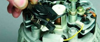
The third nuance is the heat sink.
If the heat sink for your home-made dimmer is not large enough, then after long-term use the entire device will become extremely hot (the temperature can reach 90 degrees Celsius and higher), it will be a real oven.
Therefore, I advise you to use a radiator from a computer with a cooler as a heat sink.
Such replacements for the heat sink, even small ones, will show good results during long-term operation at a power of 4,000 W, while Chinese radiators in the heat sinks will allow the device not to fail in the next few minutes after starting at such power.
Additionally, I’ll tell you a little about glass fuses.
Briefly about the main thing! I do not advise.
I somehow brought the fuse holder with a cap to the rear panel, set the fuse to 15 amperes, the load was about 3 kW.
As a result, the entire assembly became so hot that you couldn’t touch it with your hand.
Therefore, it is better to install automatic switches instead of glass fuses (if the load is 3,000 W, then a 16-amp switch).
Source evse.com.ua
Recommendations
If you do not have experience and knowledge of how to handle electrical appliances, then it is best not to touch them. If the wiring is incorrect, the network can receive a short circuit, as a result of which this device, as well as several others that were connected to the network, burned out.
Using the services of professionals significantly saves time and money, which you would still have to spend on a specialist if you did everything yourself. During the work, you can ask a professional about the manipulations being carried out.
He will tell you in detail what and how to connect and connect. Will share tips and tricks, conduct a practical lesson with devices.
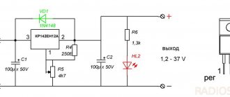
Power regulator circuit
The main control element is the BTA06-600 triac, which is also a triac.
You can replace it with almost any triac from the BTA series, for example BTA12-60, BTA24-600 and others.
In this case, it is possible not to recalculate the nominal values of the elements.
When buying a triac, keep in mind that the first numbers are the maximum current that it passes in the open state.
The second group of numbers is the maximum reverse voltage of this triac.
For example, let’s take the BTA06-600 triac - it turns out that its current is 6 amperes and the voltage is 600 V.
It is enough to adjust a device whose load will be 800 W.
Source motronix.co.il
I also advise you to take a current reserve when choosing a triac - changes in price will be insignificant, but the reliability of the design will increase.
The power of resistor R1 should be 0.25 W so that even when using a 3000 W regulator, the resistor will be cold.
There are no special requirements for a variable resistor, so you can take any one you like.
Capacitor C1 must be film and with a voltage of 400 V.
The fuse should be selected depending on the load current.
The LED can not be installed in the circuit, but then instead of the VD1 diode you will have to install a jumper.
Fuse F1 can be installed on a separate block or on the wire itself, with the cap of its housing located on the rear panel of the device.
Regulator for powerful heater
On the pages of the magazine “Radio” and in other amateur radio literature, many different designs of power regulators are described, from simple ones based on a single thyristor to rather complex ones with microcontroller control. However, the vast majority of designs of these regulators use a phase method for controlling output thyristors, so such regulators inevitably create impulse noise, the intensity of which increases with increasing load power.
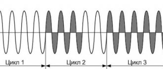
To control loads that have significant inertia, such as electric heaters, another method of power control is more suitable - changing the number of full periods of mains voltage passing through the load. This method, unlike the phase method, allows the output thyristors to open at the very beginning of each half-cycle of the mains voltage, which significantly reduces the level of interference created by the power regulator.
An additional advantage of this method is the possibility of using a triac solid-state optoelectronic relay as an output switching element, which contains a detector for the network voltage zero crossing. Such relays are controlled by constant voltage and allow switching currents of tens and hundreds of amperes, so an output node built using a solid-state relay is relatively simple.
The power regulator described in [1] operates on the principle of changing the number of half-cycles of the mains voltage passing through the load, and a modified version of this design, described in [2], allows you to control power by changing the number of full periods of mains voltage passing through the load, which eliminates the appearance of a constant component of the current flowing through the load. Both designs of regulators are built using two CMOS structure microcircuits, and power regulation is carried out in ten steps by changing the division coefficient of the counter, the input of which receives pulses at the network frequency.
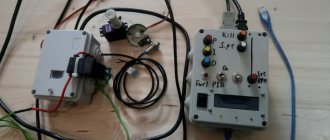
When the author needed a regulator for a 4 kW electric heater, the choice fell on the design described in [2], but the device circuit was redesigned taking into account the available parts. The result was a regulator built on a single chip and having sixteen stages of power control. A triac solid-state relay is used as an element that switches the load power circuit, and the elements of the regulator control device do not have a galvanic connection with the 230 V network.
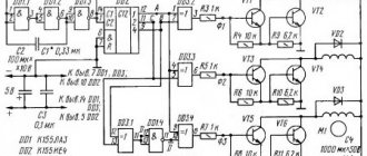
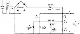
Rice. Regulator circuit
The regulator diagram is shown in the figure. During each positive (relative to the neutral wire) half-cycle of the mains voltage, current flows through the emitting diode of the optocoupler U1, so the phototransistor of the optocoupler opens at the beginning and closes at the end of each positive half-cycle, forming almost rectangular pulses at the input C2 (pin 2) of the DD1.1 counter, the next ones with a frequency of 50 Hz. As each pulse falls, the DD1.1 counter increases its state by one, and a binary code is formed at its outputs, corresponding to the number of calculated full periods of the mains voltage. After the 16th pulse arrives at the input, the counter overflows and the counting of pulses begins again.
The DD1.2 counter works as an RS trigger and ensures that the number of full periods of mains voltage required for the set power level is passed into the load. After each overflow of the DD1.1 counter, a voltage drop is formed at the C2 input (pin 10) of the DD1.2 counter, as a result of which the DD1.2 counter increases its state by one and is self-blocking by applying a high logical level to the C1 input (pin 9) from output Q1. The voltage at this output opens the field-effect transistor VT1, the drain circuit of which includes the emitting diode of the triac solid-state relay U2, which supplies mains voltage to the load. When a high logical level counter DD1.2 appears at input R (pin 15), it returns to its original state, the field-effect transistor closes and the load is disconnected from the network.
Switches SA1-SA4 are used to set the power allocated to the heater. Each of the switches connected through an isolation diode to the corresponding output of the meter DD1.1 has its own weight, corresponding to the number of full periods of mains voltage supplied to the load as a percentage of the total power. If only switch SA1 is closed, the load will receive only one of the sixteen periods of mains voltage, which corresponds to 100/16 or 6.25% of the full load power. When switch SA2 is closed, two out of sixteen periods will be supplied to the load, i.e. 12.5% of the power, and when several switches are turned on simultaneously, the power will be determined by the total weight of these switches. Thus, the device provides 16 stages of load power regulation, starting from 0 (all switches are open) and up to 93.75% (all switches are closed) in steps of 6.25%.
The regulator works as follows. With each overflow of the counter DD1.1, the counter DD1.2 goes into the single state at output Q1 and turns on the solid-state relay U2, which remains on for the number of full periods of the mains voltage specified by switches SA1 - SA4. When the outputs of counter DD1.1 reach a binary number corresponding to the power level set by switches SA1-SA4, a high logical level appears at pin 15 of counter DD1.2 and the trigger built on this counter returns to its original state, turning off the solid-state relay. The next time counter DD1.1 overflows, the trigger switches again to the single state, and the process repeats.
Diode VD6 is used to ensure correct operation of the regulator at a set power of 50%. The fact is that if only switch SA4 is turned on, the drop in the high logical level at pin 10 of counter DD1.2 will coincide with the drop in the high logical level at its reset input, so the counter DD1.2 will not be able to switch and the power on the load will be zero. The presence of the VD6 diode ensures that a low logical level appears at the R input of the DD1.2 counter immediately after the reset signal passes, thereby ensuring correct operation of the counter at a set power of 50%.
Switch SA5 is used to control the operating mode. In the “Regulator” position, the negative terminal of the solid state relay U2 is connected to the output of the power regulator, in the “Off” position. the load is turned off, and in the “Full power” position, the load receives all the mains voltage and the regulator does not work. By the frequency of flashes of the HL1 indicator LED, you can roughly judge the amount of power supplied to the load. Capacitors C2-C4 suppress noise at the corresponding inputs of the DD1 microcircuit, capacitor C1 is a blocking capacitor in the power circuit of this microcircuit.
The device is powered by a stabilized voltage of 5 V coming from the output of the switching power supply A1 (a charger for a cell phone model WTCS2 with a load current of up to 700 mA is used). To power the device, you can also use any suitable stabilized source with an output voltage of 5...14 V and a load current of at least 50 mA, increasing the resistance of resistors R1, R3, R5 in proportion to the value of the supply voltage. In the case when the power source is located at some distance from the regulator board, an oxide capacitor with a capacity of 220 μF for a rated voltage of 16 V should be connected in parallel with capacitor C1.
The device can use resistors of any type, but the power of resistor R2 must be at least 1 W. Non-polar capacitors - K10-7V or K10-17, diode VD1 - with a permissible reverse voltage of at least 400 V, the rest of the diodes - any low-power rectifier or pulse, for example, the KD521 or KD522 series. Instead of the K561IE10 microcircuit, you can use the imported MC14520 microcircuit, the 2N7000 field-effect transistor can be replaced with transistors BS170, KP501, or use a bipolar transistor of the npn structure, for example KT315 or KT3102, increasing the resistance of resistor R4 to 5.6 kOhm. Transistor optocoupler U1 - any with an insulation voltage of at least 1000 V, switches SA1-SA5 - any suitable in size.
The BDH-25044.ZD3 solid-state relay used by the author is controlled by a constant voltage of 3.32 V and is capable of switching current up to 250 A with an active load. For load currents up to 5 A, this relay can be used without a heat sink, and for higher currents, the relay should be installed on a heat sink using heat-conducting paste. In place of U2, you can also use any solid-state relay with a null detector and the required load current, or use a unit based on a triac optocoupler and two thyristors, as was done in [2]. If the regulator is used to control an inductive load, you should follow the recommendations given in the technical documentation of the solid-state relay used, and, if necessary, use surge protection elements (damping RC circuits or varistors).
In the author’s version, the device was made “in a hurry”, and a cardboard box was used as the housing of the control unit. The device showed reliable operation. When assembled correctly and from serviceable parts, the power regulator begins to work immediately and does not require adjustment. If there are no pulses at the output of the regulator (LED HL1 does not light or lights constantly), the resistance of resistor R2 should be reduced, achieving stable opening of the phototransistor of the optocoupler U1. If necessary, the brightness of LED HL1 can be changed by selecting resistor R5, and if indication is not necessary, the LED and this resistor can be excluded.
Using the described regulator, you can control the power of not only a single-phase, but also a three-phase load by installing a three-phase solid-state relay (necessarily with a null detector) in place of the U2 optorelay. The author conducted experiments with a three-phase heater with a power of 15 kW (heating elements are connected in a star with a midpoint output), using a solid-state relay HT-12044.ZD3. However, when using this method of regulation, it should be remembered that an integer number of periods of the mains voltage passes only through the phase to which the mains voltage control circuit is connected (optocoupler U1), therefore, in the other two phases, the appearance of a direct current component is inevitable, which negatively affects the operating mode networks.
When setting up and operating a power regulator, it should be taken into account that some of its elements are under mains voltage, so safety regulations must be observed. To protect the regulator from a short circuit, install a circuit breaker or fuse with a rated current equal to or slightly higher than the current consumed by the load in its power supply circuit (in the phase wire).
Literature
1. Lukashenko S. Power regulator that does not create interference. - Radio, 1987, No. 12, p. 22, 23.
2. Moroz K. Improvement of the power regulator. - Radio, 2014, No. 5, p. 30, 31.
Author: A. Melnikov, Barnaul
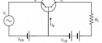
Circuit operation
During connection, the triac VD4 is closed, and current flows through fuse F1 and resistors R1, R2, while capacitor C1 is charged.
As soon as the voltage on capacitor C1 rises to 32 V, dinistor VD3 opens, through which current will flow, opening triac VD4.
The triac will pass the load current through itself and will close as soon as the sine wave passes zero potential.
After which the whole cycle repeats.
Source stoppanic.ru
Security measures
The entire process of assembling a homemade power regulator must occur strictly according to the diagram and instructions while observing safety rules.
The dimmer operates at a high voltage of 220 volts; for safety reasons, do not touch the device with a tool, much less with your bare hands.
However, know that the flange and, accordingly, the triac does not generate current - this has been tested from personal experience.
The performance of the dimmer should be checked on incandescent lamps with a power of 60 to 80 W.
It is not recommended to connect energy-saving, LED or other lamps in which starting devices and pulse converters are included.
Adjustment
It is worth understanding that the adjustment of the device does not depend on the shape of the input signal. Based on the type of placement, devices are divided into stationary and mobile.
- The differences are obvious, the first type is securely attached to a specific place.
- The second option, on the contrary, has the ability to be in any place where it is convenient for the master.
The voltage regulation device is currently an electrical circuit, thanks to which it becomes possible to regulate the voltage in a particular building if everything is connected correctly.
A little about cooling
For cooling, oddly enough, a cooling radiator is required.
It should be attached to the flange of the control element, and a layer of heat-conducting paste should be applied between them.
It is necessary to select the surface area of the radiator through trial and error.
From experience, I must say that if your homemade dimmer is installed on a soldering iron, incandescent lamp or other object with a power of up to 80 W, then you can do without a radiator.
If the regulator is used in a device whose controlled load power reaches 1000 W, then a radiator with an area of 200 square centimeters will be required; during long-term operation (5 hours), such a radiator heated up to 90 degrees Celsius.
Well, for long-term work with a 3 kW load, I took the same radiator, and installed an additional fan-cooler from the computer to cool the processor, which was powered by a miniature rectifier. At the same time, the radiator temperature was room temperature.
Source prom.st
I recommend the following video, in which the author independently makes a power regulator with his own hands:
As a result…
Making a homemade power regulator for a 3 kW heating element is not difficult. You can verify this yourself, having at the same time a basic set of technical skills and abilities, as well as design components. Use the diagram above to make such a useful device that can be used in many devices, for example, electric heaters, incubators, vulcanizers, soldering irons, drills, grinders, just incandescent lamps and much more.
Question
Write in the comments what do you think is a better and more reliable regulator – homemade or factory-made?