The fundamental relationship in electricity is the relationship between current and voltage. Thanks to this law, experimentally established by Ohm in 1826, various measuring instruments were created. It was possible to study the physics of short circuits. The formula can be applied to systems that depend on electrical resistance. Perhaps the development of any electrical network is impossible without using this discovery.
Current value
By definition, current strength is a physical quantity equal to the amount of charge q passing through the cross section of the conductor during time t:
If the current strength does not depend on time, then such an electric current is called constant. Let us further consider just such a case when the current is constant. It is extremely difficult to measure the amount of charge, so in 1826 the German physicist Georg Ohm did the following: in an electrical circuit consisting of a voltage source (battery) and resistance, he measured the amount of current at different resistance values. Then, without changing the resistance value, he began to change the parameters of the voltage source, connecting, for example, two or three sources at once. By measuring the current in the circuit, he obtained the dependence of the current on the voltage U and on the resistance R.
Rice. 1. Current and voltage measurement circuit by Georg Ohm.
Determination of electrical voltage
That is, the electric field had to “pull” electrons through the load, and the energy that was consumed in this case is characterized by a quantity called electrical voltage. The same energy was spent on some change in the state of the load substance. Energy, as we know, does not disappear into nowhere and does not appear from nowhere. This is stated by the Law of Conservation of Energy. That is, if the current spent energy passing through the load, the load acquired this energy and, for example, heated up.
That is, we come to the definition: the voltage of an electric current is a quantity that shows how much work the field did when moving a charge from one point to another. The voltage in different parts of the circuit will be different. The voltage on a section of an empty wire will be very small, and the voltage on a section with any load will be much greater, and the magnitude of the voltage will depend on the amount of work done by the current. Voltage is measured in volts (1 V). To determine the voltage there is a formula:
U=A/q,
where U is the voltage, A is the work done by the current to move the charge q to a certain section of the circuit.
Ohm's law
As a result of his research, Georg Ohm discovered that the ratio of the voltage U between the ends of a metal conductor, which is part of an electrical circuit, to the current strength I in the circuit is a constant value:
where R is electrical resistance. This formula is called Ohm's law, which is still the main calculation tool in the design of electrical and electronic circuits.
If we plot the voltage values along the abscissa axis, and the current values in the circuit at given voltage values along the ordinate axis, we will get a graph of the dependence of the current I on the voltage U.
Rice. 2. Graph of current versus voltage.
From this graph it is clear that this relationship is linear. The angle of inclination of the straight line depends on the amount of resistance. The larger R, the smaller the angle of inclination.
Rice. 3. Graph of current versus resistance.
If we fix the voltage U and plot the values R of the electrical resistance along the abscissa axis, then the resulting graph shows that this dependence is already nonlinear - with increasing resistance, the behavior of the current is described by an inversely proportional function - a hyperbola.
Ohm's law stops working at high current values, as additional effects associated with thermal heating of the substance and an increase in temperature begin to operate. In gases at high currents, breakdown occurs, the current grows like an avalanche, deviating from the linear law.
Volt-ampere characteristics
With its help, you can find out how the current changes when the voltage in the circuit increases or decreases. If it is built for a conductor, the dependence will be linear. This can be understood from Ohm's law, according to which the force is proportional to the applied potential difference. This type of graph is typical for metals. But at the same time, for semiconductors it will not be linear.
The thing is that such materials have special properties. A breakdown may occur in them - a phenomenon in which a sharp increase in current strength and a saturation process occur. In the latter case, the value of the electric current practically does not change with increasing voltage.
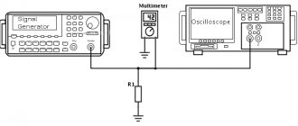
The dependence graph is constructed in a Cartesian coordinate system. The X axis represents voltage, and the Y axis represents current. You can study the characteristics for any circuit element yourself. To do this you will need to prepare:
- adjustable power supply;
- ammeter;
- voltmeter;
- element under study.
The circuit is assembled quite simply. A current meter (ammeter) is connected to the power supply, to the output of which a conductor is connected with one terminal. The second pole is connected to the free contact of the voltage source. The voltage meter is connected in parallel to the element being tested.
The experiment is as follows. Using the power supply, the voltage is changed, the value of which is read from the voltmeter. At the same time, data is written off from the ammeter. Then the coordinate axes of the current-voltage characteristics are drawn, on which the points of the corresponding quantities are plotted and connected by a smooth line. The drawn curve or straight line will display the real picture of the dependence of current on voltage for the element. Using the current-voltage characteristic, you can plot the dependence of power on current. To do this, you need to perform a calculation using the formula: P = I*U.
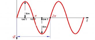
In practice, we often have to deal with alternating current. This is a phenomenon in which its strength changes over time. In this case, the current-voltage characteristic is not used, since the change in U occurs according to a certain law, most often sinusoidal, therefore, if you need to plot a graph of voltage versus time, you need to know the formula with which the function is described.
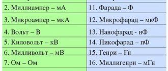
Units
In the International System of Units (SI), the unit of electrical resistance is called the “ohm” in honor of the physicist Georg Ohm. By definition, an electrical resistance of 1 ohm has a section of the circuit where the voltage drops 1 V at a current of 1 A.
The unit of measurement of resistivity is derived from the units of quantities included in the formula: resistance, length and area. That is, in the SI system it turns out that if R = 1 Ohm, S = 1 m 2, and L = 1 m, then ρ = 1.
This is the unit of measurement for resistivity. But in practice it turned out that real wires have a cross-sectional area much less than 1 m2. Therefore, when calculating ρ, it was decided to use the value of the area S in mm 2 so that the final value has a compact form. Then we get more convenient (fewer zeros after the decimal point) numerical values of resistivity for perception:
General information
Any physical body consists of molecules and atoms. These particles interact with each other. They can attract each other or repel each other. In an isolated system, elementary particles are charge carriers. In a quiet state, that is, when there is no external influence on the body, the algebraic sum of the particle energy is always a constant value. This statement is called the law of conservation of electric charge.
Particles can move randomly along the crystal lattice, but their movement is compensated. Therefore, no current occurs. But if an external force is applied to the body, then the free electrons begin to move in one direction. This ordered movement of charged particles is called electric current. It can be quantitatively described through force.
Ordered charges are forced to move by an electric field, along the lines of which movement occurs. This term was first introduced by Faraday. He was able to find out that around any carrier there is a special type of matter that affects the behavior of other particles. The force characteristic of the electric field was taken to be the ratio of the acting force to the magnitude of the charge placed at a given point: E = F / q. We called this characteristic tension.
The study of the field made it possible to experimentally discover the principle of superposition. That is, to establish that the field strength created by a system of charges is equal to the geometric sum of the values existing for individual carriers: E = Σ E1 + E2 +…+ En. Tension is directly proportional to voltage, which in turn is equal to the potential difference between two points.
Essentially, this is the work done by an electric field to transfer a unit charge from one place to another: U = A / q = E * d, where d is the distance between points. The voltage value depends on several factors:
- body structure;
- temperature;
- resistance.
The last value has the greatest influence. It characterizes the ability of a material to prevent the passage of current, that is, it determines conductivity. Resistance depends on the length of the conductor and its cross-section: R = (p * l) / S, where p is the inverse parameter of conductivity (reference value). It is numerically equal to the resistance of a homogeneous conductor of unit length and cross-sectional area.
What have we learned?
So, we have learned that the dependence of the current in an electrical circuit is described using Ohm's law. The current strength I is directly proportional to the voltage value U, and inversely proportional to the resistance R.
The figure shows a graph of current versus time in an electrical circuit with an inductance of 1 mH.
Determine the module of the average value of the self-induction emf in the time interval from 10 to 15 s.
The magnitude of the self-induction EMF is proportional to the rate of change of current in the circuit and inductance:
Since the current in the circuit did not change in the time interval from 10 to 15 s, we obtain that the modulus of the average value of the self-induction emf in this time interval is zero.
The figure shows the moment of a demonstration experiment to test Lenz's rule, when all objects are motionless. The south pole of the magnet is inside the solid metal ring, but does not touch it. The rocker arm with metal rings can rotate freely around the vertical support. When the magnet moves out of the ring to the left, the ring will
1) stay still
2) move to the right
3) oscillate
4) move after the magnet
As the magnet moves out of the ring to the left, the magnetic flux from it through the ring begins to decrease. An induced current occurs in the ring. According to Lenz's rule, the direction of the current is such that the magnetic field it creates prevents the magnetic flux from changing. Since the rocker arm can freely rotate around a vertical axis, and the magnetic field of the magnet is non-uniform, the rocker arm will begin to move under the action of Ampere forces in such a way as to prevent a change in the magnetic flux, that is, the rocker arm will begin to move after the magnet.
Relationship between parameters
For electric current to appear, several conditions must be met. We need a source of it, a material that has free charge carriers, and a closed circuit through which they can move. After the invention of the “voltaic column,” scientists began to conduct various experiments studying the flow of electric current. In 1825, Ohm, in his experiments using a galvanic source and torsion balances, observed the loss of energy in charges. He discovered that the current in a circuit depends not only on the type of material, but also on its linear characteristics.
Analyzing the data obtained, Ohm derived the formula: X = a*k/L, where: X is the electric current, a is the electrical voltage, k is the conductivity coefficient, l is the length of the material. Subsequently, this law was confirmed by other scientists and was named after the discoverer.
In its modern form it is written as follows: I = U/R, where:
- U—potential difference (voltage);
- R - resistance.
That is, the current strength in a conductor is directly proportional to the voltage and inversely proportional to its resistance. R is the proportionality coefficient. By its definition, it is the reciprocal of conductivity. Resistance depends on the physical dimensions of the conductor and its ability to prevent the passage of electric current.
The value of R can be calculated using the formula: R = pL/S, where p is the specific coefficient depending on the property of the material, L is the length of the conductor, S is the cross-sectional area. The resistivity value depends on temperature, but remains constant for each degree. Its value has been measured for almost all existing elements in nature and is tabulated.
Open formulas made it possible to establish not only the dependence of current on resistance, but also to connect 2 fundamental electrical quantities - force and work. Moreover, the relationship between them is usually depicted using a graph called the current-voltage characteristic. Its meaning is to construct a function described by Ohm's law. This is an important graph for electrical devices. Using it, you can determine the power for any value.