Ideally, in order to check the windings of an electric motor, it is necessary to have special instruments designed for this, which cost a lot of money. Surely not everyone has them in their home. Therefore, it is easier for such purposes to learn how to use a tester, which has another name: a multimeter. Almost every self-respecting home owner has such a device.
Electric motors are manufactured in various versions and modifications, and their malfunctions are also very different. Of course, not every fault can be diagnosed with a simple multimeter, but most often checking the motor windings with such a simple device is quite possible.
Any type of repair always begins with an inspection of the device: the presence of moisture, whether parts are broken, the presence of a burning smell from the insulation and other obvious signs of malfunction. Most often, the burnt winding is visible. Then no checks and measurements are needed. Such equipment is immediately sent for repair. But there are times when there are no external signs of failure, and a thorough check of the motor windings is required.
Types of windings
If you don’t go into details, the motor winding can be imagined as a piece of conductor that is wound in a certain way in the motor housing, and it seems that nothing should break in it.
However, the situation is much more complicated, since the electric motor winding has its own characteristics:
- The material of the winding wire must be uniform along its entire length.
- The shape and cross-sectional area of the wire must have a certain accuracy.
- In industrial conditions, a layer of insulation in the form of varnish must be applied to the wire intended for winding, which must have certain properties: strength, elasticity, good dielectric properties, etc.
- The winding wire must provide strong contact when connected.
If there is any violation of these requirements, then the electric current will flow under completely different conditions, and the electric motor will deteriorate its performance, that is, the power, speed will decrease, and may not work at all.
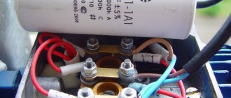
Checking the motor windings of a 3-phase motor . First of all, disconnect it from the circuit. The majority of existing electric motors have windings connected in star or delta configurations.
The ends of these windings are usually connected to blocks with terminals that have the appropriate markings: “K” - end, “N” - beginning. There are options for internal connections, the nodes are located inside the motor housing, and different markings (numbers) are used on the terminals.
The stator of a 3-phase electric motor uses windings that have equal characteristics and properties, and the same resistance. When measuring the winding resistances with a multimeter, it may turn out that they have different values. This already makes it possible to assume that there is a malfunction in the electric motor.
Possible faults
It is not always possible to visually determine the condition of the windings, since access to them is limited by the design features of the engine. In practice, you can check the winding of an electric motor using its electrical characteristics, since all motor breakdowns are mainly detected:
- A break, when the wire is broken or burnt out, no current will pass through it.
- A short circuit caused by damaged insulation between the input and output turns.
- A short circuit between turns, with the insulation damaged between adjacent turns. As a result, damaged turns are self-excluded from operation. Electric current flows through the winding, which does not involve damaged turns that do not work.
- By breaking through the insulation between the stator housing and the winding.
Methods
Checking the motor windings for open circuits
This is the simplest type of verification. The malfunction is diagnosed by simply measuring the wire resistance value. If the multimeter shows very high resistance, then this means that there is a wire break with the formation of air space.
Checking the motor windings for short circuits
If there is a short circuit in the motor, its power will be cut off by the installed short circuit protection. This happens in a very short time. However, even in such a short period of time, a visible defect in the winding may occur in the form of carbon deposits and metal melting.
If you measure the winding resistance with instruments, you get a small value that approaches zero, since a piece of the winding is excluded from the measurement due to a short circuit.
Checking the motor windings for interturn short circuits
This is the most difficult task in identifying and troubleshooting. To check the motor winding, several measurement and diagnostic methods are used.
Checking the motor windings. Malfunctions and test methods
Ideally, in order to check the windings of an electric motor, it is necessary to have special instruments designed for this, which cost a lot of money.
Surely not everyone has them in their home. Therefore, it is easier for such purposes to learn how to use a tester, which has another name: a multimeter. Almost every self-respecting home owner has such a device. Electric motors are manufactured in various versions and modifications, and their malfunctions are also very different. Of course, not every fault can be diagnosed with a simple multimeter, but most often checking the motor windings with such a simple device is quite possible.
Any type of repair always begins with an inspection of the device: the presence of moisture, whether parts are broken, the presence of a burning smell from the insulation and other obvious signs of malfunction. Most often, the burnt winding is visible. Then no checks and measurements are needed. Such equipment is immediately sent for repair. But there are times when there are no external signs of failure, and a thorough check of the motor windings is required.
Types of windings
If you don’t go into details, the motor winding can be imagined as a piece of conductor that is wound in a certain way in the motor housing, and it seems that nothing should break in it.
However, the situation is much more complicated, since the electric motor winding has its own characteristics:
- The material of the winding wire must be uniform along its entire length.
- The shape and cross-sectional area of the wire must have a certain accuracy.
- In industrial conditions, a layer of insulation in the form of varnish must be applied to the wire intended for winding, which must have certain properties: strength, elasticity, good dielectric properties, etc.
- The winding wire must provide strong contact when connected.
If there is any violation of these requirements, then the electric current will flow under completely different conditions, and the electric motor will deteriorate its performance, that is, the power, speed will decrease, and may not work at all.
Checking the motor windings of a 3-phase motor . First of all, disconnect it from the circuit. The majority of existing electric motors have windings connected in star or delta configurations.
The ends of these windings are usually connected to blocks with terminals that have the appropriate markings: “K” - end, “N” - beginning. There are options for internal connections, the nodes are located inside the motor housing, and different markings (numbers) are used on the terminals.
The stator of a 3-phase electric motor uses windings that have equal characteristics and properties, and the same resistance. When measuring the winding resistances with a multimeter, it may turn out that they have different values. This already makes it possible to assume that there is a malfunction in the electric motor.
Possible faults
It is not always possible to visually determine the condition of the windings, since access to them is limited by the design features of the engine. In practice, you can check the winding of an electric motor using its electrical characteristics, since all motor breakdowns are mainly detected:
- A break, when the wire is broken or burnt out, no current will pass through it.
- A short circuit caused by damaged insulation between the input and output turns.
- A short circuit between turns, with the insulation damaged between adjacent turns. As a result, damaged turns are self-excluded from operation. Electric current flows through the winding, which does not involve damaged turns that do not work.
- By breaking through the insulation between the stator housing and the winding.
Methods
Checking the motor windings for open circuits
This is the simplest type of verification. The malfunction is diagnosed by simply measuring the wire resistance value. If the multimeter shows very high resistance, then this means that there is a wire break with the formation of air space.
Checking the motor windings for short circuits
If there is a short circuit in the motor, its power will be cut off by the installed short circuit protection. This happens in a very short time. However, even in such a short period of time, a visible defect in the winding may occur in the form of carbon deposits and metal melting.
If you measure the winding resistance with instruments, you get a small value that approaches zero, since a piece of the winding is excluded from the measurement due to a short circuit.
Checking the motor windings for interturn short circuits
This is the most difficult task in identifying and troubleshooting. To check the motor winding, several measurement and diagnostic methods are used.
Checking the motor windings using an ohmmeter
This device operates on direct current and measures active resistance. During operation, the winding forms, in addition to active resistance, a significant inductive resistance value.
If one turn is closed, then the active resistance will practically not change, and it is difficult to determine it with an ohmmeter. Of course, you can accurately calibrate the device, carefully measure all windings for resistance, and compare them. However, even in this case it is very difficult to detect shorted turns.
The results are much more accurately produced by the bridge method, which measures active resistance. This method is used in a laboratory environment, so ordinary electricians do not use it.
Current measurement in each phase
The phase current ratio will change; if a short circuit occurs between the turns, the stator will heat up. If the engine is fully operational, then the current consumption is the same in all phases. Therefore, by measuring these currents under load, we can confidently say about the actual technical condition of the electric motor.
Checking motor windings with alternating current
It is not always possible to measure the total winding resistance and take into account the inductive reactance. For a faulty motor, you can check the winding with alternating current. For this, an ammeter, a voltmeter and a step-down transformer are used. To limit the current, a resistor or rheostat is inserted into the circuit.
To check the motor winding, a low voltage is applied and the current value is checked, which should not be higher than the nominal value. The measured voltage drop across the winding is divided by the current to obtain the total resistance. Its value is compared with other windings.
The same circuit makes it possible to determine the current-voltage properties of the windings. To do this, you need to take measurements at various current values, then write them down in a table or draw a graph. There should not be large deviations when comparing with other windings. Otherwise, there is an interturn short circuit.
Interturn closure of armature, stator, transformer. How to determine a short circuit between turns.
Electric motors often fail, and the main reason for this is interturn short circuit. It accounts for about 40% of all engine breakdowns. What causes a short circuit between the turns? There are several reasons for this.
The main reason is the excessive load on the electric motor, which is higher than the established norm. The stator windings heat up, destroy the insulation, and a short circuit occurs between the turns of the windings. By incorrectly operating an electric machine, an employee creates excessive load on the electric motor.
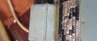
The normal load can be found in the equipment data sheet or on the motor plate. Excessive load may occur due to a breakdown of the mechanical part of the electric motor. Roller bearings may be the cause. They can jam due to wear or lack of lubrication, resulting in a short circuit in the armature coil turns.
Short circuits of turns also occur during repair or manufacturing of the engine, as a result of defects if the engine was manufactured or repaired in an unsuitable workshop. It is necessary to store and operate the electric motor according to certain rules, otherwise moisture may penetrate inside the motor, the windings will become damp, and as a result, a turn short circuit will occur.
With a turn short circuit, the electric motor does not work fully and does not last long. If the interturn short circuit is not detected in time, you will soon have to buy a new electric motor or a completely new electrical machine, for example, an electric drill.
When the motor winding turns are short-circuited, the excitation current increases, the winding overheats, destroys the insulation, and other winding turns are short-circuited. Due to an increase in current, the voltage regulator may fail. The turn circuit is determined by comparing the winding resistance with the standard according to the technical specifications. If it has decreased, the winding must be rewinded and replaced.
Which electric motors can be tested with a multimeter?
There are different modifications of electric motors, and the list of their possible malfunctions is quite large. Most problems can be diagnosed using a regular multimeter, even if you are not an expert in this field.
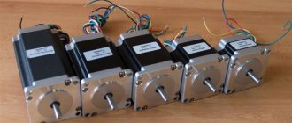
Modern electric motors are divided into several types, which are listed below:
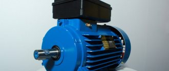
- Asynchronous, three phases, with a squirrel-cage rotor. This type of electric powertrain is the most popular due to its simple design that allows for easy diagnostics.
- Asynchronous capacitor, with one or two phases and a squirrel-cage rotor. Such a power plant is usually equipped with household appliances powered from a conventional 220V network, the most common in modern homes.
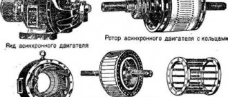
- Asynchronous, equipped with a wound rotor. This equipment has a more powerful starting torque than motors with a squirrel-cage rotor, and therefore it is used as a drive in large power devices (lifts, cranes, power plants).
- Collector, direct current. Such motors are widely used in cars, where they drive fans and pumps, as well as power windows and wipers.
- Collector, alternating current. These motors are equipped with hand-held power tools.
The first stage of any diagnosis is a visual examination. If burnt windings or broken parts of the motor are visible even with the naked eye, it is clear that further inspection is pointless and the unit must be taken to a workshop. But often an inspection is not enough to identify problems, and then a more thorough check is necessary.
Method No. 2 of checking the armature for a turn short circuit
This method is suitable for those who are not involved in professional repair of power tools. To accurately diagnose an interturn short circuit, a bracket with a coil is required.
Using a multimeter you can only find out if the armature coil is broken. It is better to use an analog tester for this purpose. We measure the resistance between each two lamellas.
The resistance should be the same everywhere. There are cases when the windings are not burned out, the collector is normal. Then the closure of the turns is determined only using a device with a bracket from the transformer. Now we set the multimeter to 200 kOhm, connect one probe to ground, and touch the other to each lamella of the collector, provided that there are no broken coils.
If the armature does not connect to ground, then it is serviceable, or there may be an interturn short circuit.
What faults in an electric motor can a multimeter detect?
Quite often, a multimeter, a multifunctional electronic measuring instrument, is used to test AC motors. It is available to almost every home craftsman and allows you to identify some types of faults in electrical appliances, including electric motors.
The most common malfunctions that occur in electrical machines of this type are:
- winding breakage (rotor or stator);
- short circuit;
- interturn closure.
Let's look at each of these problems in more detail and look at methods for identifying such faults.
Checking for breakage or integrity of the winding
Winding breakage is a fairly common occurrence when improper operation of an electric motor is detected. A break in the winding can occur in both the stator and the rotor.
If one phase in a winding connected according to a star circuit is broken, then there will be no current in it, and in other phases the current values will be overestimated, and the engine will not work. There may also be a break in the parallel phase branch, which will lead to overheating of the serviceable phase branch.
If one phase of the winding (between two conductors) connected in a delta circuit was broken, then the current in the other two conductors will be significantly less than in the third conductor.
If a break occurs in the rotor winding, current fluctuations will occur with a frequency equal to the frequency of slip and voltage fluctuations, while a hum will appear and the engine speed will be reduced, and vibration will also occur.
These reasons indicate a malfunction, but the malfunction itself can be identified by checking and measuring the resistance of each motor winding.
Determination of interturn short circuit
Turn-to-turn short circuit is determined by checking the resistance. This value is measured using a flaw detector or ohmmeter. The readings obtained are compared with the resistance present in a working winding.
If the resistance in the winding being tested is lower than in the reference winding, this indicates the presence of an interturn short circuit in it. If necessary, this malfunction can be determined using the induction method. To do this, the turns of the electrical winding being tested are in an alternating magnetic field, after which an electromotive force is induced.
When the winding has closed turns, it begins to heat up under the influence of induced currents. When even one or two turns are closed, heating occurs within 3 to 5 minutes.
The interturn short circuit of the stator winding can be determined by a flaw detector, without removing it from the grooves. The flaw detector includes induction and signaling devices located one behind the other in a common housing. The cores of both devices are simultaneously applied to the teeth of the grooves or along the length of the conductors of the winding being tested. The winding of the induction apparatus is connected to a network with a voltage of up to 18 volts. A magnetic field arises, causing the induction of an electromotive force.
When there is a turn circuit, current begins to flow through the winding, and its own magnetic field appears around the conductors. As a result, an electromotive force also appears in the winding of the signal apparatus, after which the signal lamp lights up.
How to check for breaks in windings
To quickly determine whether there is a break inside the windings, you need to place the multimeter probes at the beginning and end of each winding in diode continuity mode. If there is no sound, there is a break.
To determine the short circuit between the windings, you need to place probes at the beginning of the windings (V1-U1, V1-W1, U1-W1). And similarly check between the ends. If there are no problems, then there should be no calling.
You should also measure between the end of the first winding and the beginning of the second (V2-U1), and similarly with the end of the second and the beginning of the third (U2-W1), the end of the third and the beginning of the first (W2-V1). I'll explain why. If there is a break in some winding, then you will not see this malfunction by simply checking between the beginnings of the windings.
If you have only 3 pins in the box, then there should be a connection between them, since the connected star/delta circuit cannot be changed with jumpers in the box and everything is already connected inside. All that remains is to check the body and disassemble it for a visual assessment.
It is also worth checking the resistance in each winding by setting the multimeter switch to the minimum value (200 Ohms). It should be approximately equal for everyone. So we check the resistance between the turns. About him below.
Interturn closure of armature
To check the armature, we will use a special device, which represents a transformer with a cut-out core. When we place the armature in this gap, its winding begins to act as the secondary winding of a transformer. Moreover, if there is an interturn short circuit on the armature, the metal plate, which will be located on top of the armature, will vibrate or be magnetized to the armature body due to local oversaturation with iron.
We turn on the device. For clarity, we specially closed two lamellas on the collector to show how diagnostics are performed. We place the record on the anchor and immediately see the result. Our record became magnetized and began to vibrate. We turn the armature, the coils shift, and the plate stops vibrating.
Now let's remove the slat short circuit to check. We repeat the check and see that the armature winding is working properly, the plate does not vibrate in any places.
Winding insulation resistance measurement
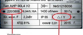
To test a motor for insulation resistance, electricians use a megger with a test voltage of 500 V or 1000 V. This device measures the insulation resistance of motor windings designed for an operating voltage of 220 V or 380 V.
For electric motors with a rated voltage of 12V, 24V, a tester is used, since the insulation of these windings is not designed for testing under the high voltage of 500 V megger. Typically, the motor data sheet indicates the test voltage when measuring the insulation resistance of the coils.
Insulation resistance is usually checked with a megger
Before measuring the insulation resistance, you need to familiarize yourself with the connection diagram of the electric motor, since some star connections of the windings are connected at a midpoint to the motor housing. If the winding has one or more connection points, delta, star, single-phase motor with starting and running windings, then the insulation is checked between any connection point of the windings and the housing.
If the insulation resistance is significantly less than 20 MΩ, the windings are disconnected and each is checked separately. For a complete motor, the insulation resistance between the coils and the metal casing must be at least 20 MΩ. If the motor has been operated or stored in damp conditions, then the insulation resistance may be below 20 MΩ.
Then the electric motor is disassembled and dried for several hours with a 60 W incandescent lamp placed in the stator housing. When measuring insulation resistance with a multimeter, set the measurement limit to the maximum resistance, megohms.
Homemade device for determining turn circuits
Let's make a choke with our own hands to check the interturn short circuit in the motor winding. We will need U-shaped transformer iron. It can be taken, for example, from the old vibration pump “Rucheek”, “Malysh”. We disassemble its lower part and heat it well. There are coils filled with epoxy resin.
We heat the epoxy and knock out the coils with the core. Using sandpaper or a grinder, we cut off the jaws of the core. These coils are wound just on the U-shaped transformer iron.
No need to respect angles. You need to make a place where a small and a large anchor can easily fall.
When processing, it is necessary to take into account that the iron is laminated. You cannot treat it in such a way that the stone lifts it. It is necessary to process in such a direction that the layers lie towards each other so that there are no scuffs. After processing, remove all chamfers and burrs, since you will have to work with enameled wire; it is not advisable to scratch it.
Now we need to make two coils for this core, which we will place on both sides. We measure the thickness and width of the core in the widest places, along the rivets. We take thick cardboard and mark it according to the size of the core. We take into account the size of the groove in the core between the coils. We run the non-sharp edge of the scissors along the bend points to make it easier to bend the cardboard. We cut out the blank for the coil frame. Fold along the fold lines. This creates the frame of the coil.
Now we make four covers for each side of the coils. We get two cardboard frames for the reels.
We calculate the number of turns of the coils using the formula for transformers.
13200: 7.56 = 1746 turns for two coils. This number is optional; a deviation of 10% in both directions will not play any role. Round up, 1800: 2 = 900 turns need to be wound on each coil. We have 0.16 mm wire, it will fit our coils just fine. You can wind it any way you like. 900 turns can be wound manually. If you make a mistake by 20-30 turns, then nothing bad will happen. Better to wind more. Before winding with an awl, we make holes along the edges of the frame for the output of the coil wires.
Important nuances
Experts have developed a universal device for checking interturn short circuits. But first of all, you need to accurately establish the fact that there is no additional load on the motor. The problem may occur due to a clogged air system or a stuck mechanical section. To accurately determine the interturn short circuit, it is necessary to observe the running engine for some time. In such a situation, the master will notice intense circular sparking. There may be an unpleasant odor of burnt insulation. To eliminate a problem, you need to identify it in a timely manner. Upon standard visual inspection, the armature windings should not be swollen or blackened. A burning smell may indicate a problem. The technician must make sure that there is no short circuit between the collector plates.
Electrician's recommendations
If, when the electric motor is running, you can clearly hear a squealing or creaking noise that was absent at low speeds, then the reason is obviously an insufficient amount of lubricant in the bearings, or they are heavily contaminated.
Also, a worn bearing is indicated by powerful vibration of the shaft, which rotates by inertia. This may indicate an imbalance in the fan wheel. It is possible that one of the blades broke off.
Important! If winding insulation violations are detected, it is better to repair the engine in special service centers.
If the situation requires diagnostics of the electric motor winding, then without having general concepts of electrical engineering, it is advisable to entrust this work to real professionals. This labor-intensive process requires not only work skills, but also the use of special equipment that will allow for high-quality repairs.
Expert opinion
Viktor Pavlovich Strebizh, lighting and electrical expert
Any questions ask me, I will help!
In 380 Volt motors connected according to a star or delta circuit, it will be necessary to disassemble the circuit and ring each of the three windings separately. If there is something you don’t understand, write to me!
DIY repair
To check the interturn short circuit on the armature, you need to carefully attach the lamp starter to the collector plate. You need to see whether the light comes on or not. If the light bulb works, then the technician needs to think about replacing the winding or the entire rotor. But if there is no reaction, the test must be performed with an ohmmeter. The resistance should be as low as possible, no more than 9 kOhm. If the short circuit is interturn, then a certain device will be useful for checking the starter armature. This problem can be eliminated if you align all the wires and clear them of excess debris. If all of the above recommendations do not work, all that remains is to rewind the armature. When unsoldering the collector terminals, it is necessary to dismantle the rotor and thoroughly clean the surface using a drill. A burnt-out battery can only be determined using a battery.
Stator interturn short circuit
Often a faulty motor has an interturn short circuit. First, check the stator winding for resistance. This is an unreliable method, since the multimeter cannot always accurately show the measurement result. This also depends on the motor rewinding technology and the age of the iron.
Clamps can also measure resistance and current. Sometimes they check by the sound of a running motor, provided that the bearings are in good condition, lubricated, and the drive gearbox is in good condition. They also check the turn-to-turn short circuit with an oscilloscope, but they are more expensive and not everyone has this device.
Externally inspect the engine. There should be no traces of oil, smudges, or smell. The current measured by phase must be the same. A good tester checks the windings for resistance. If the difference in measurements is more than 10%, there is a possibility of a short circuit in the winding turns.
Source
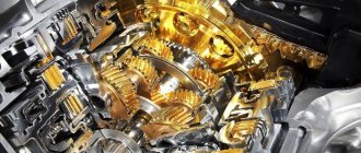
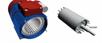
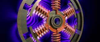
Design features
The design of electric motors can differ significantly, but it is often represented by a combination of similar elements. The moving element is usually called the rotor, the stationary element is called the starter. Copper wire can be wound as follows:
Multimeters are used to test various electrical equipment. On sale you can find various versions of this measuring device, they all have their own characteristics. The main selection criteria are the following:
- Pointer or digital dial. Digital is more in demand today, as it has a large number of different functions and high accuracy. Today, switch models are practically not found on sale.
- Functionality. The more functions, the wider the scope of application of the device. This increases the cost of the measuring device.
- The backlight and hold button for readings can improve the comfort of using the multimeter.
- The lower the operating error, the more accurate the tester. Most models have an error of no more than 3%.
- If professional provision of services is envisaged, then attention should be paid to a model with a high degree of protection from dust or moisture. The higher the degree of protection of the device, the longer it will last.
- Electrical safety class. All measuring instruments are divided into 4 classes, which determine the scope of application of the multimeter.
You can check the basic indicators of an electric motor using the simplest equipment.
Expert opinion
Viktor Pavlovich Strebizh, lighting and electrical expert
Any questions ask me, I will help!
This model is very popular because the device is simple and can be diagnosed using a conventional measuring tool. If there is something you don’t understand, write to me!