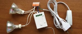
We take another piece of wire, enclose it in a corrugation and lead it to the main junction box.
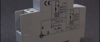
Place the wires into the terminals fig. Explanation of the connection diagram to simplify understanding Let us describe the connection diagram of a switch that works with one lighting device, in our case a light bulb.
It increases service life and minimizes the size of their flasks. ✅Connecting a one-key switch
Then you need to check the functionality again. If the connection comes out both long and flexible, fold it in half, pressing it with pliers.
The connected wires are neatly laid inside the junction box. Wiring diagram Connecting to the junction box Now begins the most exciting process - connecting your wiring to the junction box. No, we're checking the connections. The electrical wire to the light bulb placed on the ceiling runs through one of these gutters.
Connecting the socket and switch
Types of light switches
Household switching devices can be classified according to different criteria. First of all, they are divided by purpose. It is determined by the type of contact groups and their number. The most common devices are key ones. They have a contact group for closing and opening an electrical circuit. Based on the number of contact groups, such devices are divided into:
- single-key – with one contact group;
- two-key – with two independent groups;
- three-key - with three.
Designation of switches on diagrams and drawings.
There are also pass-through and crossover devices for creating light control schemes from several points.
Contact diagrams for various household appliances.
According to the method of influence they can be divided:
- keyboards;
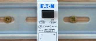
- push-button – with a non-latching button to control the light via pulse relays;
- rotary - to turn on the lighting, the control element must be turned;
- touch, remote controlled, etc. – to create systems such as “Smart Home”.
By type of installation, switches are divided into:
- external – used for open or hidden wiring;
- built-in – used for hidden wiring.
According to the degree of protection, switches are divided into devices for indoor installation and outdoor installation (IP no less than 44). Also, when choosing, you need to pay attention to the rated current - it should cover the current of the intended load with a margin.
Connecting LED strips and lamps
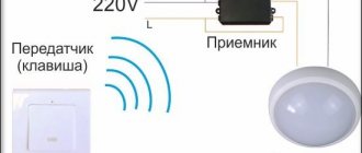
The connection diagram for LED-based illuminators is no different from the previously discussed options. The only thing you should pay attention to before connecting an LED strip or lamp is the use of a voltage converter (power supply) or driver.
As in the case of spotlights, in this situation the power supply is installed immediately after a single-key, two-key or three-key switch (photo below).
Each individual strip or LED device is connected through its own converter, which allows you to control its operation independently of the others. Several lighting strips can be connected to “powerful” adapters at once.
Preparing for work, choosing equipment
To successfully connect a light bulb, certain materials and tools are required. Without this, there is no need to talk about any quality that determines the durability of the system.
A set of necessary tools
To perform installation you will need:
- installer's knife for stripping insulation;
- if you have an insulation stripper, it will be useful for stripping individual conductors;
- To shorten cables and wires to the required length, you will need wire cutters;
- to install electrical appliances you will need a set of screwdrivers;
- if you plan to solder twists or tin the stripped sections of wires, you will need an electric soldering iron with a set of consumables (flux, solder).
During the work, you will also need other small plumbing tools (pliers, hammer, etc.).
Conductor Products
When choosing a cable for a lighting system, you should take it as a basic rule - no aluminum. The relative cheapness of aluminum conductor products is balanced by potential problems in further operation:
- the plasticity of this metal leads to deterioration of contacts in the clamping terminals; they will need to be periodically tightened;
- its fragility will lead to problems during subsequent repairs;
- the tendency to oxidize in air will also not improve the contact (copper is also not free from this drawback, but here the problem can be radically solved by tinning the stripped areas).
In addition, the resistivity of aluminum is 1.7 times higher than that of copper. Therefore, you will have to choose conductors with a larger cross-section. This also somewhat offsets the financial savings.
Post navigation
Advantages and disadvantages of the PV circuit from 2 places This switching circuit has advantages and disadvantages.
If we talk about the front side, the only difference is: a barely noticeable arrow on the up and down key. Then in both places it will be possible to turn on and off both the general lighting in the room and the lamps by the bed.
The opposite is also true. Two-key pass-through switch: connection diagram In order to control the lighting of two lamps or groups of lamps from one switch from several places, there are two-key pass-through switches.
For switches, exactly as shown in the figures, the input common terminal for phase or zero is located on one side of the case, and 2 output terminals are on the other. If you now press the key of the second switch and also change its position, the circuit will again be open and the lamp will go out. You can see the control diagram for lighting systems from three places in the following photo: A single-line connection diagram using this method looks like this: As can be seen from the above photo, the main difference in lighting control between control from 2 and 3 places is the presence of a cross switch and more connected wires in the junction box. What is the best cable to use for connecting pass-through switches? For this fitting, most experts agree that it is better to use a three-core copper cable with a cross-section of 1.
How to connect a pass-through switch - 3-place lamp control circuit
As you probably already understood, a single-pole pass-through switch has two fixed contacts and one changeover contact. How is a pass-through switch different from a regular one? In all of the above cases, pass-through switches are installed next to the doors. When a key is pressed, the moving contacts simultaneously switch from one pair of fixed contacts to another pair.
You go into the bedroom and turn on the light at the door. Four PVs are connected using crossover switches, as described above. The lighting control system most often considered is used in public and industrial premises, namely: in long corridors, tunnels, walk-through rooms, that is, in rooms where there are two doors equally serving as entrance and exit, in staircases and other places. Secondly, something else may be required, and this will become clear from the specific options for connecting devices.
Scope of application of pass-through switches Installation and connection of a pass-through switch will be useful when controlling lighting systems in the following cases: in the presence of large corridors or walk-through rooms; when controlling lighting fixtures at the entrance to the room and directly near the bed; when installing lighting in large industrial and industrial buildings; if necessary, control the lighting in the next room; in the presence of stairs connecting several floors in most cases in cottage premises, and so on. The main difference between the above wires is the type of insulation and the nature of the conductors. The schematic image shows that if the light is on, pressing any of the buttons will turn it off. Light control is carried out using switches: for one light source, an ordinary light bulb, or several lamps, there is one switch.
Rear view of pass-through switches of various types. The photo shows a rear view of electrical installation products. See the figure for how everything should be organized. Connecting a pass-through switch for lighting control from 3 places
Conductor markings
To perform electrical installation work, it is more convenient to use cables, all conductors of which are marked. It is performed using insulation of various colors. For three-core cables used in single-phase 220 volt networks, the color marking indicated in the table has become a kind of standard.
| Purpose of the conductor | Designation on diagrams | Color |
| Phase | L | Red, brown, white |
| Null | N | Blue |
| Protective | P.E. | Yellow-green |
Failure to comply with color matching will not lead to a disaster or loss of network functionality, but to confusion and installation errors - almost 100%.
A less common option is digital marking. Numbers from one to the maximum number of cores in the cable are applied to the insulation along the entire length of the conductor. If an unmarked cable is used, after laying and cutting it, you must call it using a multimeter or other method and mark the wires yourself.
Regular switch for one lamp
The figure below shows a diagram of connecting a light bulb to a regular light switch.
The switch is installed in a phase gap. Zero is directed to the lighting fixture. If you set the switch to zero, the contacts will soon burn out. The reason is the increased load when electricity passes through the zero contact.
Another reason for breaking a phase conductor is the need to quickly disconnect voltage from the consumer in the event of an emergency. Zero does not allow the system to be de-energized, but only opens the circuit.
Note! Electrical installation work should only be carried out in a de-energized electrical network. If it is not possible to determine the phase conductor by color scheme, it is allowed to supply current to carry out “ringing”. Before checking, you need to make sure that there are no short circuits in the exposed wiring.
Connection of copper and aluminum conductors
It is a well-known fact that conductors should not be in direct contact in electrical wiring. Copper and aluminum have a significant difference in electrochemical potential, so an EMF will occur at the point of their contact. It is insignificant, but over a long period of operation, the current constantly flowing through the joint will cause electrochemical corrosion when interacting with atmospheric moisture. It leads to the formation of an oxide film, poor contact and local overheating, and these effects will only increase over time. The result will be a burnout of the contact point, or even a fire of the insulation of conductors or other nearby objects.
Therefore, copper and aluminum wires can only be connected through terminals made of steel . Better yet, forget about the very possibility of making aluminum wiring and make it only from copper conductors.
Application
In everyday life, parallel connections are very common. For example, Christmas tree garlands, where all the light bulbs have maximum brightness.
By connecting, you can create interior lighting of any length. Replacing a burnt out element is easy. Two 60 W devices can be exchanged for one 10 W lamp without compromising the lighting parameters. This property of the circuit is used by experienced electricians to identify the phase in three-phase networks.
Halogen lamps and incandescent lamps not only produce a bright glow, but also heat the environment. For this reason, they are often used in garages, hangars or workshops for heating rooms. To do this, connect the devices to the network, placing them in a metal block. The design heats up to 60 degrees and maintains a comfortable room temperature. However, high powers lead to frequent lamp burnouts.
Related video: WHAT IS SERIAL AND PARALLEL CONNECTION
Parallel connection is used in strip lighting, chandeliers, and street lighting. Each lamp can be controlled separately, which increases the convenience of using the overall network. You just need to install the required number of switches into the system.
In houses and apartments, not only lighting devices, but also various equipment are connected to the network in parallel.
When creating lighting devices with LED elements, a mixed connection is often used based on a series circuit of loads, followed by a parallel connection to the same circuit.
We recommend watching: How to understand whether to connect lamps or loads in series or parallel
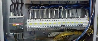
Selecting a junction box
If installation is carried out in a residential area, choosing a junction box comes down to purchasing a plastic box suitable for:
- external wiring;
- hidden wiring;
- installation on a plasterboard partition.
You also need to pay attention to the size - if you plan to make a large number of connections in one box, then the dimensions of the box should be increased.
But if the junction box is installed indoors with special conditions (manufacturing, etc.) or outdoors, then you need to pay attention to the degree of protection against moisture and dust IP, and select a product that meets the operating conditions.
A few words about electric current
Without “loading” with theory and complex physical concepts, let us recall the elementary basics of electrics. The household electrical network has a voltage of 220 V, the type of current is alternating. What does it mean? One of the contacts, “phase,” has a constantly changing potential from “+” to “−” (50 cycles per second), and the other “zero” serves as a kind of battery, allowing electrons to either accumulate in excess or flow back.
Each lamp has two contacts: base and central. In order for our lighting device to start working, zero and phase must be connected to these two contacts. Moreover, in the case of alternating current and a regular household lamp, polarity does not play any role.
But it is still necessary to know the location of “zero” and “phase”. There is a special device - a “probe”, which is used to determine which of the wires is phase. This must be kept in mind for the correct inclusion of a disconnecting device - a switch - in the circuit. It must necessarily break the “phase”, these are the safety requirements.
Wiring and making connections
The key point when connecting a lamp through any switch is the quality of the electrical connections. If this job is done poorly, everything else is meaningless.
Removing insulation
First of all, the cables must be shortened to the required length. This can be done using wire cutters. Next, remove the insulation in the desired areas.
The cable contains at least two layers of insulation:
- external – common to all conductors;
- internal - individual for each core.
Both layers can be removed with a mechanic's knife - cut the plastic along the ring, being careful not to touch the wires, and remove the resulting piece.
Removing external insulation with a knife.
It is even better to use special pullers for external and internal insulation.
Removing external insulation with a stripper.
Removing the insulation of the cores with a stripper.
Their advantage is that you can adjust the depth of the cut so as not to damage the wires. In addition, the wire looks neater after cutting.
Performing twisting
When disconnecting the wires in the junction box, you can use clamp terminals. But there is a reasonable opinion that this good, convenient and progressive method does not guarantee reliable contact for many years (especially at high currents), so the good old twisting will not leave the scene for a long time.
Before starting work, it is worth remembering once again that you cannot twist copper and aluminum conductors. It is possible to twist aluminum ones together, but the fragility of this metal imposes restrictions on this method. Therefore, it is optimal to twist copper conductors together. In addition, copper is easily soldered, so after twisting it is recommended to solder the contact point. This will protect the surface of the conductor from oxidation and give the connection mechanical strength.
Twisting after soldering.
Another option is to weld the ends of the twisted wires. To do this, you will need an industrial or homemade welding machine.
Twisting after welding.
Twisted wires can be crimped, but this will require copper sleeves, special tools and skills.
A set of materials and tools for crimping.
In any case, the twists must be insulated. In addition to electrical tape, special plastic caps are suitable. When using heat shrink, remember that the sharp ends of the wires can damage the applied thin tube. Therefore, it is advisable to use heat shrink in two layers.
Insulation of twists with heat shrink tube.
A good alternative to spring terminals and twisting is the use of screw terminal blocks. At the same time, the problem of contact between aluminum and copper is solved. But they take up more space in the distribution box and installation is more labor-intensive.
An example of connecting wires using Wago self-clamping terminal blocks.
Wall chipping
If you choose the option of hidden wiring, before starting installation you need to make channels in the wall for laying cable products - grooves (the term grooves is found in technical and regulatory literature). It is best to do them using a special power tool - a wall chaser. If you don’t have one, a grinder or hammer drill will do. As a last resort - a hammer and chisel.
The work is very dusty, so it is necessary to take measures to protect the respiratory system, as well as surrounding objects.
Several restrictions must be observed when working:
- grooves can be laid strictly horizontally or vertically (at an angle of 0 or 90 degrees);
- You cannot cut horizontal channels on load-bearing walls.
The remaining rules can be studied in SP 76.13330.2016 (current edition of SNiP 3.05.06-85).
Then, in pre-selected places, it is necessary to arrange recesses for installing distribution boxes and socket boxes. This is done using a core drill.
Switch installation
With open wiring, the switch is installed on a backing panel or directly on the wall.
Installation of surface-mounted switch.
If the built-in option is selected, the socket box is first mounted and the cable is routed into it.
Installation of socket box and cable outlet.
Next, the cable is cut as indicated above: it must be shortened and stripped of insulation.
Then you should remove the decorative parts from the switch - the frame and keys.
Switch with removed decorative elements.
Next you need to connect the wires to the terminals. If the terminals are clamping, then the cores are simply inserted into them. If they are screw-type, they must be securely tightened with a screwdriver.
Connecting wires to clamp terminals.
Next, tighten the bolts of the expansion petals until the device is completely fixed in the socket box and, if provided for by the design, attach it to the wall with self-tapping screws.
Fastening the switch with self-tapping screws.
After this, you can install the plastic parts back, apply voltage and test the operation of the circuit.
More detailed instructions for installing the switch are described in a separate article.
What's the end result?
If you thoughtfully approach the issue of connection, then such work will not pose any special difficulties. The main thing is not to neglect safety issues when carrying out electrical installation work. It must be remembered that all work is carried out only with the voltage turned off, because 220 volts is a dangerous current, the shock of which can lead to death or serious damage to the body.
If there is even the slightest doubt that self-installation is possible, it is better to seek help from a specialist. After all, if the quality of the connections is poor, the wiring may catch fire and, as a result, a fire in the house or apartment. Therefore, as they say, “measure twice, cut once.”
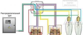
Connection using a junction box
Connection using a junction box is always recommended, with the exception of implementing a lighting control circuit from several points using sequential connection of pass-through and cross switches. In this case, it is better to lay cables and connect with a cable.
If installation with a junction box is chosen, it is carried out according to the following principles:
- a two-core power cable (three-core if there is a grounding conductor) with phase and neutral wires is laid from the switchboard to the box;
- each luminaire has its own two-core cable (three-core in TN-S or TN-CS ) with cores L and N ( PE );
- conductors N and PE follow in transit through the box to the lamps; if necessary, they are branched according to the number of lamps;
- the phase conductor has a break, a switching device is connected to it according to the diagram;
- A cable with the appropriate number of cores is lowered to the switch.
PE conductor must be laid, even if lamps without grounding are used (for example, with incandescent lamps). This will help avoid problems in the future when reconstructing the network.
We recommend that you see clearly how the masters do it.
Tools
The connected socket is installed in its socket box, where it is secured with mounting screws, after which it is checked with a level. Double pass-through switch A pass-through switch is needed in order to be able to control lighting from different places in two lighting lines, as, for example, shown in Fig. They are also connected with two wires and can replace simple single-key ones. Due to this, certain energy consumers are connected or disconnected at the right time. Stripping of insulation is carried out at a distance of mm from the edge of the core. Once again we twist the wires connecting the operating phases of the switch and the general network, having first turned off the power.
If you want to understand the types of switches in more detail, you can read the article Types of switches.
One of the cores serves to create a continuous network. In our case, it does not matter which electrical wire will be used, copper or aluminum. Fastening elements for laying wiring in wooden buildings. The distribution box is installed. The connection diagram is shown in the figure below. Connecting a single-key switch and socket. The easy way.
More on the topic: What are the technical requirements for insulation resistance
Connecting a switch with lamps connected in parallel
This connection has no fundamental differences from the usual one - the phase and neutral wires are drawn to the first lamp in the diagram, from there in a loop to the second, and so on. If one lamp burns out, the others will remain in operation. One has only to remember that in such a circuit the switch must be designed for the total current of all lamps .
Diagram of parallel connection of lamps.
Connection diagram for two light bulbs
Single key switch
Connecting two incandescent light bulbs to one switch is carried out according to the standard scheme, the only difference is in how the light sources themselves are connected. Using a switching device with one key, you can simultaneously control two lighting fixtures at once, no matter how they are connected to each other, in parallel or in series.
The main thing you need to remember is that it is recommended to place the breaking contact on phase, and the wire connected directly to the light bulb to zero. Otherwise, of course, the circuit will also work, but then when replacing a burnt-out light source, it becomes necessary to turn off the entire power supply to the room or area, since it is the potential traveling along the phase conductor that affects the human body. It is easy to determine the phase using a regular indicator screwdriver or tester.
Two-gang switch
If everything is clear about connecting two light bulbs to a single-key switch, let’s consider a switch with two keys and its operating and connection features. It has one common contact and two outgoing contacts going to a separate load. In this case, all installation must be performed through a junction box; this will further simplify the connection of new lighting fixtures or troubleshooting. The wiring to the switch is carried out with a three-wire wire, and the wiring to the lamps and the supply voltage input is carried out with a two-wire wire.
A double switching device can be used to separately control two light sources of any type, the main thing is, again, not to forget about the current limitation in the circuit. It is based on the current flowing in the lighting circuit that you need to select both the switch itself and the cross-section of the wire.
The video below clearly shows how to connect two lamps to a double switch:
Pass-through switches
Connecting two light bulbs to a pass-through switch is used when lighting long corridors and tunnels, and for this they must be used in pairs, otherwise the meaning of their use is lost. Here is a schematic diagram for such a connection. All installation must also be done through a junction box:
The whole essence of connecting two or more lamps to a pass-through switch is presented in the video:
Schematic connection examples
As a simple example, let’s look at what the circuit diagram for connecting a switch to one light bulb looks like (protective grounding available). A three-core cable runs from the switchboard into the box, and a three-wire cable also goes to the lamp. The phase conductor is broken; a switching device is connected to the gap using a two-core cable.
Diagram of wiring and connection of conductors for the option with a single switch.
A similar circuit with a triple switch and three lamps looks much more complicated. A larger number of connections are made in the box, so you need to choose a larger distribution box.
Scheme of laying and connecting conductors for the version with a triple device.
Installing a circuit with two lamps and two double pass-through switches in a box looks even more difficult. It is better to implement such a scheme using a cable.
Scheme of laying and connecting conductors for the option with two pass-through devices.
Obviously, the second option simplifies installation and reduces the consumption of cable products.
Layout of the cable and connection of conductors for the option with two pass-through devices.
General scheme of premises electrification
The general scheme of electrification of a room can be divided into two parts - powering consumers and providing lighting.
In the first case, everything is simple - wiring is thrown from the distribution board (if necessary, it is divided), thanks to which branches are created, and brought to the sockets, through which consumers are connected to the electrical network.
The sockets themselves are constantly energized after connection.
In the case of organizing room lighting, not everything is so simple, since it is necessary to create a branch that provides for the possibility of de-energizing lighting elements - light bulbs.
For this purpose, the circuit contains switches (switches), the task of which is, if necessary, to interrupt and restore the voltage supply circuit to the consumer.
For the normal functioning of indoor lighting and to ensure safety, there are certain schemes for connecting lighting devices through switches to the electrical network.
Moreover, there are several varieties, which allows you to organize the connection of light bulbs according to the provided layout.
For example, with just one switch you can control the lighting of several rooms, independently of each other.
Previously, they used switches that cut into the wiring. That is, the wiring was thrown directly from the distribution board to the light bulb socket, and then the phase core of the wire was cut in the right place, and a breaker was installed in this gap.
Errors and possible malfunctions
One of the main mistakes when connecting a switch is incorrect determination of the location of its terminals. Many people believe that by default a separately made terminal is always common. This is not true - manufacturers can arrange the terminals in any order . Therefore, before starting installation, it is necessary to determine the terminals of the device. This is easy to do if a diagram is applied to the device. If not, you can use a multimeter to test the internal connections. At the same time, this process will test the device for serviceability.
Another common mistake is incorrect connection of the conductors in the box. To reduce it to a minimum, it is necessary to use cables with marked cores. If the cores are single-colored, after laying and cutting the cables, you need to call them with a multimeter and mark them yourself.
Video lesson: 5 mistakes when disconnecting junction boxes.
Briefly about the main thing
The LED lamp is based on a semiconductor crystal. When current passes through it, light radiation is released. The main components of the device also include a driver, a radiator and a diffuser. The main advantages of an ice lamp are a long service life, economical energy consumption, harmlessness, durability, unpretentiousness, and a variety of lighting parameters. The disadvantage is the high price.
In the standard version, LED lamps are available in ratings of 220 and 12 volts; they can be connected either directly instead of conventional incandescent light bulbs or with fluorescent lamps according to the following schemes:
- Consistently.
- Parallel.
- Luchev.
In addition, there is a way to replace fluorescent lamps with ice tubes in the housing of old ballast models or new electronic analogues. Each case has its own characteristics and technical nuances.
Security measures
The main safety measure when installing wiring is to perform all actions with the voltage removed . If the lighting system is being made from scratch, then connecting the power wire to the circuit breaker is done last. If work is being carried out to reconstruct or repair an existing circuit, it is necessary to carry out technical measures:
- turn off the circuit breaker (or circuit breaker) of the lighting system;
- take measures to prevent spontaneous or erroneous switching on - disconnect the supply wire from the terminal of the machine;
- if the power supply system is made according to the TN-S principle, then the disconnected wire must be connected to the ground bus;
- check that there is no voltage on the phase wire.
Important! It is necessary to check the absence of voltage directly at the place of work - in the distribution box or at the switch terminals.
Labor safety rules when working in electrical installations also require the use of dielectric gloves, carpets, and insulated power tools. It is unlikely that anyone will have laboratory-tested protective equipment in their everyday life, but if possible, they should be used. There is no such thing as too much security. At the very least, you can monitor the insulation condition of hand tools visually. With this approach, the likelihood of electric shock during operation will be minimal, installation will be carried out accurately, quickly, and will last a long time and reliably.
How to properly connect a switch
In order to correctly connect electrical appliances, you must follow simple operating and safety rules:
- Never start work unless you are sure there is no voltage in the network;
- A neutral wire always comes to a chandelier or light bulb;
- The phase must always be supplied to the switching devices.
These conditions must be strictly observed if the light bulb needs to be replaced during operation.
An electrician, when replacing a lamp, if he accidentally touches live parts, will not be struck by an electric shock. Since phase voltage is not supplied to the lamp when the electrical switch is turned off.
Safety precautions when working with electrical wiring
The lamp is connected only after installing the switch. Its normal position is “Off”. Before starting work, the room is de-energized. If necessary, the entire building is switched off. After disconnection, a sign “Do not turn on!” is put on the switch. But even after this, before you grab the bare wire with your hand, check for the presence of current with a probe or, in extreme cases, with the back of your hand. Otherwise, muscle spasm will not allow you to unclench your fingers and release the cord.
It makes sense to use electrically insulated gloves, pliers and screwdrivers with insulated handles. If it is necessary to extend the wire from two pieces, the exposed parts are twisted tightly, and then the joint is carefully wrapped with insulating tape. You can use special connectors where the exposed areas are inserted into holes and then clamped with screws. Before connecting the light switch, download the circuit diagram from a trusted website. If you doubt your own competence, call an electrician.