Thyristor circuit
This converter has two stable states: closed (low conductivity state) and open (high conductivity state). The purpose of the thyristor is to perform the function of an electric switch, the peculiarity of which is the impossibility of independently switching to the closed state. The device performs the functions of an open circuit switch and a rectifying diode in DC networks. The main material in the production of this semiconductor device is silicon. The housing is made of polymer materials or metal - for models operating with high currents.
Thyristor design and applications
The device includes 3 electrodes:
- anode;
- cathode;
- control electrode
Unlike a two-layer diode, a thyristor consists of 4 layers - pnpn. Both devices pass current in one direction. On most older models, its direction is indicated by a triangle. External voltage is applied with a “-” sign to the cathode electrode (region with n-type electrical conductivity), “+” - to the anode electrode (region with p-type electrical conductivity).
Thyristors are used in welding inverters, power supplies for car chargers, in generators, and for simple alarm systems that respond to light.
The essence of the device
The term “thyristor” comes from the merger of two words: the Greek hýra - door or entrance and the English resistor - resisting. This name was given to a semiconductor device made on the basis of a single crystal of a semiconductor substance and having three or more pn junctions. During operation, this device can have two stable positions:
- closed - corresponding to low conductivity;
- open - offering no resistance to the passage of current.
That is, to paraphrase the definitions, we can say that the thyristor works like a key, by analogy with a door. In one of its states, the lock on the door is open, and people can freely pass through it (electric current), and in the other, it is closed and the door is locked. Therefore, it is often called an electronic switch. In scientific terms, its correct name sounds like a semiconductor with a controlled valve (diode).
The adoption of one of the stable states by an element occurs quickly, but not instantly. To change one to the other, voltage is used. When it is present, the thyristor is in the open state, and when not, it closes. For this, a special additional pin is used. Therefore, the device has three outputs and looks like a transistor. At the same time, their principle of operation is similar, only, unlike a transistor, a thyristor either completely passes the current or prevents its passage.
The operating principle of thyristors
In specialized literature, a thyristor is called “single-operational” and belongs to the group of incompletely controlled radio components. It goes into the active state when receiving a pulse of a certain polarity from the control object. The speed of activation and subsequent functioning is influenced by:
- nature of the load – inductive, reactive;
- load current value;
- speed and amplitude of increase in the control pulse;
- device environment temperature;
- voltage level.
Switching from one state to another is carried out using control signals. To completely turn off the thyristor, additional steps are required. Shutting down is carried out in several ways:
- natural shutdown (natural switching);
- forced shutdown (forced switching), this option can be carried out in many ways.
During operation, unplanned switching from one position to another is possible, which is provoked by changes in the characteristics of electricity and temperature.
Purpose of the device
Thyristors are semiconductor devices with three (or more) pn junctions intended for use as electronic switches in electrical current switching circuits. They switch electrical circuits, regulate voltage, and convert direct current into alternating current.
In design and principle of operation, it is very similar to a semiconductor diode, but unlike it, the thyristor is controlled. The “key” nature of the action of the trinistor allows it to be used for switching electrical circuits where previously only electromagnetic relays served for this purpose.
Semiconductor switches are lighter, more compact and many times more reliable in operation than electromagnetic relays with mechanically closed contacts. Unlike such relays, they switch at a very high speed - hundreds and thousands of times per second, and if necessary - even faster. SCRs are used in modern electrical communication equipment, in high-speed remote control systems, in computers and in energy devices.
Classification characteristics
According to the control method, the following types of thyristors are distinguished:
Diode (dinistors)
They are activated by a high voltage pulse applied to the anode and cathode. The design contains 2 electrodes, without a control one.
Triode (sCR)
They are divided into two groups. In the first, the control voltage is supplied to the cathode and the control electrode, in the second - to the anode and the control electrode.
Triacs
Perform the functions of two thyristors connected in parallel.
Optothyristors
Their functioning is carried out under the influence of light flux. The function of the control electrode is performed by a photocell.
According to reverse conductivity, thyristors are divided into:
- reverse conductive;
- reverse non-conductive;
- with non-standardized reverse voltage value;
- passing currents in two directions.
Device design
Any thyristor device has at least three terminals: anode, cathode and input. They are produced by various manufacturers and can be in the form of a tablet or a pin. As a rule, the material for their manufacture is silicon. It provides good thermal conductivity and can withstand high power.
Emitter junctions are made using alloy technology, and collector junctions are made using the diffusion method. Planar technology is also used. The concentration of impurities in the emitter regions is much greater than in the base regions. In this case, the thickest layer is the central one. These two factors - thickness and low concentration - allow the device to withstand a fairly large reverse voltage (on the order of hundreds of volts). The anode of the device is connected to the body of the product, which ultimately has a positive effect on heat dissipation.
Asymmetrical thyristors have a slightly different design. In their design, the cathode is connected to the n+ and p zone, and the anode to the p+ and n region. Such connections are called anodic or cathodic short circuits. Their use leads to the appearance of additional resistance between the transitions. This connection reduces transient processes and the lifetime of the main carriers.
The simplest design of a thyristor includes a base connected to a semiconductor crystal and serving as an anode, a cathode terminal, and a control electrode. On top of the crystal is covered with an insulator and a lid, which helps protect the device from mechanical damage and at the same time serves as a heat sink.
The main characteristics of thyristors that you should pay attention to when purchasing
- Maximum permissible current. This value characterizes the highest value of the open thyristor current. For powerful devices it is several hundred amperes.
- Maximum permissible reverse current.
- Direct voltage. This thyristor parameter is equal to the voltage drop at the maximum possible current.
- Reverse voltage. Characterizes the maximum permissible voltage on a device in a closed state, in which it does not lose the ability to perform its functions.
- Turn-on voltage. This is the smallest value at which the thyristor can operate.
- Minimum control electrode current. Equal to the amount of current that is sufficient to activate the device.
- Highest permissible power dissipation.
Specifications
Let's consider the technical parameters of the KU 202e series thyristor. This series presents domestic low-power devices, the main use of which is limited to household appliances: it is used to operate electric furnaces, heaters, etc.
The drawing below shows the pinout and main parts of the thyristor.
Photo - ku 202
- Set reverse on-state voltage (max) 100 V
- Closed voltage 100 V
- Pulse in open position - 30 A
- Repeated pulse in open position 10 A
- Average voltage <=1.5V
- Non-unlocking voltage >=0.2 V
- Set open current <=4 mA
- Reverse current <=4 mA
- Constant type unlocking current <=200 mA
- Set constant voltage <=7 V
- Turn-on time <=10 µs
- Turn-off time <=100 µs
The device turns on within microseconds. If you need to replace the described device, then consult a sales consultant at an electrical store - he will be able to select an analogue according to the diagram.
Photo - thyristor Ku202n
The price of a thyristor depends on its brand and characteristics. We recommend buying domestic devices - they are more durable and affordable. In spontaneous markets you can buy a high-quality, powerful converter for up to a hundred rubles.
Checking the thyristor for serviceability
The device can be checked in several ways, one of them is using a special homemade tester, assembled according to the diagram below:
This circuit is designed to operate at a voltage of 9-12 V. For other supply voltage values, the values of R1-R3 are recalculated.
Verification steps:
- The positive pole is connected to the anode, and “-” is connected to the cathode.
- Using the SA button, a signal is sent to the control electrode to open the device.
- If the LED lights up before pressing the SA button or does not light up after pressing, then the device is inoperative.
Types of thyristors, their differences and connection diagrams
Based on the two types considered, several more types of thyristors are produced. Each of them has its own scope of use.
Dinistors
The dinistor is connected to the circuit like a regular diode in series with the load. Nutrition can be constant or variable.
Symmetrical dinistors (bidirectional dinistors, diacs), which are two conventional devices connected back to back, also work in an alternating voltage circuit. They open from any half-wave of sinusoidal voltage. The current-voltage characteristic of the diac is symmetrical - the reverse branch is also located in the III quadrant and mirrors the direct one.
SCR
The most common type in this category of semiconductor devices. In a professional environment, triode thyristors are simply called thyristors, although this is fundamentally incorrect. The thyristor is also included in the circuit like a conventional diode (in a direct or alternating voltage circuit). Unlocking occurs when a positive voltage is applied to the UE (coincident in sign with the anode voltage during direct connection). In two-operation devices, locking is carried out by supplying the UE with a current in the opposite direction.
Triacs
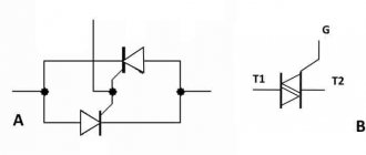
Along with symmetrical dinistors, there are also symmetrical trinistors (triacs, triacs). They are two thyristors with common control, connected back-to-back and placed in one housing. If necessary, the triac can be replaced with two separate devices by connecting them according to the appropriate circuit.
The current-voltage characteristic of the triac is also symmetrical about zero.
Optothyristors
There are devices similar in structure and principle of operation to conventional thyristors, but which are unlocked by light incident on the open thyristor structure. If you combine such a switch and an LED controlled by an external signal source in one housing, you get a device called an optothyristor (thyristor optocoupler).
Specific methods of thyristor control
- Amplitude.
It represents the supply of a positive voltage of varying magnitude to the Ue. The opening of the thyristor occurs when the voltage value is sufficient to break through the control transition of the rectifying current (Irect). By changing the voltage on the UE, it becomes possible to change the opening time of the thyristor.
The main disadvantage of this method is the strong influence of the temperature factor. In addition, each type of thyristor will require a different type of resistor. This point does not add ease of use. In addition, the opening time of the thyristor can be adjusted only while the first 1/2 of the positive half-cycle of the network lasts.
- Phase.
It consists of changing the phase Ucontrol (in relation to the voltage at the anode). In this case, a phase shift bridge is used. The main disadvantage is the low slope of Ucontrol, so it is possible to stabilize the opening moment of the thyristor only for a short time.
- Pulse-phase.
Designed to overcome the shortcomings of the phase method. For this purpose, a voltage pulse with a steep edge is applied to Ue. This approach is currently the most common.
Connection diagram
The control circuit may look different, but in the simplest case, the thyristor switch switching circuit looks like that shown in Figure 2.
A light bulb L is connected to the anode , and the positive terminal of the power source GB is connected to it using switch K2. The cathode is connected to the negative terminal of the power supply.
After power is supplied by switch K2, battery voltage will be applied to the anode and cathode, but the thyristor remains closed and the light does not light. In order to turn on the lamp, you need to press button K1, the signal through resistance R will be sent to the control electrode, the thyristor switch will change its state to open, and the lamp will light up. Resistance limits the current supplied to the control electrode. Pressing the K1 button again does not have any effect on the state of the circuit.
To close the electronic key, you need to disconnect the circuit from the power source using switch K2. This type of electronic component will shut down if the supply voltage at the anode drops to a certain value, which depends on its characteristics. This is how you can describe how a thyristor for dummies works.

