In equipment designs created on the basis of high technology, various automatic processes are constantly being developed and improved. Among them, a servo drive is widely used, installed with the aim of performing constant dynamic movements by individual elements and parts. These devices provide constant control over the angles of rotation of the shaft and set the desired speed in electromechanical devices.
An integral part of these systems are servomotors, which make it possible to control speeds in the desired range within a set period of time. Thus, all processes and movements can be repeated periodically, and the frequency of these repetitions is built into the control system.
Servo for Arduino
A servo drive is a type of drive that can precisely control motion parameters. In other words, it is a motor that can rotate its shaft through a specific angle or maintain continuous rotation at a precise period.
The servo drive's operating circuit is based on the use of feedback (a closed circuit in which the input and output signals are not matched). The servo drive can be any type of mechanical drive, which includes a sensor and a control unit that automatically maintains all the parameters set on the sensor. The servo drive consists of a motor, a position sensor and a control system. The main task of such devices is implementation in the field of servomechanisms. Also, servo drives are often used in such areas as material processing, production of transport equipment, wood processing, metal sheet production, construction materials production and others.
In Arduino robotics projects, servo is often used for simple mechanical actions:
- Rotate the rangefinder or other sensors to a certain angle to measure distance in a narrow field of view of the robot.
- Take a small step with your foot, move your limb or head.
- To create robotic manipulators.
- To implement the steering mechanism.
- Open or close a door, flap or other object.
Of course, the scope of application of servo in real projects is much wider, but the examples given are the most popular schemes.
Application area
At the moment, servos have become quite widespread. They can be found in precision instruments, machines that produce various circuit boards, programmable machines, industrial robots and other mechanisms. Drives of this type have gained great popularity in the aircraft modeling industry due to their efficient energy consumption and uniform movement.
Servo drives change and evolve. At the very beginning of their appearance, they had commutator motors with windings on the rotor. Gradually, the number of windings increased, and the speed of rotation and acceleration also increased. Later, the windings began to be located outside the magnet, which also contributed to increased operating efficiency. Further improvements made it possible to abandon the collector and began to use permanent rotor magnets. The most popular now are servos that operate from a programmable controller. This makes it possible to create high-precision instruments and modern technology.
The ability to achieve high precision is often the deciding factor for servo drive applications. In addition, thanks to new digital developments that allow for various ways to communicate with objects, the system uses a computer for control and configuration, which greatly simplifies operation.
Servo motors are also used in various fields. They can move the output shaft to a predetermined position and hold it automatically. They will also help to give movement to any mechanism coordinated by shaft rotations. For a motor, important parameters are the uniformity and tone of movement, the efficiency of energy expended.
Scheme and types of servos
The operating principle of a servo drive is based on feedback from one or more system signals. The output indicator is fed to the input, where its value is compared with the setting action and the necessary actions are performed - for example, the engine is turned off. The simplest implementation option is a variable resistor, which is controlled by the shaft - when the parameters of the resistor change, the parameters of the current supplying the motor change.
In real servos, the control mechanism is much more complex and uses built-in controller chips. Depending on the type of feedback mechanism used, analog and digital servos are distinguished. The former use something similar to a potentiometer, the latter use controllers.
The entire servo control circuit is located inside the housing, control signals and power are supplied, as a rule, through three wires: ground, supply voltage and control signal.
Continuous rotation servo 360, 180 and 270 degrees
There are two main types of servomotors - with continuous rotation and with a fixed angle (most often, 180 or 270 degrees). The difference between servo limited rotation lies in the mechanical elements of the design that can block the movement of the shaft outside the angles specified by the parameters. Having reached an angle of 180, the shaft will affect the limiter, and it will give a command to turn off the motor. Continuous rotation servomotors do not have such limiters.
Servo gear materials
For most servos, the connecting link between the shaft and external elements is a gear, so it is very important what material it is made of. There are two most affordable options: metal or plastic gears. In more expensive models you can find elements made of carbon fiber and even titanium.
Plastic options are naturally cheaper, easier to manufacture, and are often used in inexpensive servos. For educational projects where the servo makes a few movements, this is not a big deal. But in serious projects, the use of plastic is impossible, due to the very rapid wear of such gears under load.
Metal gears are more reliable, but this, of course, affects both the price and the weight of the model. Thrifty manufacturers can make some parts plastic and some metal, this should also be kept in mind. And, naturally, in the cheapest models, even the presence of a metal gear is not a guarantee of quality.
Titanium or carbon gears are the most preferable option if you are not limited by budget. Lightweight and reliable, such servos are widely used to create models of cars, drones and aircraft.
Advantages of servo motors
The widespread use of servo drives is due to the fact that they have stable operation, high resistance to interference, small size and a wide range of speed control. Important features of servos are the ability to increase power and provide information feedback. And it follows that in the forward direction the circuit is a transmitter of energy, and in the reverse direction it is a transmitter of information that is used to improve control accuracy.
Differences between a servo and a conventional motor
By turning a conventional electric motor on or off, we can generate a rotating motion and cause wheels or other objects attached to the shaft to move. This movement will be continuous, but in order to understand at what angle the shaft has turned or how many revolutions it has made, you will need to install additional external elements: encoders. The servo drive already contains everything necessary to obtain information about the current rotation parameters and can turn off independently when the shaft rotates to the required angle.
Differences between servo and stepper motor
An important difference between a servo motor and a stepper motor is the ability to work with high accelerations and under variable loads. Also, servo motors have higher power. Stepper motors do not have feedback, so the effect of loss of steps may be observed; in servomotors, loss of steps is excluded - all violations will be recorded and corrected. With all these obvious advantages, servomotors are more expensive devices than stepper motors, have a more complex connection and control system and require more qualified maintenance. It is important to note that stepper motors and servos are not direct competitors - each of these devices has its own specific area of application.
Recovery process
Regeneration occurs when the direction (sign) of the load torque changes in relation to the torque of the servomotor. If the recovery energy is small, it accumulates on the DC link capacitors, increasing the voltage across them.
If the difference between the absolute torque values of the load and the servomotor is significant, the voltage on the DC bus capacitors may exceed the threshold level. In this case, the regenerative energy is dumped into the braking resistor.
Other useful materials:
Choosing the optimal motor size Servo drive or stepper motor? PLC Programming Principles
Where to buy popular servos SG90, MG995, MG996
| The most affordable servo option SG90 1.6KG | Servo drives SG90 and MG90S for Arduino at a price below 70 rubles |
| Another option for the SG90 Pro 9g servo from a trusted supplier on Ali | Servo SG90 from reliable supplier RobotDyn |
| Servo tester | Several options for servo testers |
| Protected servo drive with a torque of 15 kg | Servo JX DC5821LV 21KG Full waterproof Core mental gear 1/8 1/10 RC car Scaler Buggy Crawler TRAXXAS RC4WD TRX-4 SCX10 D90 |
| Servo MG996R MG996 Servo Metal Gear for Futaba JR | Servo 13KG 15KG Servos Digital MG995 MG996 MG996R Servo Metal Gear |
Servo control
The decisive factor in controlling servo drives is the control signal, which consists of pulses of constant frequency and variable width.
Pulse length is one of the most important parameters that determines the position of the servo. This length can be set in the program manually using the corner selection method or using library commands. For each brand of device, the length may be different. When the signal enters the control circuit, the generator delivers its pulse, the duration of which is determined using a potentiometer. In another part of the circuit, the duration of the applied signal and the signal from the generator are compared. If these signals are different in duration, the electric motor is turned on, the direction of rotation of which is determined by which of the pulses is shorter. When the pulse lengths are equal, the motor stops.
The standard frequency at which pulses are given is 50 Hz, that is, 1 pulse every 20 milliseconds. At these values, the duration is 1520 microseconds, and the servo is in the middle position. Changing the pulse length leads to rotation of the servo drive - when the duration increases, the rotation is clockwise, and when it decreases, it is rotated counterclockwise. There are duration limits - in Arduino in the Servo library, for 0° the pulse value is set to 544 μs (lower limit), for 180° - 2400 μs (upper limit).
(Image used from amperka.ru)
It is important to consider that on a specific device, the settings may differ slightly from the generally accepted values. For some devices, the average pulse position and width may be 760 µs. All accepted values may also vary slightly due to errors that may occur during the production of the device.
The drive control method is often mistakenly called PWM/PWM, but this is not entirely correct. Control directly depends on the pulse length; the frequency of their occurrence is not so important. Correct operation will be ensured at both 40 Hz and 60 Hz; only a strong decrease or increase in frequency will contribute. If there is a sharp decline, the servo drive will begin to operate jerkily; if the frequency is increased above 100 Hz, the device may overheat. Therefore, it is more correct to call it PDM.
Based on the internal interface, analogue and digital servos can be distinguished. There are no external differences - all the differences are only in the internal electronics. The analog servo drive contains a special chip inside, while the digital servo drive contains a microprocessor that receives and analyzes pulses.
When receiving a signal, the analog servo decides whether or not to change the position and, if necessary, supplies a signal with a frequency of 50 Hz to the motor. During the reaction time (20 ms), external influences may occur that change the position of the servo drive, and the device will not have time to react. A digital servo drive uses a processor that supplies and processes signals at a higher frequency - from 200 Hz, so it can respond faster to external influences and quickly develop the desired speed and torque. Therefore, the digital servo will be better able to hold the set position. At the same time, digital servo drives require more electricity to operate, which increases their cost. The complexity of their production also makes a big contribution to the price. High cost is the only drawback of digital servos; technically, they are much better than analog devices.
Basic provisions of the device
If the duration of the reference and control pulses coincides, the so-called zero torque occurs. At this time, the servo drive motor does not work, the drive shaft is in its original (stationary) position.
As the duration of the control pulse increases, the board records the difference in the indicators, the motor receives voltage and starts moving. In turn, the gearbox begins to influence the output shaft, which rotates in such a way as to achieve an increase in the duration of the reference pulse. As soon as it becomes equal to the control pulse, the engine will stop working.
When the duration of the control pulse decreases, the same thing happens, only exactly the opposite, since the engine begins to rotate in the opposite direction. As soon as the pulses are equal, the engine stops.
Connecting a servo motor to Arduino
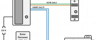
The servo drive has three contacts, which are painted in different colors. The brown wire leads to ground, the red wire leads to the +5V power supply, and the orange or yellow wire leads to the signal wire. The device is connected to the Arduino via a breadboard in the manner shown in the figure. The orange wire (signal) is connected to the digital pin, the black and red wires are connected to ground and power, respectively. To control the servomotor, you do not need to connect specifically to shim pins - we have already described the principle of servo control earlier.
It is not recommended to connect powerful servos directly to the board, because... they create a current for the Arduino power circuit that is not compatible with life - you’ll be lucky if the protection works. Most often, the symptoms of overload and improper power supply of the servo are the “jerking” of the servo, an unpleasant sound and the board rebooting. For power supply, it is better to use external sources, be sure to combine the grounds of the two circuits.
Sketch for controlling a servo in Arduino
Controlling a servo directly by changing the pulse duration in the sketch is a rather non-trivial task, but fortunately we have an excellent Servo library built into the Arduino development environment. We will consider all the nuances of programming and working with servos in a separate article. Here we give a simple example of using Servo.
The operating algorithm is simple:
- First we connect Servo.h
- Create an object of the Servo class
- In the setup block we indicate which pin the servo is connected to
- We use the object's methods in the usual C++ way. The most popular is the write method, to which we supply an integer value in degrees (for a 360 servo these values will be interpreted differently).
An example of a simple sketch for working with a servo drive
An example of a project in which we immediately first set the servo motor to zero angle and then rotate it 90 degrees.
#include Servo servo; // Create an object void setup() { servo.attach(9); // Indicate to the Servo class object that the servo is attached to pin 9 servo1.write(0); // Set the initial position } void loop() { servo.write(90); // Rotate the servo 90 degrees delay(1000); servo.write(1800); delay(100); servo.write(90); delay(1000); servo.write(0); delay(1000); }
Sketch for two servos
And in this example we work with two servos at once:
#include Servo servo1; // First servo drive Servo servo2; // Second servo void setup() { servo1.attach(9); // Indicate to the Servo class object that the servo is attached to pin 9 servo2.attach(10); // And this servo is connected to pin 10 } void loop() { // Set the positions servo1.write(0); servo2.write(180); delay(20); // Change positions servo2.write(0); servo1.write(180); }
Servo control using potentiometer
In this example, we rotate the servo depending on the value received from the potentiometer. We read the value and convert it to an angle using the map function:
//Fragment of a standard example of using the Servo library void loop() { val = analogRead(A0); // Read the value from the pin to which the potentiometer is connected val = map(val, 0, 1023, 0, 180); // Convert a number in the range from 0 to 1023 into a new range - from 0 to 180. servo.write(val); delay(15); }
Servo drive SG90
Characteristics and connection of SG-90
If you are going to buy the cheapest and simplest servo drive, then the SG 90 will be the best option. This servo is most often used to control small, lightweight mechanisms with a rotation angle from 0° to 180°.
SG90 Specifications:
- Command execution speed 0.12s/60 degrees;
- Power 4.8V;
- Operating temperatures from -30C to 60C;
- Dimensions 3.2 x 1.2 x 3 cm;
- Weight 9 g.
Description SG90
Wire colors are standard. The servo drive is inexpensive and does not provide precise settings for the start and end positions. In order to avoid unnecessary overloads and the characteristic crackling sound in the 0 and 180 degree position, it is better to set the extreme points at 10° and 170°. When operating the device, it is important to monitor the supply voltage. If this indicator is greatly overestimated, the mechanical elements of the gear mechanisms may be damaged.
Servo drives MG995 and MG996 tower pro
The MG995 servo is the second most popular servo model most often connected to Arduino projects. These are relatively inexpensive servo motors with much better performance than the SG90.
Specifications MG995
The output shaft on the MG995 rotates 120 degrees (60 in each direction), although many sellers indicate 180 degrees. The device is housed in a plastic case.
- Weight 55 g;
- Torque 8.5 kg x cm;
- Speed 0.2s/60 degrees (at 4.8V);
- Working power 4.8 – 7.2V;
- Operating temperatures – from 0C to -55C.
Description MG995
The connection to the Arduino also occurs via three wires. In principle, for amateur projects it is possible to connect the MG995 directly to the Arduino, but the motor current will always create a dangerous load on the board inputs, so it is still recommended to power the servo separately, not forgetting to connect the ground of both power circuits. Another option that makes life easier would be to use ready-made servo controllers and shields, which we will review in a separate article.
MG996R is similar to MG995 in its characteristics, only it comes in a metal case.
Torque.
One of two main characteristics. Torque (force on the shaft) is a factor responsible for the measure of rotational force applied to the physical body (how much weight the drive can hold in a horizontal position on a lever with a given length parameter). Torque can be nominal (the servo drive can operate with such a torque applied to the shaft for any amount of time) and peak (short-term increased, which is achieved by additionally pumping current into the motor windings). When operating with a torque exceeding the rated one, the motor and driver keys heat up, and prolonged operation (more than a few seconds) can damage the drive. It is by the moment that they look at whether the servo drive is suitable for the task being performed, whether it can rotate what it is supposed to rotate. Different servos produce torque differently; it can be approximately constant over the entire range of revolutions, or drop at low speeds, or vice versa, at high speeds. Torque is provided by the current in the windings, and most servos can briefly supply a torque to the shaft greater than the nominal one specified in the data sheet, but very briefly, so as not to overheat the stator windings.
Converting a servo drive into a continuous rotation servo
As described above, the servo is controlled by variable width pulses that set the angle of rotation. The current position is read from the potentiometer. If you disconnect the shaft and the potentiometer, the servomotor will take the position of the potentiometer slide as at the midpoint. All these actions will lead to feedback being removed. This allows you to control the speed and direction of rotation via the signal wire, and create a continuous rotation servo. It is important to note that a constant rotation servo cannot rotate through a certain angle and make a strictly specified number of revolutions.
To perform the above steps, you will have to disassemble the device and make changes to the design.
In Arduino IDE you need to create a small sketch that will put the rocker in the middle position.
#include Servo myservo; void setup(){ myservo.attach(9); myservo.write(90); } void loop(){ }
After this, the device needs to be connected to Arduino. When connected, the servo will begin to rotate. It is necessary to achieve its complete stop by adjusting the resistor. After the rotation stops, you need to find the shaft, pull out the flexible element from it and install it back.
This method has several disadvantages - setting the resistor to a complete stop is unstable; with the slightest shock/heating/cooling, the adjusted zero point may be lost. Therefore, it is better to use the method of replacing the potentiometer with a trimmer. To do this, you need to remove the potentiometer and replace it with a trimmer resistor with the same resistance. The zero point must be adjusted using a calibration sketch.
Any method of converting a servo into a continuous rotation servo has its drawbacks. Firstly, it is difficult to adjust the zero point; any movement can throw it off. Secondly, the control range is small - with a small change in the pulse width, the speed can change significantly. You can expand the range programmatically in Arduino.
Rotational speed
The second most important characteristic. Rotation speed is a value indicating at what maximum angular speed the drive can rotate; an important value if the motor is used as a drive for mechanical spindles. The speed developed by the servo drive is limited by a number of factors - its type, installed encoder, and rotor balancing.