Last updated January 2, 2022
Today there is an increase in user interest in the implementation in houses and apartments, if not of full-fledged smart home systems, then of some elements of Home Automation (home automation).
In this regard, manufacturers are developing and increasing the production of systems of varying complexity - from full-fledged boxed solutions using AI, to kits based on microcontrollers that allow you to quickly solve application problems of varying complexity.
What is Arduino
Arduino is a platform for adding and programming electronic devices, with control types: manual, semi-automatic and automatic. The platform is a kind of constructor, with prescribed rules for the interaction of elements with each other. The system is open, so every interested manufacturer contributes to the development of Arduino.
Functions of a standard smart home:
- collecting information using sensors;
- data analysis and decision making using a programmable microcontroller;
- implementation of decisions made using commands sent to various devices connected to the system.
The good thing about the Arduino designer is that you can use any smart home elements from different manufacturers in its system. This opportunity allows the platform not to be limited to just one smart home ecosystem, but to select any electronic components to implement solutions to its own problems.
In addition to the huge list of devices connected to the system, the C++ programming environment gives it flexibility. The user can independently program the reaction of system components to emerging events or use an already created library.
Helpful information! Arduino is an Italian company that produces and develops software components for real and simple Smart Home systems, which are aimed at any person interested in this issue. The architecture is completely open, so third-party developers (mainly from China) have already managed to completely copy and release their own alternative elements of the system, and software for them.
You can learn to interact with Arduino in two ways: by independent trial and error, or by using a book with a complete set for a smart home, which will tell you about all the intricacies of working in this system.
Arduino smart home kit
Creating a project on Arduino
We will show the process of creating and setting up an Arduino “smart home” using the example of a system that will include the following functions:
- outdoor and indoor temperature monitoring;
- window state tracking (open/closed);
- monitoring weather conditions (clear/rainy);
- generation of a sound signal when a motion sensor is triggered if the alarm function is activated.
We will configure the system in such a way that the data can be viewed using a special application, as well as a web browser, that is, the user can do this from any place where there is Internet access.
Abbreviations used:
- "GND" - grounding.
- "VCC" - power supply.
- "PIR" - motion sensor.
Necessary components for making a smart home system
For the Arduino smart home system you will need the following:
- Arduino microprocessor board;
- Ethernet module ENC28J60;
- two temperature sensors brand DS18B20;
- microphone;
- rain and snow sensor;
- Motion Sensor;
- reed switch;
- relay;
- resistor with a resistance of 4.7 kOhm;
- twisted pair cable;
- Ethernet cable.
All components cost approximately $90.
To produce a system with the functions we need, we will need a set of devices costing about $90
Designing a smart home Arduino
A smart home “for all occasions” does not exist. Therefore, its design begins with defining the tasks, selecting and placing the main Arduino node, and then the remaining elements. At the final stage, the functionality is connected and finalized using programming.
You can create many projects based on Arduino, and then combine them into a single system. Among these:
- Humidity control in the basement.
- Automatic switching on of convectors when the temperature in the house drops below the permissible level in two possible scenarios - in the presence and absence of a person in the room.
- Turning on the street lights at dusk.
- Send messages about changes in each detected state.
As an example, we can consider designing the automation of a one-story house with two rooms and a basement for storing vegetables. The complex includes seven zones: entrance hall, shower room, kitchen, porch, bedroom, dining room, basement.
When drawing up a step-by-step design plan, we consider the following:
- Porch. When the owner approaches the house at night, the lighting will turn on. You should also take into account the opposite - when leaving the house at night, you also need to turn on the lighting.
- Hallway. When motion is detected and at dusk, turn on the lights. In the dark, it is necessary to have a dim light on the light bulb.
- Basement on the street. When the owner approaches, in the dark, the lamp near the basement door should light up. When opening the door, the light inside comes on and turns off when a person leaves the building. When leaving, the lighting on the porch turns on, and as you move away from the basement, it turns off near the door. Humidity control is installed in the basement and when a critical temperature is reached, several fans are turned on to improve air circulation.
- Shower room. It has a boiler installed. If a person is present in the house, the boiler turns on the water heating. The automation turns off when the maximum heating temperature is reached. When you enter the toilet, the hood and light turn on.
- Kitchen. The main lighting is turned on manually. If the owner of the house is absent from the kitchen for a long time, the light turns off automatically. The hood turns on automatically while cooking.
- Dining room. Light control is similar to that in the kitchen. While present in the kitchen, it is possible to give a voice command to the smart speaker assistant so that it starts the music.
- Bedroom. The lighting is turned on manually. But there is an automatic shutdown if there is no person in the room for a long time. Additionally, you need to turn off the lighting when there is a clap.
Convectors are located throughout the house. It is necessary to automatically control the maintained temperature in the house in two modes: when a person is in the house and during his absence. In the first option, the temperature should fall no lower than 20 degrees and rise no higher than 22. In the second, the temperature of the house should fall no lower than 12 degrees.
The project is ready, all that remains is to implement it.
Pros and cons of the system
Before selecting components and modules for creating automation in a smart home, you should pay attention to both the advantages and disadvantages of the system.
Advantages of the Arduino smart home:
- Using components from other manufacturers with the Arduino controller.
- Creation of your own smart home programs, since the source code of the project is open.
- The programming language is simple, there are many manuals for it on the Internet, even a beginner can figure it out.
- A simple project can be done in one hour of practice using default libraries designed for: reading button signals, outputting information to LCD displays or seven-segment indicators, and so on.
- You can power it, send commands and messages, program, or transfer ready-made software solutions to Arduino using a USB cable.
Flaws:
- The Arduino IDE development environment is a program built in Java, which includes: a code editor, a compiler, and transferring firmware to the board. Compared to modern solutions for 2022, this is the worst development environment (in the form in which it is presented). Even when you move to another development environment, you will have to leave the IDE for firmware.
- Small amount of flash memory for creating programs.
- The bootloader needs to be flashed for each microcontroller shield to complete the project. Its size is 2 KB.
- An empty project takes up 466 bytes on the Arduino UNO and 666 bytes in the Mega board's ROM.
- Low processor frequency.
Power supply for Arduino Mega 2560
Arduino Mega can be powered from a USB port or an external source. The power source is selected automatically.
External power (not via USB) can be supplied from a power supply or battery. The power supply connects to a 2.1 mm connector on the board, which has a central positive pin. Battery power can be connected to the GND and VIN pins of the POWER connector.
The board can operate from an external voltage source in the range from 6 to 20 volts. If the power supply voltage is less than 7 V, the 5 V pin may have less than 5 V and the board may become unstable. If the external source voltage exceeds 12 V, the voltage regulator may overheat and damage the board. The recommended supply voltage range is 7-12 volts.
Smart home modules and solutions based on Arduino
The main element of a smart home is the central microcontroller board. Two or more interconnected boards are responsible for the interaction of all elements of the system.
There are three main microcontrollers in the system:
- Arduino UNO is a medium-sized board with its own processor and memory. The basis is the ATmega328 microcontroller. There are 14 digital inputs/outputs (6 of them can be used as PWM outputs), 6 analog inputs, a 16 MHz quartz resonator, a USB port (on some USB-B boards), a connector for in-circuit programming, and a RESET button. Flash memory – 32 KB, random access memory (SRAM) – 2 KB, non-volatile memory (EEPROM) – 1 KB.
Arduino UNO
- Arduino NANO is a board of minimal dimensions with an ATmega328 microcontroller. The difference from UNO is its compactness, due to the type of contact pads used - the so-called “comb of legs”.
Arduino Nano
- Arduino MEGA is a large board with an ATMega 2560 microcontroller. Clock frequency is 16 MHz (as in UNO), there are 54 digital pins instead of 14, and 16 analog pins instead of 6. Flash memory - 256 KB, SRAM - 8 KB, EEPROM - 4 .
Arduino Mega
Arduino UNO is the most common board, as it is easier to work with in terms of installation work. The NANO board is smaller and more compact - this allows it to be placed in any corner of a smart home. MEGA is used for complex tasks.
Now the 3rd generation of Arduino boards (R3) is presented on the market. Typically, when purchasing a board, a StarterKit training kit is included, containing:
- Stepper motor.
- Control manipulator.
- Electrocircuit relay SRD-05VDC-SL-C 5 V.
- Solderless board for MB-102 breadboard.
- Module with access card and two tags.
- Sound sensor LM393.
- Sensor with liquid level measurement.
- Two simple devices for displaying digital information.
- LCD display for displaying multiple characters.
- LED matrix TC15-11GWA.
- Three-color RGB module.
- Temperature sensor and humidity meter DHT11.
- Module real time DS1302.
- Servo drive SG-90.
- IR Remote Control.
- Keyboard matrix with 16 buttons.
- 74HC595N shift register chip for additional outputs.
- Basic small electronics components for circuit design.
You can also find a more complete kit for creating a smart home using Arduino from scratch with your own hands. And to implement another project, in addition to the elements of the training kit, you will need additional things and modules.
Sensors and sensors
To monitor the temperature and humidity in your home and basement, you will need a temperature and humidity sensor. In a smart home designer, this is a board that combines temperature and humidity sensors and an LCD display for data output.
The board is complemented by compatible motion sensors or other PIR sensors that determine the presence or absence of a person in the coverage area, and is linked via a relay to the lighting.
Arduino sensor
The gas sensor will allow you to quickly respond to smoke, carbon dioxide or gas leaks, and when connected to the circuit, will automatically turn on the hood.
Arduino Gas Sensor
Relay
The Relay circuit component connects electrical circuits with different parameters to each other. A relay turns external devices on and off by opening and closing the electrical circuit in which they are located. With the help of this module, lighting control occurs in the same way as if a person stood and independently switched the toggle switch.
Arduino relay
LEDs can indicate the state in which the relay is at a given time. For example, red means the lighting is off, green means the lighting is on. The connection diagram to the lamp looks like this.
For a larger project, it is better to use a relay bus, such as an eight-channel 5V relay module.
Controller
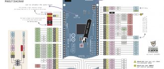
The controller is an Arduino UNO board. For installation you need to know:
- description of elements;
- board pinout;
- schematic diagram of the board's operation;
- ATMega 328 microcontroller pinout.
Software setup
Programming of connected Arduino elements takes place in the IDE editor. You can download it from the official website. For programming, you can use ready-made libraries.
Or use a ready-made sketch solution Ardublock - a graphical programming language built into the IDE. Essentially, all you need to do is download and install the software, then use the blocks to create your diagram.
Arduino Mega 2560 CH340G
This board has all the properties of the classic Arduino Mega 2560 Rev3 board. The main differences from the original are due to the fact that to reduce the cost of the board, a USB bridge is used, made on a budget CH340G chip. All elements of external connections, including port names, on this board fully correspond to the circuit diagram of the original board.
For the CH340G USB bridge chip, you need to install drivers on your computer, which can be downloaded here.
Schematic diagram
Remote control of a smart home
To connect the board to the Internet, you will need:
- Wi-Fi adapter configured to receive and transmit signals through the router;
- or a Wi-Fi router connected via an Ethernet cable.
There is also a Bluetooth remote control option. Accordingly, a Bluetooth module must be connected to the board.
There are several options for controlling an Arduino smart home: using a smartphone application or via the web. Let's look at each in more detail.
Management Applications
Since this design system is not a closed ecosystem, there are a lot of applications implemented for it. They differ from each other not only in the interface, but also in the performance of various tasks.
Blynk
The application for Android and iOS with an excellent design allows you to develop projects that have direct access to the event trigger on the Arduino board. But for the application to work, you need an Internet connection, otherwise it is not possible to interact with it.
Virtuino
A cool free application for Android that allows you to combine projects into one and control several boards at once using Wi-Fi or Bluetooth.
Allows you to create visual interfaces for LEDs, switches, counters, and analog circuit devices. It contains training materials and a library of knowledge about the process of working with the system.
Bluino Loader – Arduino IDE
The phone application is a software environment for Arduino coding. With its help, you can quickly and easily compile code into a file, and then send it via OTG adapter to the board.
Arduino Bluetooth Control
The application controls Arduino contacts and controls basic functions via Bluetooth. But, the program is not aimed at remote control, only monitoring.
RemoteXY: Arduino Control
Using the application, the user can create his own board management interface. The connection occurs via Wi-Fi, Bluetooth or the Internet via a cloud server.
Bluetooth Controller 8 Lamp
Created using Bluetooth modules HC-05, HC-06 and HC-07, the application provides eight-channel control. In this way, control and regulation of the Arduino operation is achieved, in accordance with each of the 8 LEDs.
BT Voice Control for Arduino
The application is specially designed for remote control of data from an ultrasonic sensor connected via Bluetooth via Arduino. Connections are made via the HC-05 module.
Once connected, the ultrasonic sensor will be able to transmit information about the distance to the object, which will be displayed in the application interface on the phone.
IoT Wi-Fi controller
An application with an interface that informs about the configuration of each input/output on the Arduino board. In the utility you can switch GPIO in real time and show the ADC value.
Web client
You can control the smart home board remotely by placing the receipt and processing of smart home data on a web server. Naturally, you need to create a server for the Arduino smart home yourself.
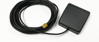
For these purposes, you will need an Arduino Ethernet Shield - a network extension for the Arduino Uno pins, which allows you to add an RJ-45 connector for connecting to the network.
When connecting remotely, it is necessary to provide external power to the board other than USB.
Then, connect the board via USB to the computer, and via Ethernet the board to the router, which distributes the Internet to the computer. When the connection is established correctly, you will see a green light on the port.
After that, you need to use the Ethernet shield libraries and write code in the IDE to create a server and send data to the server. An example of a homemade server is well described in this manual.
SMS notifications
Using the plug-in GSM library in the Arduino IDE you can:
- Work with voice calls.
- Receive and send SMS.
- Connect to the Internet via GPRS.
The circuit operates through a special GSM expansion board containing a special modem.
You can learn about creating a universal alarm system on Arduino, with sending SMS notifications to a smartphone, from the corresponding video instructions.
I/O Ports
- Digital inputs/outputs : pins 0–53 Logical level of one - 5 V, zero - 0 V. Maximum output current - 40 mA. Pull-up resistors are connected to the contacts, which are disabled by default, but can be enabled by software.
- PWM : Pins 2-13 and 44-46 Allows 8-bit analog values to be output as a PWM signal.
- ADC : pins A0–A16 16 analog inputs, each of which can represent an analog voltage as a 10-bit number (1024 values). The ADC capacity is 10 bits.
- TWI/I²C : pins 20( SDA ) and 21( SCL ) For communication with peripherals via a synchronous protocol, via 2 wires. To work, use the Wire library.
- SPI : pins 50( MISO ), 51( MOSI ), 52( SCK ) and 53( SS ). SPI interface commutation pins (use the SPI library).
- UART:
- Serial : pins 0(RX) and 1(TX);
- Serial2 : pins 17(RX) and 16(TX);
- Serial3 : pins 15(RX) and 14(TX).
Serial1 : pins 19(RX) and 18(TX);
These pins are used to receive (RX) and transmit (TX) data over the serial interface. Pins 0(RX) and 1(TX) are connected to the corresponding pins of the ATmega16U2 chip, which acts as a USB-UART converter.
Learning the basics of Arduino
Using the Arduino 2 Handbook application, you can master the material within two weeks. The application is completely offline and does not require an Internet connection. It describes the following information: functions, data, operators, Arduino libraries.
After mastering the basics, you can visit the Habrahabr resource, which contains 100 lessons on programming on Arduino.
For those who are accustomed to drawing knowledge from books, “Jeremy Bloom: Learning Arduino” will be a wonderful guide for theory and practice.
The most popular Arduino tutorial
The book provides basic information about Arduino hardware and software. The principles of programming in the Arduino IDE are described. The author of the book teaches the analysis of electrical circuits and reading technical specifications. The information from the book will help you decide in the future on the choice of suitable parts for creating a smart home.
The author gives examples of the operation of electric motors, sensors, indicators, servos, and various data transfer interfaces. The book contains illustrated components, wiring diagrams and program listings. Most importantly, the components for practice that the author works with are not expensive, not complicated and popular material for experimental assemblies at home.
Description of Arduino Mega 2560 pins
Mega board digital pins
Pins numbered 0 to 53 are digital. This means that you can only read and apply two types of signals to them: HIGH and LOW. With PWM you can also use digital ports to control the power of connected devices.
| Pin | Addressing | Special appointment | PWM |
| 0 | 0 | RX (Serial) | |
| 1 | 1 | TX (Serial) | |
| 2 | 2 | Interrupt input 0 | PWM |
| 3 | 3 | Interrupt input 1 | PWM |
| 4 | 4 | PWM | |
| 5 | 5 | PWM | |
| 6 | 6 | PWM | |
| 7 | 7 | PWM | |
| 8 | 8 | PWM | |
| 9 | 9 | PWM | |
| 10 | 10 | PWM | |
| 11 | 11 | PWM | |
| 12 | 12 | PWM | |
| 13 | 13 | Built-in LED | PWM |
| 14 | 14 | TX (Serial3) | |
| 15 | 15 | RX (Serial3) | |
| 16 | 16 | TX (Serial2) | |
| 17 | 17 | RX (Serial2) | |
| 18 | 18 | TX (Serial1) Interrupt input 5 | |
| 19 | 19 | RX(Serial1) Interrupt input 4 | |
| 20 | 20 | I2C SDA Interrupt Input 3 | |
| 21 | 21 | I2C SCL Interrupt Input 2 | |
| 22-43 | 22-43 | ||
| 44 | 44 | PWM | |
| 45 | 45 | PWM | |
| 46 | 46 | PWM | |
| 47 | 47 | ||
| 48 | 48 | ||
| 49 | 49 | ||
| 50 | 50 | MISO | |
| 51 | 51 | MOSI | |
| 52 | 52 | SCK | |
| 53 | 53 | SCL |
Analog board pins
The Mega2560 platform has 16 analog inputs, each with a resolution of 10 bits (i.e., can take 1024 different values). The standard pins have a measurement range of up to 5 V relative to ground, however it is possible to change the upper limit using the AREF pin and the analogReference() function.
| Pin | Addressing | Special appointment |
| A0 | A0 or 54 | |
| A1 | A1 or 55 | |
| A2 | A2 or 56 | |
| A3 | A3 or 57 | |
| A4 | A4 or 58 | TCK |
| A5 | A5 or 59 | TMS |
| A6 | A6 or 60 | TDO |
| A7 | A7 or 61 | TDI |
| A8 | A8 or 62 | PCINT16 |
| A9 | A9 or 63 | PCINT17 |
| A10 | A10 or 64 | PCINT18 |
| A11 | A11 or 65 | PCINT19 |
| A12 | A12 or 66 | PCINT20 |
| A13 | A13 or 67 | PCINT21 |
| A14 | A14 or 68 | PCINT22 |
| A15 | A15 or 69 | PCINT23 |
Additional pins on the board
- AREF — Reference voltage for analog inputs. Used with the analogReference() function.
- Reset - A low signal on the pin resets the microcontroller. Typically used to connect a reset button on an expansion board, which blocks access to the button on the Arduino board itself.
Power pins
- Vin : Input voltage of the Arduino board when using an external source (if there is no 5 volts from the USB connection or other power source). You can supply power to this pin, or, if power is supplied to the 2.1 mm jack, then you can get the supply input voltage from this pin.
- 5V : The voltage on these pins is regulated by the voltage regulator built into the board. The board can be powered either via the 2.1mm power jack (7-12V), via the USB connection (5V), or via the VIN pin (7-12V) on the board. Supplying power through the 5V or 3.3V pins bypasses the regulator and can damage the board. This is not recommended.
- 3.3V : The 3.3 volt voltage is generated using the regulator built into the board. The maximum current consumption should not exceed 50 mA.
- GND : Ground terminals.
- IOREF : This pin provides the reference voltage with which the microcontroller operates. To properly configure external boards, you can read the voltage from this pin and select the appropriate power supply or enable voltage converters to operate with 5 V or 3.3 V.
Water your garden and greenhouse with Arduino
If you have a garden that you need to water regularly—perhaps you love flowers, or you have a greenhouse filled with tomatoes and cucumbers that you're looking forward to—staying on top of watering your garden or greenhouse can be challenging if you're traveling or going out in the evening (you should avoid watering anything during the day as this can act as a lens for the sun to burn the leaves).
The solution is automation, and the Arduino key, called Garduino in this video, is the key.
Using specialized soil moisture and temperature sensors, Arduino can determine when plants need watering and dose the water. Great!
GUI for control from a computer
#! /usr/bin/python3 # coding: utf-8 import time import serial import os from tkinter import * from tkinter import ttk from tkinter.ttk import Combobox import glob class Box_create(): def __init__(self, text_lable, list_add, col, row): self.text_lable = text_lable self.list_add = list_add self.col = col self.row = row lbl = Label(window, text=self.text_lable) lbl.grid(column=self.col - 1, row=self .row) self.combo = Combobox(window) self.combo['values'] = (self.list_add) self.combo.current(0) self.combo.grid(column=self.col, row=self.row ) @property def print_get(self): return self.combo.get() class Button_create(): def __init__(self, text_lable, command, col, row): self.text_lable = text_lable self.command = command self.col = col self.row = row self.button = Button(window) self.button['text'] = (self.text_lable) self.button['command'] = (self.command) self.button.grid(column= self.col, row=self.row) @property def print_get(self): print(self.button.get()) return self.button.get() ###class lable start class Lable_create(): def __init__( self, text_lable, col, row): self.text_lable = text_lable self.col = col self.row = row self.lable = Label(window) self.lable['text'] = (self.text_lable) self.lable. grid(column=self.col, row=self.row) def label_text_configure(self, text_lable): self.text_lable = text_lable self.lable['text'] = (self.text_lable) @property def print_get(self): print (self.lable.get()) return self.lable.get() def port_search(): ports = [] if sys.platform.startswith('win'): ports = ['COM%s' % (i + 1) for i in range(25)] elif sys.platform.startswith('linux'): ports = glob.glob('/dev/tty[A-Za-z]*') else: raise EnvironmentError('Unsupported platform') return ports def serial_port_select(): global serial_port_name global serial_port_speed serial_port_name = port_search_box.print_get serial_port_speed = 9600 port_select_label.label_text_configure(serial_port_name) os.system('sudo chmod 0666 ' + serial_port_name) send_data_to_arduino() def send_data_to_arduino(symb= 0) : out_label.label_text_configure('FAIL') # symb = str(re.sub(r'[\(\)\[\]\ ,\.rbn_dictvalues;:\'\\]', "", str(set_mode. values()))) symb = str(set_mode['onoff']) + str(set_mode['mode']) + str(set_mode['amode']) + str(set_mode['temp']) ser = serial .Serial(serial_port_name, serial_port_speed, timeout=5) print(serial_port_name, serial_port_speed) print('Sent:', symb) symb1=':' ser.write(symb.encode()) for i in range(5000): window .update() if str(symb1) in str(ser.readline()): out_label.label_text_configure('OK') print('Received:', str(ser.readline())) resive_data_from_arduino() break else: out_label .label_text_configure('undefined') def resive_data_from_arduino(): #data: #:001366; ser = serial.Serial(serial_port_name, serial_port_speed, timeout=5) print(serial_port_name, serial_port_speed) symb = str(':') for i in range(50): window.update() if symb in str(ser.readline( )): out_label.label_text_configure('OK') print('Received:', ser.readline()) read_data = re.sub(r'[rbn;:\'\\]', "", str(ser. readline())) #set_mode_label.label_text_configure(time.strftime("%Y/%m/%d-%H:%M:%S") + ' — ' + read_data) read_serial_data_list.append(read_data) read_data_to_file(read_data ) # read_serial_data_list_label.label_text_configure(read_serial_data_list[-1]) read_serial_data_list_label.label_text_configure('On/Off: ' + str(read_serial_data_list[-1])[0] + ';\nAutomatic mode: ' + str(read_serial_data_list[-1] )[1] + ';\nHeating mode: ' + str(read_serial_data_list[-1])[2] + ';\nCube shutdown temperature: ' + str(read_serial_data_list[-1])[3:5] + ' ,' + str(read_serial_data_list[-1])[5]) read_serial_temp_label.label_text_configure('Temperature in the cube: ' + str(read_serial_data_list[-1])[6:8] + ',' + str(read_serial_data_list[-1 ])[8:10] + ';\nPace to steam: ' + str(read_serial_data_list[-1])[10:12] + ',' + str(read_serial_data_list[-1])[12:14] + ' ;\nPace after steam: ' + str(read_serial_data_list[-1])[14:16] + ',' + str(read_serial_data_list[-1])[16] + str(read_serial_data_list[-1])[17]) break else: out_label.label_text_configure('Receiving data') def read_data_to_file(data_string): read_data_file = open('data_string.txt', 'a') read_data_file.write('\n' + time.strftime("%Y_%m_ %d_%H_%M_%S", time.localtime()) + ':' + data_string) read_data_file.close() def run_select_0(): global run run = '0' run_label.label_text_configure(run) window.update( ) def run_select_1(): global run run = '1' run_label.label_text_configure(run) window.update() def at_func_run(): global run if run == '1': global flag_run if flag_run == 0: flag_run = 1 global time_to_run global start start = time.time() else: if time.time() > start + time_to_run: resive_data_from_arduino() flag_run = 0 from_func_run_label.label_text_configure(run) window.update() else: pass window.update() else : from_func_run_label.label_text_configure(run) window.update() window.update() def run_function_sleep(): pass def add_onoff_to_list(): set_mode.update({'onoff': onoff_select_box.print_get}) set_mode_label.label_text_configure(set_mode) def add_mode_to_list (): set_mode.update({'mode': mode_select_box.print_get}) set_mode_label.label_text_configure(set_mode) def add_amode_to_list(): set_mode.update({'amode': amode_select_box.print_get}) set_mode_label.label_text_configure(set_mode) def add_temp_to_list (): set_mode.update({'temp': temp_select_box.print_get}) set_mode_label.label_text_configure(set_mode) #all kinds of crap global serial_port_name serial_port_name = " read_serial_data_list = [] #in resive_data_from_arduino() append set_mode = {'onoff': 1 , 'mode': 2, 'amode': 0, 'temp': 987} onoff = [0, 1] mode = [0, 1, 2] temp = [] temp_select = [] run = 0 # refers to startup by function time flag_run = 0 # refers to the start time of the function start = 0 # in this variable we set the start time time_to_run = 3 # run once every N seconds for i in range(970, 999): # here we create a list for selecting the final temperature in the box temp.append(i) temp_select.append(i/10) amode_list = [] for i in range(9): amode_list.append(i) print(temp) window = Tk() window.title(“DISTSYS. RU") window.geometry("850×600") port_select_label = Lable_create('/serial/port/select', 1, 2) out_label = Lable_create('output test', 2, 2) set_mode_label = Lable_create(set_mode, 3 , 2) port_search_box = Box_create('Serial port', port_search(), 1, 3) port_search_btn = Button_create('Connect', serial_port_select, 2, 3) onoff_select_box = Box_create('On/Off', onoff, 1, 4) onoff_select_btn = Button_create('Save', add_onoff_to_list, 2, 4) mode_select_box = Box_create('Mode', mode, 1, 5) mode_select_btn = Button_create('Save', add_mode_to_list, 2, 5) amode_select_box = Box_create('Heating', amode_list, 1, 6) amode_select_btn = Button_create('Save', add_amode_to_list, 2, 6) temp_select_box = Box_create('Final temperature', temp_select, 1, 7) temp_select_btn = Button_create('Save', add_temp_to_list, 2, 7) temp_resive_data_btn = Button_create('Receive data', resive_data_from_arduino, 2, temp_resive_data_btn = Button_create('Send data', send_data_to_arduino, 3, read_serial_data_list_label = Lable_create('READ SERIAL DATA LIST', 1, 10) read_serial_temp_label = Label_create('READ SERIAL DATA LIST TEMPs', 1, 11) run_label = Lable_create(run, 2, 12) from_func_run_label = Lable_create(run, 3, 12) run_label_info = Lable_create('Receiving data', 1, 13) run_select_btn1 = Button_create('enable', run_select_1, 2, 13) run_select_btn2 = Button_create('turn off', run_select_0, 3, 13) n=0 while n == 0: at_func_run() window.mainloop()
Automation
Do you need automation for a moonshine still?
- Votes: (0%)
- Votes: (0%)
- Votes: (0%)
| Total votes: |
| First voice: |
| Last voice: |
This article is not about automation, but about heating element control. Development of the topic in the article: new automation (version 2).
I thought that this would be the simplest thing, but time has shown the opposite)))... Although it’s probably even the other way around, I complicated everything and in practice it turned out that we need to take it more simply. Since this is not a ratification column, but simply a distiller, there is no need to maintain a constant temperature by controlling the heating element by milliseconds. By turning on the heating element for seconds, you can achieve a constant, but uneven (which in our case is not important) flow of steam from the distillation cube. / Subsequently, when the heating element is controlled for about 200-700 milliseconds on/off, the stream of steam in the steam chamber shows that the process is proceeding evenly, incomparable to control by seconds. The temperature at the inlet to the steam chamber responds quite vividly to changes in the heating mode./
About heating elements - only stainless steel heating elements. It is highly recommended not to use galvanized steel or brass with food-grade coating (the coating will come off after 4-5 distillations). There are also copper heating elements, but I don’t see the point in copper heating elements.
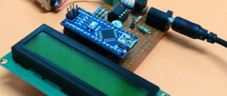
So, I ordered an ARDUINO UNO R3 controller, relays, LEDs, a set of resistances of different ratings, and a DALLAS DS18B20 temperature sensor (in my opinion). Only 2 pieces each so you can quickly replace them. After thinking about how to deliver a temperature sensor to the steam zone in a distillation cube, suddenly a rod from a Parker pen caught my eye, it was ideal for this purpose: thin walls, on one side it is solid (no need to solder, crumple, etc.), suitable in length and diameter. The rod was grabbed, sawed off from the feather side and raped. In order to get rid of ink residues, the rod was soaked in acetone for a week (I just forgot about it))). Then he pulled it out, wiped it, after which it lay there again for a week. Next, the sensor was placed inside the rod and sealed with silicone gaskets. The silicone baking dish really helped out, there was enough for everything without saving and there was still 70% left. Then the rod was “installed”)))… Well, it wasn’t embedded)))… into the body from the exhaust valve through silicone gaskets. Of course, it was possible to order a ready-made thermometer in a sealed case from the Chinese, but somehow I didn’t order it.
Everything was assembled, the program was written, a test stand was assembled from a box and a lamp, the logic was worked out (as it was, based on my then experience and understanding of the process), but again there was a rush, the mash was approaching, and no one canceled a bunch of things, I didn’t bother to find and buy a thermometer to measure real temperature.
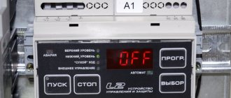
Diagram of the first automation option (in the second option, I removed the block of 5 LEDs and installed a screen from Nokia 5510, purchased on Aliexpress, using the program you can easily figure out what is connected where, the diagram is an example of connecting elements):
After the first distillation, an electronic thermometer was ordered and it was discovered that: 1. The difference in the readings of the thermometer and the sensor is about 2 degrees (I still haven’t decided what to believe), and the inertia of the sensor itself when cooling is quite large, but this is not important. 2. The installed kilowatt heating element, in operating mode 4/6, 4/7 (heating, sec/pause, sec) almost until the end of distillation, maintains a very smooth increase in temperature, 0.3-0.5 degrees for 20-30 minutes, while the process does not stop and it goes on constantly. 3. A problem with the operation of Chinese relays has been identified. Relays from a standard shield are not suitable for a 10A Arduino. It was not clear what was happening, for a while everything worked fine, then the temperature began to rise quickly and the only solution was to turn off the device. It became clear that the relay could not cope with the function assigned to it. The contacts were sticking and at one point the relay contacts were simply welded. The relay was urgently replaced to complete the distillation with a new one, after which the search began for a more reliable option.
It was decided to control the triac using a relay or optocoupler. At first a small triac was installed, later it was lost and I can no longer say or look at the markings, but it got quite hot. After that, I got hold of a monster triac BTA41-800B (40A according to the datasheet) and screwed it to a fairly large radiator. But this connection also heats up when the heating element is running at full power, without a fan it’s kind of scary, put the fan on - no problem.
Scheme:
Verdict: works great, without complaints or surprises. While I turn on the fan for primary heating, I will then automate this process (this will be done in further modifications).
After I stopped thinking that the contacts of the relay might stick and the process would become uncontrollable, further modernization began.
Type of automation:
The principle of modularity seemed tempting to me, but later I realized that it was breaking me to constantly take out several components, arrange them, connect them, and after all all the actions were done in the reverse order, and there were a lot of wires - so in the next version everything is arranged in one case.
Goal: to optimize the process as much as possible and remove control over it (at least face-to-face).
Now the idea of the program (sketch) is this:
- At the beginning of the cycle, we make a request to the temperature sensor, time the circulation time, and after a second we receive the temperature from it. I do this because otherwise problems with buttons will result if delay (1000) is set.
- Next, using buttons, we define variables, which are then processed by conditions.
- and the conditions themselves.
Sketch on this page
Not to judge strictly, I understand that it could have been made more beautiful, functions could have been used... but since I finished it a bunch of times and sometimes wrote on the bus on a tablet, this is how it turned out. Some of the comments are also old and irrelevant - I promise to look into it /not done - I don’t see the point, the new sketch is well commented and more functional/.
At this point, quite a lot of distillations had been carried out and it was experimentally determined that the optimal heating mode for selecting heads (with the same kilowatt heating element, heating, sec/pause, sec) is 4/7 - this is the starting power of distillation after the start of the process. Next, I decided that two runs is the minimum amount. Accordingly, the first distillation can be automated from the end of the selection of heads until the desired temperature, determined by me, is reached. The second distillation, by definition, is fractional, festive and subject to tasting)))… here the automation is superfluous (I thought wrongly, the second distillation can also be automated and stopped when it reaches 45-50%), but it is necessary to manually influence the heating power, not often, but need to. It would also be nice to notify with a sound when the next half liter is filled (or else run and see what happens))) - this can be solved quite simply if there are free pins on the controller. In the future, there are still thoughts on modernization - introducing a web server to control the process from the couch, but that will come later)))
Remaking (modernizing) something is more difficult than doing it anew. The installed LCD screen, 4 buttons, 3 LEDs, beeper, temperature sensor and relay have eaten away all the pins on the controller, leaving only 2 analog ones. All this was not originally intended or planned, so it turned out to be such a plug... Of course, 2 pins are enough to implement control over the filling of the container, but it will not save you from a complete rework, because... I have an idea on how to do all this more compactly and with greater functionality and comfort, again)))
Arduino program:
#include #include #include OneWire ds(10); // D7 - Serial clock out (CLK oder SCLK) // D6 - Serial data out (DIN) // D5 - Data/Command select (DC oder D/C) // D4 - LCD chip select (CE oder CS) / / D3 - LCD reset (RST) Adafruit_PCD8544 display = Adafruit_PCD8544(7, 6, 5, 4, 3); int ReleDevice = 2; //relay is connected to the 2nd pin int LedReleDevice = A2; // LED indicating relay operation int Beeper = 9; // BEEPER PIN int StartShow = 0; // variable for enumerating LEDs at startup int LedPin1 = A0; // LED of button 1 on port A0 int ButPin1 = 8; // Button 1 on pin 8 int LedPin2 = A1; // LED of button 2 on port A1 int ButPin2 = 13; // Button 2 on pin 13 int FlipButMinus = 12; // Rocker minus button int FlipButPlus = 11; // Rocker plus button int flag_B1 = 0; // button state flag 1 (used to track button activation) int flag_B2 = 0; // button 2 state flag (used to track button activation) int flag_FlipButMinus = 0; // state flag “FlipButton minus” (used to track button activation) int flag_FlipButPlus = 0; // state flag “Rocker plus” (used to track button activation) int OnOff = 0; // variable on and off the initial heating mode up to 68 degrees (button 1) int HeadOff = 0; // variable for the end of the head selection mode and the beginning of heating to 78 degrees (button 2) int BasicModeU = 4; // switching mode for step-by-step temperature set (using the rocker) int BasicModeD = 7; // mode for switching step-by-step temperature set (using the rocker) int TempUpSlow = 0; // fast/soft heating mode tracking variable // initial heating/pause ratio unsigned long tD = 7000; // (time down) time the relay is turned off in soft heating mode (msec) unsigned long tU = 4000; // (time up) time the relay is turned on in soft heating mode (msec) unsigned long tDr = 0; unsigned long tUr = 0; // *** unsigned long AllTime; // variable for recording the time elapsed since the start of the program unsigned long MemTime; // variable for recording the start time of the event relative to the time elapsed since the beginning of the program unsigned long AllTempTime; // variable for recording the time elapsed since the start of the program for polling DALLAS DS18 (temperature) unsigned long MemTempTime; // variable for recording the start time of the event relative to the time elapsed since the beginning of the program for polling DALLAS DS18 (temperature) int flagTemp = 0; // tracking variable for temperature sensor polling int tTempTemp = 0; // temporary variable for recording the time calculation from the last sensor poll, not entirely correct, but from the code you can figure out why)))) int Temp = 0; int data[10]; int TempBeepMode_1 = 0; // | variables for the beeper when the relay is turned on/off int TempBeepMode_2 = 0; // | int TempBeepMode_3 = 0; // | int TempBeepMode_4 = 0; // | int TempBeepMode_5 = 0; // | int TempBeepMode_6 = 0; // | int TempBeepMode_7 = 0; // | int Temp1 = 87; int Temp2 = 89; int Temp3 = 91; int TempEnd = 96; unsigned long tD1 = 6000; unsigned long tD2 = 5000; unsigned long tD3 = 4000; void setup() { display.begin(); // initialize the display display.setContrast(60); // set the LCD contrast display.clearDisplay(); // clear the screen pinMode(LedPin1, OUTPUT); pinMode(LedPin2, OUTPUT); pinMode(ReleDevice, OUTPUT); pinMode(Beeper, OUTPUT); pinMode(LedReleDevice, OUTPUT); digitalWrite(ReleDevice, 0); digitalWrite(LedReleDevice, 0); Serial.begin(9600); // analogWrite(9, 20); // value must be between 0 and 255 delay(100); // analogWrite(9, 0); delay(50); // analogWrite(9, 20); // value must be between 0 and 255 delay(100); // analogWrite(9, 0); delay(50); // analogWrite(9, 20); // value must be between 0 and 255 delay(100); // analogWrite(9, 0); delay(50); } void BeepFunction(){ analogWrite(9, 20); // +BEEP value must be between 0 and 255 delay(30); analogWrite(9, 0); // -BEEP } void loop() { // *** START TEMPERATURE if (flagTemp == 0){ byte data[2]; // | if you turned on the main mode (up to 78 degrees) | ds.reset(); // | measure the temperature and unlock the block | ds.write(0xCC); // | 5 LEDs | ds.write(0x44); flagTemp = 1; // set the flag to skip this block until 1000 ms have passed MemTempTime = millis(); // mark the time }else{ AllTempTime = millis(); // tTempTemp = AllTempTime - MemTempTime; if (tTempTemp < 1000){ flagTemp = 1; }else{ flagTemp = 0; ds.reset(); ds.write(0xCC); ds.write(0xBE); data[0] = ds.read(); data[1] = ds.read(); Temp = (data[1]<<8)+data[0]; Temp = Temp>>4; } } // *** END TEMPERATURE // *** START OF BUTTON // button 1 (OnOff) if (digitalRead(ButPin1) == HIGH && flag_B1 == 0) { digitalWrite(LedPin1, !digitalRead(LedPin1)); //change the state of LED1 flag_B1 = 1; //set the flag for pressing the button BeepFunction(); if(OnOff == 0) { // OnOff = 1 is a permanently switched relay OnOff = 1; TempUpSlow = 0; }else if(OnOff == 1){ // OnOff = 2 is a smooth heating mode on/off. (tD; tU) OnOff = 2; TempUpSlow = 0; }else{ OnOff = 0; HeadOff = 0; TempUpSlow = 1; digitalWrite(LedPin1, 0); digitalWrite(LedPin2, 0); } } if(digitalRead(ButPin1) == LOW && flag_B1 == 1) { flag_B1 = 0; } // End button 1 // button 2 (HeadOff) if(digitalRead(ButPin2) == HIGH && flag_B2 == 0 && OnOff != 0) { digitalWrite(LedPin2, !digitalRead(LedPin2)); flag_B2 = 1; BeepFunction(); if(OnOff != 0 && HeadOff == 0){ HeadOff = 1; }else if(OnOff != 0 && HeadOff == 1){ HeadOff = 2; }else{ HeadOff = 0; } } if(digitalRead(ButPin2) == LOW && flag_B2 == 1) { flag_B2 = 0; } // End button 2 // rocker PLUS if(digitalRead(FlipButPlus) == HIGH && flag_FlipButPlus == 0 && OnOff != 0) { flag_FlipButPlus = 1; if(BasicModeU != 20 && HeadOff == 0){ BasicModeU = BasicModeU+1; TempUpSlow = 0; tU = (BasicModeU*1000); BeepFunction(); }else if(BasicModeU == 20 && HeadOff == 0){ BasicModeU = 20; TempUpSlow = 0; BeepFunction(); }else if(BasicModeD != 20 && HeadOff == 1){ BasicModeD = BasicModeD+1; TempUpSlow = 0; tD = (BasicModeD*1000); BeepFunction(); }else if(BasicModeD == 20 && HeadOff == 1){ BasicModeD = 20; TempUpSlow = 0; BeepFunction(); } } if(digitalRead(ButPin2) == LOW && flag_FlipButPlus == 1) { flag_FlipButPlus = 0; } // End rocker PLUS // rocker MINUS if(digitalRead(FlipButMinus) == HIGH && flag_FlipButMinus == 0 && OnOff != 0) { flag_FlipButMinus = 1; if(BasicModeU != 1 && HeadOff == 0){ BasicModeU = BasicModeU-1; TempUpSlow = 0; tU = (BasicModeU*1000); BeepFunction(); }else if(BasicModeD == 1 && HeadOff == 0){ BasicModeU = 1; TempUpSlow = 0; BeepFunction(); } if(BasicModeD != 1 && HeadOff == 1){ BasicModeD = BasicModeD-1; TempUpSlow = 0; tD = (BasicModeD*1000); BeepFunction(); }else if(BasicModeD == 1 && HeadOff == 1){ BasicModeD = 1; TempUpSlow = 0; BeepFunction(); } } if(digitalRead(ButPin2) == LOW && flag_FlipButMinus == 1) { flag_FlipButMinus = 0; } // End rocker MINUS // BODY if(OnOff != 0 && HeadOff == 2 && Temp >= Temp1 && Temp < Temp2){ tD = tD1; }else if (OnOff != 0 && HeadOff == 2 && Temp >= Temp2 && Temp < Temp3){ tD = tD2; }else if (OnOff != 0 && HeadOff == 2 && Temp >= Temp3 && Temp < TempEnd){ tD = tD3; }else if (OnOff != 0 && HeadOff == 2 && Temp == TempEnd){ OnOff = 0; HeadOff = 0; digitalWrite(LedPin1, 0); digitalWrite(LedPin2, 0); TempUpSlow = 0; digitalWrite(ReleDevice, 0); digitalWrite(LedReleDevice, 0); } if (OnOff == 0 && Temp > Temp1){ BeepFunction(); delay(1500); } else if (OnOff == 1) { // press the OnOff button 1 time - constant heating (OnOff = 1) digitalWrite(ReleDevice, 1); digitalWrite(LedReleDevice, 1); //############################################# } else if(OnOff == 2) { // press the OnOff button 2 times - smooth-adjustable heating (OnOff = 2) //############################# ################# if (HeadOff == 2){ digitalWrite(LedPin2, !digitalRead(LedPin2)); } if (TempUpSlow == 0){ //on/off cycle has not started TempUpSlow = 1; // we say that we have launched smooth mode MemTime = millis(); // time digitalWrite(ReleDevice, 0); digitalWrite(LedReleDevice, 0); //############################################# }else{ AllTime = millis(); // if(tD > AllTime-MemTime){ tUr = 0; tDr = AllTime-MemTime; digitalWrite(LedPin1, !digitalRead(LedPin1)); // blink the LED of the first button digitalWrite(ReleDevice, 0); // turn off the relay digitalWrite(LedReleDevice, 0); // turn off the LED indicating relay operation //########################################### ## }else if(tU > AllTime-MemTime-tD){ tDr = 0; tUr = AllTime-MemTime-tD; digitalWrite(LedPin1, !digitalRead(LedPin1)); digitalWrite(ReleDevice, 1); digitalWrite(LedReleDevice, 1); //############################################# }else{ TempUpSlow = 0; digitalWrite(ReleDevice, 0); digitalWrite(LedReleDevice, 0); } } } // END BODY display.clearDisplay(); display.setTextSize(1); display.print("Temp = "); display.println(Temp); display.drawLine(0, 11, 84, 11, BLACK); display.println(" "); display.print("U> "); if (tU/1000 < 10){ display.print(" "); display.print(tU/1000); display.print(" | "); display.println(tUr); }else{ display.print(tU/1000); display.print(" | "); display.println(tUr); } display.print("D> "); if (tD/1000 < 10){ display.print(" "); display.print(tD/1000); display.print(" | "); display.println(tDr); }else{ display.print(tD/1000); display.print(" | "); display.println(tDr); } display.drawLine(0, 35, 84, 35, BLACK); display.println(" "); if (HeadOff == 0 && OnOff == 0){ display.println(" DISTSYS.RU "); }else if (OnOff != 0 && HeadOff == 0){ display.println("EDIT UP Time"); }else if (OnOff != 0 && HeadOff == 1){ display.println("EDIT DOWN Time"); }else if (OnOff != 0 && HeadOff == 2){ display.println("AUTOMATIC MODE"); } display.display(); delay(100); } void set_text(int x,int y,String text,int color){ display.setTextColor(color); display.setCursor(x,y); display.println(text); display.display(); }
This is the end of this version, version 2 has been assembled, about it in another article, and this “prototype” has been disassembled.
Arduino as a remote control for garage doors
Need to park your car quickly, but are afraid of rain? You need a garage door remote and Arduino is the microcontroller you can turn to. For an Arduino remote controlled garage door, you will of course need the mechanical components already installed...switching a standard garage door to an automatic one isn't just a matter of plugging in an Arduino! There are various options available, but RFID seems to be the most seamless offering, with the door opening when the correct tag is nearby:
Meanwhile, here is an example that is activated using the keyboard:
Basic principles of the Tasmota system
Tasmota is a highly advanced open source software (firmware) that can run on any smart home devices that use an ESP Wi-Fi chip. It provides local control of home devices using protocols such as MQTT (you can see an example of using this protocol with Raspberry Pi in this article), HTTP, serial communication port or WEB UI. Initially, Tasmota was developed as software for devices that can only be turned on/off, but later its developers decided to expand the functionality of the system to control all devices containing an ESP chip.
Tasmota comes with built-in drivers to control many popular sensors and chips, such as the Tuya/Smart Life or Wemos D1 Mini products, for example. If your device is not one of these, then Tasmota provides the ability to control other devices. In Tasmota you can create your own configuration and create your own device by creating your own template.
In addition, Tasmota is relatively lightweight and can be easily installed on various devices - this can be done in one of several ways. For example, you can use Tasmotizer to download Tasmota firmware to a device via serial port or USB. You can also use ESPTool for this purpose, which is a Python script that allows you to load firmware (software) into devices from platforms such as Mac, Linux and Raspberry Pi. You can also download firmware to devices “over the air” using OTA technology.
Now let’s look at what the Tasmota platform can do useful for our smart home. First of all, it will be able to unlock your smart devices, allowing them to interact with systems and devices that they were not originally designed to interact with. All this allows you to combine all your smart devices in your home into a single platform. The Tasmota system can also be integrated with any platforms that support MQTT (for example, Domoticz), Home Assistant, NodeRed, OpenHAB, etc.