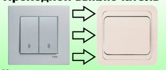
Electronic technologies cover a wide range of household spheres. There are practically no restrictions. Even the simplest functions of a household lamp lamp switch are now increasingly performed by touch devices, rather than technologically outdated manual ones.
Electronic devices, as a rule, are classified as complex structures. Meanwhile, building a touch switch with your own hands, as practice shows, is not at all difficult. Minimal experience in designing electronic devices is quite enough for this.
We suggest you understand the structure, functionality and connection rules of such a switch. For DIY enthusiasts, we have prepared three working diagrams for assembling a smart device that can be implemented at home.
Touch switch design
The term “sensory” carries a fairly broad definition. In fact, it should be considered a whole group of sensors capable of responding to a wide variety of signals.
However, in relation to switches - devices endowed with the functionality of switches, the sensory effect is most often considered as an effect obtained from the energy of the electrostatic field.
This is approximately how we should consider the design of a light switch, created on the basis of a sensor mechanism. A light touch of the fingertip to the surface of the front panel turns on the lighting in the house
An ordinary user just needs to touch such a contact field with his fingers and in response he will receive the same switching result as a standard familiar keyboard device.
Meanwhile, the internal structure of sensor equipment differs significantly from a simple manual switch.
Typically, such a design is built on the basis of four working units:
- protective panel;
- contact sensor-sensor;
- electronic board;
- device body.
The variety of sensor-based devices is extensive. Models with the functions of conventional switches are available. And there are more advanced developments - with brightness controls, monitoring the ambient temperature, raising the blinds on the windows and others.
Structurally, the touch switch looks like this: 1 – protective panel made of tempered glass; 2 – board for placing sensor elements; 3 – textolite panel with a wired circuit of the device electronics; 4 – body (chassis) of the switch (+)
Not only are all these types of switches controlled by a light touch, but there are also switches with remote control. That is, the user can turn off the lamp or dim the brightness of the lamps of the device without making unnecessary movements in the form of moving from the resting place to the switch.
Technical characteristics of “TTP223”:
- DC supply voltage, V: 2 – 5.5
- Current consumption (at rest, at VCC = 3 V), μA: 70
- Current consumption (when triggered, at VCC = 3 V), mA: 5
- Current consumption (at rest, at VCC = 5 V), μA: 130
- Current consumption (when triggered, at VCC = 5 V), mA: 16
- Output level (at VCC= 3 V), V: 2.6 (high) / 0 (low)
- Output level (at VCC=5 V), V: 4 (high) / 0 (low)
- maximum response time (at VCC= 3 V), mS: 220
- Board dimensions, mm: 11*15
Device options and capabilities
Switches with a timer clearly deserve special consideration.
There are traditional characteristics here, such as:
- silent operation;
- interesting design;
- safe use.
In addition to all this, another useful feature is added - a built-in timer. With its help, the user is able to control the switch programmatically. For example, set on and off times in a certain time range.
A unique option for developing a switch with integrated timer functionality. With the help of such devices, it is possible to control lighting at a strictly specified time. Electricity savings are obvious
As a rule, such devices have not only a timer, but also an accessory of another kind - for example, an acoustic sensor.
In this embodiment, the device works as a motion or noise controller. It is enough to raise your voice or clap your palms and the lamps in the apartment will light up with a bright light.
By the way, in case the brightness is too high, there is another functionality - dimmer adjustment. Touch-type switches equipped with a dimmer allow you to control the light intensity.
Modification of touch devices – acoustic switch. It operates according to a slightly different method, but is also a device that supports technologies for using sensors. In this case, the sensor element is a sensitive microphone
True, there is one caveat for such developments. Dimmers, as a rule, do not support the use of fluorescent and LED lamps in luminaires. But eliminating this shortcoming is most likely a matter of time.
Read more about the types of “smart” light switches in this article.
Switch classification
To choose the right communicator, you should proceed from the purpose of the room, the number and characteristics of the lamps. According to the voltage parameter, the devices are:
- 220 V is the standard for most devices;
- 12 V - suitable for LED strips and some other types of illuminators.
Depending on the number of connected light sources, single, double, and triple switches are used. It is more convenient to control a larger quantity using a remote control.
By type of key we can distinguish:
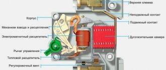
- with an electromagnetic relay - the closure occurs mechanically, so the contacts burn over time;
- equipped with a triac - a semiconductor device.
Types of sensing element in household switches:
- capacitive - requires a light touch;
- optical - reacts to movement or light level;
- high-frequency - tuned to presence, room occupancy (volume), movement.
Additional functions:
- motion, volume, sound sensors;
- wireless control;
- smooth decrease in brightness when turned off;
- timer.
Touch switches expand lighting capabilities, simplify control, and save time and energy costs. They can be stand-alone or mounted in lamp housings: floor lamps, table lamps, LED profiles.
Rules for connecting the device
The technology for installing such devices, despite the perfection of the designs, has remained traditional, as is provided for standard light switches.
Typically, there are two terminal contacts on the back of the product body - input and load. They are indicated on foreign-made devices with the markers “L-in” and “L-load”.
The technology for connecting devices is not much different from the standard. Main operating terminals: L1 (Load) – voltage phase connection line; L (In) – load voltage output line; COM – device interface terminal (+)
These symbols should be clear even to an inexperienced user. However, in any case, it is recommended to refer to the device passport before installing it. Switching in the device circuit is carried out via a phase line.
That is, a phase is supplied to the “L-in” input - a phase conductor is connected. And the voltage for the load is removed from the “L-load” line - in particular, for the lamp lamp.
Meanwhile, the designs of touch switches can provide for the connection of several independent loads. On such devices the number of terminals for connection increases.
Additionally, with the “L-in” input voltage terminal, there are already two or even three holes for the “L-load” load. They are usually marked something like this: “L1-load”, “L2-load”, etc.
Full layout of the switch: 1 – load output terminal; 2 – protective panel; 3 – spring mechanism for fastening conductors; 4 – information about the manufacturer; 5 – fireproof housing; 6 – dual control interface; 7 – screw hole (+)
The installation of touch switches is also virtually no different from the standard version. The design of the switches is made for placement in traditional socket boxes. The chassis of the working mechanism of the device is usually secured with screws.
Installation safety
Before installation, be sure to turn off the power to the network by lowering the circuit breaker switch in the distribution panel. Touch communicators are mounted without a front panel. The polarity rule is observed. If there is a grounding wire in the line, it is connected to the marked contact. The ends of the multi-core cable are crimped or crimped to secure tightly and avoid overheating.
Do not use devices that are clearly damaged or not designed for the specified network load. Homemade touch-sensitive light switches do not always withstand 220 V - most home circuits are designed for low-voltage consumers.
Do not begin installation before reading the manufacturer's instructions.
DIY switch on sensors
Buying a touch-type switch for home use is, of course, not a problem. However, the cost of these, a kind of intelligent, devices starts from 1500-2000 rubles. And this is the price of not the most advanced designs. Therefore, the logical question seems to be: is it possible to make sensory switching of light with your own hands?
For people who are more or less familiar with the theory of electrical engineering, building a switch using a sensor is a completely doable job. There are a lot of circuit solutions for this.
Scheme of a touch switch on a trigger
Many manufacturing schemes for devices of this type are simple and straightforward. Let's consider one of the many solutions that you can implement yourself for use at home.
This design of a switch with two sensors is priced on the market at RUB 1,600. a piece. If you have the skills, you can always build something similar with your own hands. At the same time, the cost of components is approximately five times lower
The K561TM2 series microcircuit, widely used in amateur radio practice, is the main link of a touch switch that you assemble yourself.
The K561TM chip is a trigger, the state of which can be changed by applying a control signal to its input. This property is successfully used to implement the switch function.
The input circuit is built with the addition of a field-effect transistor V11, which provides high sensitivity to the input and additionally well isolates the input from the output.
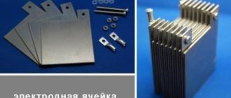
The sensor element E1 of the circuit is made in the form of a metal plate and is connected to the input of the “field device” through a resistor with a high resistance. This ensures the safety of the device for the user in terms of possible electric shock.
Diagram of the device for DIY assembly. Just one microcircuit, a pair of transistors and one thyristor are required to assemble a full-fledged touch switch. The device works no worse than an industrial one (+)
The output part of the circuit is built on a combination of bipolar transistor VT2 - current thyristor VS1. The transistor amplifies the signal coming from the microcircuit, and the thyristor acts as a switch. The lighting device that needs to be controlled is connected to the thyristor circuit.
The scheme works like this:
- The user touches the metal plate (sensor).
- Static electricity enters the VT input.
- The field effect transistor switches the trigger.
- The trigger output signal is amplified by VT2 and opens the thyristor.
- The lamp in the thyristor circuit lights up.
If the user touches the sensor again, all operations are repeated, but with the reverse mode switching. Everything is simple and effective.
This circuit solution can be used to control lamps where the total power of incandescent lamps is no higher than 60 W.
If it is necessary to switch more powerful light devices, you can supplement the thyristor with a volumetric cooling radiator. It is recommended to use metal for the sensor from a series of materials that conduct current well. The best option is silver-plated copper.
Circuit based on an infrared sensor
A light switch circuit is available for self-assembly, where an IR sensor is used as a sensor. Available and inexpensive electronic components are also used here.
In terms of complexity, this option is designed for electronics engineers who are just starting their careers.
Another circuit solution for a touch-type switch device. It also has a minimum of electronic components, but requires careful configuration to ensure quality performance. This requires extensive experience as an electronics engineer (+)
The basic electronics in this solution are two microcircuits and the following elements:
- regular LED - HL1;
- infrared LED - HL2;
- photodetector - U1;
- relay - K1.
A pulse generator is assembled on the basis of the inverter chip DD1, and a system counter operates on the basis of the DD2 chip.
Under certain circumstances, for example, when a biological object appears within the range of the infrared LED, a pair of IR LED and photodetector is activated. Based on transistor VT1, a control signal appears, which turns on relay K1. The lamp in circuit K1 lights up.
If there is no movement of objects within the coverage area of the infrared sensor, after 20 minutes of inactivity the counter will count the number of pulses from the flashing HL1 LED sufficient to turn off the relay. The lamp will turn off. The waiting time (in this case 20 minutes) is determined by the selection of circuit elements.
The simplest circuit using transistors and relays
The most simplified solution is a diagram for self-assembly of a touch-type device, which is presented below.
A diagram simplified to the minimum for building a touch switch with your own hands. However, subject to precise selection of radioelements, the device can operate quite efficiently and reliably.
It is permissible to use almost any type of relay here. The main criterion is the operating voltage range of 6-12 volts and the ability to switch loads in a 220 volt network.
The sensor element is made by cutting out a sheet of foil getinax. Transistors can also be used in any series, similar in parameters to those indicated, for example, the common KT315.
In essence, this simple circuit represents a conventional signal amplifier. When you touch the surface of the sensor based on transistor VT1, a potential appears that is sufficient to open the emitter-collector junction.
Next, transition VT2 opens and the supply voltage is supplied to relay coil K1. This device is triggered, its contact group closes, which leads to the light device turning on.
If you don’t want to experiment and assemble the device yourself, you can buy a ready-made switch and install it yourself. All the necessary information about selecting and connecting a touch switch is presented here.
Varieties
Touch switches, both conventional and pass-through, are used in many equipment control devices. They are often mounted in various consoles and in all those units and equipment that require manual control. In everyday life, to ensure reliability, you can find sensor systems in washing machines, microwave and conventional ovens, televisions, radios, and telephones. They are found in almost all household devices that make human life easier.
In addition to the usual use as a switch, dimmer controllers have also become widespread. In appearance, this is a drawn thickening stripe or circle on the body of the device. By sliding your finger along which, and depending on the current position on the scale, you can adjust the volume or brightness, set the time or set any average parameters.
Like classic ones, touch switches are available in a single-channel design, or with the ability to connect several current consumers. Each of which is separately controlled from one connector.
Motion detectors are mistakenly classified as this type of switching device. They of course detect the movement of an object within the range of the sensor, and can be configured for use as a conventional current breaker. But such use of a rather complex device does not justify itself economically. In addition, their failure rate and the frequency of false alarms are higher than that of classic versions of touch switches.
Conclusions and useful video on the topic
This review allows you to take a closer look at light switches, which are quickly gaining popularity in society.
Touch switches marked by the Livolo product brand - what these designs are and how attractive they are to the end user. A video guide to the new type of switches will help you get answers to the questions:
Concluding the topic of touch switches, it is worth noting the active development in the development and production of switches for household and industrial use.
Light switches, seemingly the simplest designs, are so advanced that now you can control the light with a voice code phrase and at the same time receive complete information about the state of the atmosphere inside the room.
Do you have anything to add or have questions about assembling the touch switch? You can leave comments on the publication, participate in discussions and share your own experience of using such devices. The contact form is located in the lower block.
STM8/STM32 Touch-Sensing Library
The freely available STM8/STM32 Touch-Sensing Library greatly simplifies the implementation of touch applications based on STM8/32 controllers [8]. The libraries allow you to organize not only interrogation of capacitive sensors, but also implement signal processing in order to reduce the influence of external interference and increase operational stability.
The STM8/STM32 Touch-Sensing Library is provided as open source code in the C language, compatible with all popular compilers (MISRA, Cosmic, IAR, Raisonance C) with examples of use. The structure of the libraries for 8- and 32-bit controllers is almost identical - a set of high-level functions for interacting with application programs, a set of auxiliary services, device drivers specific to each of the controller families, and the core of the library, which is responsible for processing information from touch buttons, calibration, filtering signals, monitoring changes in the environment.
In addition to polling the capacitive button, the library provides signal processing algorithms that make it possible to compensate for the negative influence of factors such as temperature, external environment, and changes in supply voltage.
The core of the library is two finite state machines - a central state machine that controls the sequence of actions, and a touch button machine that tracks changes in its state, a copy of which is launched for each of the installed buttons.
From the point of view of an application programmer, working with the library consists of initializing and calling the necessary functions (Figure 9). The nice thing is that, with the exception of the driver level, the function names and methods of calling them are the same for the 8- and 32-bit versions, making it easy to migrate applications between these platforms.
Rice. 9. Structure of the STM8/STM32 Touch-Sensing Library
The STM8 Touch-Sensing Library for 8-bit STM8 controllers allows you to use their I/O lines to work with touch buttons with a minimum number of external components and memory costs. Button polling is implemented either by measuring the time constant of the RC chain (up to 24 buttons and two lines or scroll wheels), or by the charge transfer principle (up to 16 buttons and two lines or scroll wheels). Polling using the first method is available for any STM8 or STM8L controller, while the charge transfer method requires a special module in the controller and is currently implemented for the STM8L101x and STM8L15x series.
The programmer has access to polling, filtering, and calibration functions that make it quite easy to optimize the operation of touch applications in completely different conditions. So, with only three sensitive capacitive channels, you can get a scrollbar (or scroll wheel) resolution of 8 bits - 256 levels, and this is only on an 8-bit core, while maintaining the controller's ability to work with other peripheral devices, such as LED indicators, LCD displays, work with communication interfaces!
For STM8L15x series devices, it is possible to support both software polling using the charge transfer method and library initialization with hardware polling support.
For STM32, the supported method for working with capacitive sensors is the method based on charge transfer and is implemented on controllers of the STM32L family.
Electronic telegraph key
The electronic telegraph key on one K561J1E5 chip (Fig. 14) is made according to the traditional scheme for such keys [RL KB and VHF 1/96-23]. The relaxation generator is assembled on logic elements with different RC circuits responsible for generating dashes and dots.
Rice. 14. Scheme of an electronic telegraph key.
When you press the telegraph key (closing the charging circuit), the group of capacitors C1 - SZ (dash) or C2, SZ (dot) is charged. When the voltage at the input of logic element DD1.1 exceeds a certain threshold level, it will switch and the output will be set to logical zero.
The charging process of the capacitors will be interrupted, and they will begin to discharge through resistances R2 and R3. When the voltage on the capacitors drops below a certain value, the first logic element will switch again, and the process of charging/discharging the capacitors will repeat.
This process will continue as long as the contact group of the telegraph manipulator is closed. The duration of the dots and dashes is determined by the time constants of the charging and discharging circuits (RC). Capacitors C1 - SZ must have low leakage currents.
For sound indication of generated telegraph signals, a generator is designed, made on the third and fourth elements of the microcircuit.
The generator is loaded onto a piezoceramic emitter of the ZP-19 type. When using an inductive emitter (telephone capsule) in series with it, it is necessary to include a separating capacitor with a capacity of more than 0.1 μF.
Simultaneously with the sound, a light indication on the NI LED (AL307) was introduced into the circuit, which allows you to visually monitor the presence of telegraph parcels. To switch the circuits of the transmitting device, a buffer cascade on transistor VT1 (KT315), loaded on a relay, is used.
As with other simple telegraph keys that use a similar method of forming dots and dashes, this design has the same disadvantages: the need to adjust the dot/dash duration ratio with resistance R1 when the transmission speed changes.
The mechanical part of the manipulator can be made from a piece of hacksaw blade with adjacent contact groups. As such contacts, you can use the contacts of a disassembled large relay.
Models with continuously adjustable lighting intensity
If you need a device that allows you to change the brightness level gradually, you should pay attention to touch switches with dimmers.
Some of these devices can be adjusted using a remote control. You can adjust the brightness of sconces or LED lighting without getting up from your chair. The touch switch with this device extends the life of incandescent lamps by eliminating the effect of sudden voltage supply. The connection diagrams for some devices require a power supply or dimmer. This switch device is ideal for controlling the LED strip circuit.
Simple metal detector
A metal detector based on the DD1 K561ЛE5 microcircuit, made according to the traditional scheme for comparing the frequencies of the reference and search oscillators [P 8/89-65], is shown in Fig. 12.
Rice. 12. Metal detector diagram.
The frequency of the reference oscillator is determined by the capacitance of capacitor C1 and the total resistance of resistors R1 and R2.
The frequency of the search generator depends on the parameters of the LC circuit of the search coil (L1, C2). As the search coil approaches a metal object, its inductance changes, changing the frequency of the search oscillator.
Signals from both generators through decoupling capacitors C4 and C5 are supplied to a diode detector made according to a voltage doubling circuit.
The load of the detector is a high-resistance telephone capsule BF1, and a difference frequency signal is isolated in it. When using a low-impedance telephone capsule, an additional amplification stage may be required. Capacitor C6 shunts the high-frequency components of the mixed signals to the common wire.
The search coil is placed inside an aluminum or copper open ring with a diameter of 200 mm. Tube diameter - 8 mm. For winding, a wire was used, for example, PELSHO with a diameter of 0.5 mm.
The number of turns is determined according to the principle of “how many will go in”. The coil leads are connected to the circuit, and the tube itself is connected to a common bus.
Setting up a metal detector involves setting the frequency of the reference oscillator until low-frequency sound signals appear in the telephone capsule. In this case, you may have to select the capacitance of capacitor C1 or C2.