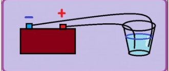
When charging a battery, there are requirements for the voltage and current provided by the power adapter. A situation may arise when its electrical parameters do not correspond to those needed for this procedure. To limit the current, it is necessary to make additions to the circuit used. To do this, you need to understand how the charger works and what physical processes occur during operation.
Battery charging procedure Source avtoshef.com
What is current strength?
Electric current is the ordered movement of charged particles inside a conductor with the obligatory presence of a closed circuit.
The appearance of current is due to the movement of electrons and free ions that have a positive charge.
As they move, charged particles can heat the conductor and have a chemical effect on its composition. In addition, the current can influence neighboring currents and magnetized bodies.
Current strength is an electrical parameter that is a scalar quantity. Formula:
I=q/t, where I is current, t is time, and q is charge.
It is also worth knowing Ohm's law, according to which current is directly proportional to U (voltage) and inversely proportional to R (resistance).
I=U/R.
There are two types of current - positive and negative.
Below we will consider what this parameter depends on, how to increase the current strength in the circuit, in the generator, in the power supply and in the transformer.
We will provide proven recommendations that will allow you to solve your problems.
About regulators
Structurally, tablets that control the voltage in the generator are capable of increasing the current to 13.6 volts. It is known that there are two schemes for connecting the regulator: old and new.
The old circuit is a more reliable option, which does not increase the voltage too much, but also does not allow it to drop to critical values. But the new one - although it is completely copied from the old one, has many shortcomings.
Chronic undercharging of the battery is precisely the drawback of the new scheme. Starting the engine becomes problematic in the cold season. Owners have to install preheaters or come up with something else.
Poor quality regulators force the battery to absorb energy only in the summer, i.e., at above-zero temperatures. In winter, especially if you make short trips by car, the battery does not have time to warm up, at least to 0, and periodically discharges.
Experienced motorists recommend driving for at least 20-30 minutes in winter to restore the battery.
So how is the problem solved? Obviously, the best option is to increase the voltage in the on-board network, but how to do this? It is necessary to make the tablet “believe” that there is supposedly low voltage in the network. Thus, we will ensure that the gene produces the missing voltage.
Low voltage in the vehicle's on-board network can be caused by the presence of a large number of consumers. For example, if you use a powerful speaker system with a subwoofer and amplifier, voltage dips are inevitable.
Instead of a diode, you can also use special regulators that produce three voltage values, depending on the air temperature: 13.2, 13.9 and 14.5 volts. There are three modes: summer, spring/autumn and winter.
We recommend viewing the table, which shows data on the normal charge of the battery and the standard operation of the generator.
| Battery charge level | Charge the battery with a charger | Generator operation |
| 12.72 volts - 100% | If the EMF is less than 12.6 V | norm - from 13.6 V - to 14.4 V |
| 12.50 volts - 75% | Uload - less than 9 V (load fork) | less than 13.6 V – undercharge (bad) |
| 12.35 volts - 50% | Electrolyte density—less than 1.25 g/cm | more than 14.4 V – overcharge. (also bad) |
| 12.10 volts - 25% |
The effectiveness of the diode, which increases the voltage in the on-board network, is beyond doubt. Almost all experienced motorists and owners of domestic models do this. After this, the car will be easy to start not only in summer, but also in winter. High current – accurate charging.
What does current strength depend on?
To increase I in a circuit, it is important to understand what factors can influence this parameter. Here we can highlight the dependence on:
- Resistance. The smaller the parameter R (Ohm), the higher the current in the circuit.
- Voltages. Using the same Ohm's law, we can conclude that as U increases, the current strength also increases.
- Magnetic field strength. The larger it is, the higher the voltage.
- Number of coil turns. The greater this indicator, the greater U and, accordingly, the higher I.
- The power of the force that is transmitted to the rotor.
- Diameter of conductors. The smaller it is, the higher the risk of heating and burning out the supply wire.
- Power supply designs.
- The diameter of the stator and armature wires, the number of ampere-turns.
- Generator parameters - operating current, voltage, frequency and speed.
Preliminary work
Before you begin work to reduce the current in the electrical circuit, you need to take care of the safety of the workplace. To do this, make sure that the area is completely protected from electric shock. In addition, it is important to remember that before starting work it is necessary to disconnect all electrical circuits.
Since the current strength depends on two parameters - resistance and voltage, there are several simple ways to reduce this value. The most common and simple method is to add additional resistance to the network or connect some device to the open circuit that will provide this function.
To measure the necessary indicators, you will need a multimeter. The voltage supplied to the electrical circuit must be turned off. To do this, simply switch the switch to the required mode. After the device indicator or multimeter indicators indicate that the network is de-energized, you can begin to work. Now you need to determine the resistance that the input device provides. By switching the multimeter to ohmmeter mode, you can find out this parameter. If you do not have the necessary equipment, then you can find out the resistance by adding up all the resistance indicators in a given circuit.
How to increase the current in a circuit?
There are situations when it is necessary to increase I, which flows in the circuit, but it is important to understand that measures need to be taken to protect electrical appliances; this can be done using special devices.
Let's look at how to increase the current using simple devices.
To complete the work you will need an ammeter.
Option 1.
According to Ohm's law, current is equal to voltage (U) divided by resistance (R). The simplest way to increase force I, which suggests itself, is to increase the voltage supplied to the input of the circuit, or to reduce the resistance. In this case, I will increase in direct proportion to U.
For example, when connecting a 20 Ohm circuit to a power source with U = 3 Volts, the current value will be 0.15 A.
If you add another 3V power source to the circuit, the total value of U can be increased to 6 Volts. Accordingly, the current will also double and reach a limit of 0.3 Amperes.
The power supplies must be connected in series, that is, the plus of one element is connected to the minus of the first.
To obtain the required voltage, it is enough to connect several power sources into one group.
In everyday life, constant U sources combined into one group are called batteries.
Despite the obviousness of the formula, practical results may differ from theoretical calculations, which is due to additional factors - heating of the conductor, its cross-section, the material used, and so on.
As a result, R changes towards an increase, which leads to a decrease in force I.
Increasing the load in the electrical circuit can cause overheating of the conductors, burnout, or even a fire.
That is why it is important to be careful when operating devices and take into account their power when choosing a cross-section.
The value of I can be increased in another way by reducing the resistance. For example, if the input voltage is 3 Volts and R is 30 Ohms, then a current of 0.1 Ampere passes through the circuit.
If you reduce the resistance to 15 Ohms, the current strength, on the contrary, will double and reach 0.2 Amperes. The load is reduced to almost zero during a short circuit near the power source, in this case I increases to the maximum possible value (taking into account the power of the product).
Resistance can be further reduced by cooling the wire. This effect of superconductivity has long been known and is actively used in practice.
To increase the current in a circuit, electronic devices are often used, for example, current transformers (as in welders). The strength of variable I in this case increases with decreasing frequency.
If there is active resistance in the AC circuit, I increases as the capacitance of the capacitor increases and the inductance of the coil decreases.
In a situation where the load is purely capacitive in nature, the current increases with increasing frequency. If the circuit includes inductors, the force I will increase simultaneously with the decrease in frequency.
Also read - how electric current acts on the human body.
Option 2.
To increase the current strength, you can focus on another formula, which looks like this:
I = U*S/(ρ*l). Here we only know three parameters:
- S—wire cross-section;
- l is its length;
- ρ is the electrical resistivity of the conductor.
To increase the current, assemble a chain containing a current source, a consumer and wires.
The role of the current source will be performed by a rectifier, which allows you to regulate the EMF.
Connect the chain to the source, and the tester to the consumer (pre-set the device to measure current). Increase the EMF and monitor the indicators on the device.
As noted above, as U increases, it is possible to increase the current. A similar experiment can be done for resistance.
To do this, find out what material the wires are made of and install products that have lower resistivity. If you cannot find other conductors, shorten the ones already installed.
Another way is to increase the cross-section, for which it is worth mounting similar conductors parallel to the installed wires. In this case, the cross-sectional area of the wire increases and the current increases.
If we shorten the conductors, the parameter we are interested in (I) will increase. If desired, options for increasing the current can be combined. For example, if the conductors in the circuit are shortened by 50% and U is raised by 300%, then the force I will increase 9 times.
Video description
How to use a light bulb to limit the rectifier current and protect the transformer from short circuit.
When working with car batteries, you can often encounter the use of non-standard chargers. In addition, we must take into account that it can be charged on the go. In all these cases, the current strength can vary within wide limits.
In particular, when recharging while the engine is running, the starting current can be very significant during the first seconds. That is, its strength changes dynamically, so the adjustment must be active, depending on the values of the parameters at this moment.
The principle of battery charging Source ice-people.ru
How to increase the current in the power supply?
On the Internet you can often come across the question of how to increase I in the power supply without changing the voltage. Let's look at the main options.
Situation No. 1.
A 12 Volt power supply operates with a current of 0.5 Amperes. How to raise I to its maximum value? To do this, a transistor is placed in parallel with the power supply. In addition, a resistor and stabilizer are installed at the input.
Find out more - how to check a transistor with a multimeter for serviceability.
When the voltage across the resistance drops to the required value, the transistor opens, and the rest of the current flows not through the stabilizer, but through the transistor.
The latter, by the way, must be selected according to the rated current and a radiator installed.
In addition, the following options are possible:
- Increase the power of all elements of the device. Install a stabilizer, a diode bridge and a higher power transformer.
- If there is current protection, reduce the value of the resistor in the control circuit.
Situation No. 2.
There is a power supply for U = 220-240 Volts (at the input), and at the output a constant U = 12 Volts and I = 5 Amperes. The task is to increase the current to 10 Amps. In this case, the power supply should remain approximately the same dimensions and not overheat.
Here, to increase the output power, it is necessary to use another transformer, which is converted to 12 Volts and 10 Amps. Otherwise, the product will have to be rewound yourself.
In the absence of the necessary experience, it is better not to take risks, because there is a high probability of a short circuit or burnout of expensive circuit elements.
The transformer will have to be replaced with a larger product, and the damper chain located on the DRAIN of the key will also have to be recalculated.
The next point is replacing the electrolytic capacitor, because when choosing a capacitance you need to focus on the power of the device. So, for 1 W of power there are 1-2 microfarads.
It is also recommended to change the diodes with rectifiers. In addition, it may be necessary to install a new rectifier diode on the low side and increase the capacitor capacity.
After such a modification, the device will heat up more, so installing a fan is not necessary.
Tips for choosing
Before purchasing a voltage stabilizer, you need to decide whether it is needed or not, but for preventive purposes it is still worth installing, since the voltage in electrical networks often varies.
When choosing a mini-transformer, the following characteristics are taken into account:
- Number of phases.
- Output power.
- Weight of the device.
- Transformer dimensions.
- Operational life.
- Operating voltage range.
- Speed of reaction to power surges.
The load of specific devices must be clarified. Single-phase transformers are purchased for low-power household appliances, three-phase stabilizers are purchased for a large number of devices that require load distribution.
One of the most popular and sought-after transformers is the Resanta ASN, a single-phase digital stabilizer with an affordable price of 2,600 rubles. This transformer is mounted on the wall.
A more expensive and reliable model is the Shtil stabilizer. Its approximate cost is 4,000 rubles. The Shtil stabilizer is optimally suited for protecting electronic equipment and household appliances at alternating voltage.
How to increase the current in the charger?
When using chargers, you may notice that chargers for a tablet, phone or laptop have a number of differences. In addition, the speed at which devices are charged may also vary.
Here a lot depends on whether an original or non-original device is used.
To measure the current that goes to your tablet or phone from the charger, you can use not only an ammeter, but also the Ampere app.
Using the software, it is possible to determine the charging and discharging speed of the battery, as well as its condition. The application is free to use. The only drawback is advertising (the paid version does not have it).
The main problem with charging batteries is the low current of the charger, which is why the time to gain capacity is too long. In practice, the current flowing in the circuit directly depends on the power of the charger, as well as other parameters - cable length, thickness and resistance.
Using the Ampere application, you can see at what current the device is charged, and also check whether the product can charge at a higher speed.
To use the capabilities of the application, just download it, install and run it.
After this, the phone, tablet or other device is connected to the charger. That's all - all that remains is to pay attention to the current and voltage parameters.
In addition, you will have access to information about the battery type, U level, battery condition, as well as temperature conditions. You can also see the maximum and minimum I that occur during the cycle.
If you have several chargers at your disposal, you can run the program and try charging each of them. Based on the test results, it is easier to select a charger that provides the maximum current. The higher this parameter is, the faster the device will charge.
Current measurement isn't the only thing Ampere can do. With its help, you can check how much I is consumed in standby mode or when turning on various games (applications).
For example, after turning off the display brightness, deactivating GPS or data transfer, it is easy to notice a decrease in load. Against this background, it is easier to conclude which options drain the battery the most.
What else is worth noting? All manufacturers recommend charging devices with “native” chargers that produce a certain current.
But during operation, there are situations when you have to charge your phone or tablet with other chargers that have more power. As a result, the charging speed may be higher. But not always.
Few people know, but some manufacturers limit the maximum current that the device’s battery can accept.
For example, a Samsung Galaxy Alpha device comes with a 1.35 Ampere charger.
When connecting a 2-amp charger, nothing changes - the charging speed remains the same. This is due to a limitation set by the manufacturer. A similar test was carried out with a number of other phones, which only confirmed the guess.
Taking into account the above, we can conclude that non-native chargers are unlikely to cause harm to the battery, but can sometimes help with faster charging.
Let's consider another situation. When charging a device via a USB connector, the battery gains capacity more slowly than when charging the device from a conventional charger.
This is due to the limitation of the current that a USB port can supply (no more than 0.5 Ampere for USB 2.0). When using USB3.0, the current increases to 0.9 Ampere.
In addition, there is a special utility that allows the “troika” to pass a larger I through itself.
For devices like Apple, the program is called ASUS Ai Charger, and for other devices - ASUS USB Charger Plus.
Charging methods
When charging various computer and home gadgets, direct current is usually directly used. But for car batteries, it is also possible to use alternating current. When charging them, you need to consider the following:
- Using a constant using the selected method ensures the optimal value. As the charge increases, the current will decrease until it drops to zero and the procedure is completed.
- When using alternating current, the battery is charged until the potential difference reaches 14 V. At this point, the current must be halved. After the indicator increases to 15 V, charging is stopped.
In both cases, the initial current must be equal to one tenth of the capacity value, expressed in Ampere * hour.
A block of several batteries Source mysku.ru
How to increase the current in a transformer?
Another question that worries electronics enthusiasts is how to increase the current strength in relation to the transformer.
Here are the following options:
- Install a second transformer;
- Increase the diameter of the conductor. The main thing is that the cross-section of the “iron” allows it.
- Raise U;
- Increase the cross-section of the core;
- If the transformer operates through a rectifier device, it is worth using a product with a voltage multiplier. In this case, U increases, and with it the load current also increases;
- Buy a new transformer with a suitable current;
- Replace the core with a ferromagnetic version of the product (if possible).
A transformer has a pair of windings (primary and secondary). Many output parameters depend on the wire cross-section and the number of turns. For example, there are X turns on the high side and 2X on the other side.
This means that the voltage on the secondary winding will be lower, as will the power. The output parameter also depends on the efficiency of the transformer. If it is less than 100%, U and the current in the secondary circuit decrease.
Taking into account the above, the following conclusions can be drawn:
- The power of the transformer depends on the width of the permanent magnet.
- To increase the current in the transformer, a decrease in R load is required.
- The current (A) depends on the diameter of the winding and the power of the device.
- In case of rewinding, it is recommended to use thicker wire. In this case, the wire mass ratio on the primary and secondary windings is approximately identical. If you wind 0.2 kg of iron on the primary winding and 0.5 kg on the secondary winding, the primary will burn out.
How do you increase and decrease voltage?
Increasing and decreasing voltage is carried out using transformers
.
The transformer consists of two coils of insulated wire wound on a common steel core (Fig. 16.4).
One coil (called the primary winding) is supplied with alternating current of one voltage, and the other coil (called the secondary winding) is supplied with alternating current of a different voltage.
Rice. 16.4. Step-up and step-down transformers.
It is concentrated mainly inside the steel core, so both windings are threaded with the same
variable magnetic flux.
Therefore, due to the phenomenon of electromagnetic induction in each turn of each winding
the same induced emf occurs.
The total emf in each of the coils is equal to the sum of the emf in all its turns, since the turns are connected to each other in series. Therefore, the ratio of voltages in the secondary and primary windings is equal to the ratio of the number of turns in them: For example, if the secondary winding has 10 times more turns than the primary, the voltage in the secondary winding will be 10 times greater than in the primary.
If the voltage in the secondary winding of the transformer is greater than in the primary, it is called step-up
, and if less, then
downward
.
The main consumers of electricity are manufacturing and transport. Domestic needs account for no more than 5-10% of all electricity produced.
Rice. 16.5. The main stages of production, transmission and consumption of electricity.
Encyclopedia articles
How to increase the current in the generator?
The current in the generator directly depends on the load resistance parameter. The lower this parameter, the higher the current.
If I is higher than the nominal parameter, this indicates the presence of an emergency mode - frequency reduction, generator overheating and other problems.
For such cases, protection or disconnection of the device (part of the load) must be provided.
In addition, with increased resistance, the voltage decreases, and U increases at the generator output.
To maintain the parameter at an optimal level, regulation of the excitation current is provided. In this case, an increase in the excitation current leads to an increase in the generator voltage.
The network frequency must be at the same level (constant).
Let's look at an example. In a car generator, it is necessary to increase the current from 80 to 90 Amperes.
To solve this problem, you need to disassemble the generator, separate the winding and solder the lead to it, followed by connecting the diode bridge.
In addition, the diode bridge itself is changed to a part with higher performance.
After this, you need to remove the winding and a piece of insulation in the place where the wire is to be soldered.
If there is a faulty generator, the lead is bitten off from it, after which the legs of the same thickness are built up using copper wire.
After soldering, the joint is insulated with heat shrink.
The next step is to buy an 8-diode bridge. Finding it is a very difficult task, but you have to try.
Before installation, it is advisable to check the product for serviceability (if the part is used, a breakdown of one or more diodes is possible).
After installing the bridge, attach the capacitor, and then a 14.5-volt voltage regulator.
You can purchase a pair of regulators - 14.5 (German) and 14 Volts (domestic).
Now the rivets are drilled out, the legs are unsoldered and the tablets are separated. Next, the tablet is soldered to a domestic regulator, which is fixed with screws.
All that remains is to solder the domestic “pill” to the foreign regulator and assemble the generator.
Initial state of the circuit.
When turning on the circuit breaker QF1
phases “A”, “B”, “C” arrive at the upper power contacts of magnetic starters
KM1
and
KM2
and remain on duty there.
Phase “A”, which supplies the control circuits, through the control circuit protection circuit breaker SF1
and the
SB1
“Stop” button is sent to contact
No. 3
SB2
and
SB3
buttons , auxiliary contact
13NO
the KM1
and
KM2
starters , and remains on duty at these contacts. The circuit is ready for use.
The figure below shows part of the reversible circuit, namely, a wiring diagram of control circuits with real elements.