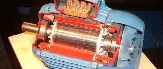
Why do you need a speed controller?
Typically, mini drills are built on the basis of conventional DC motors.
And the speed of such engines depends on the load and applied voltage. As a result, at idle speed the engine spins very strongly, and during drilling moments the engine speed fluctuates in a wide range. If you reduce the voltage on the motor when there is no load on it, you can achieve an increase in the service life of both the drills and the motors themselves. In addition, even drilling accuracy is improved. The easiest way to achieve this is to measure the current drawn by the motor.
There are many circuits of similar regulators on the Internet, but most of them use linear voltage regulators. They are massive and require cooling. In collaboration with TinyElectronicFriends, we wanted to make a compact board based on a switching stabilizer so that it could simply be “put on” the motor.
Question from a reader
Reader Alexander contacted me by email with the following request:
Good evening. I came across your blog where you repair a Bosch drill. I have a similar problem, but I have almost nothing to do with electronics. Stupidly I disassembled the trigger of a Bosch GSB 1600 RE drill. Everything worked great before, I put it together somehow, but now the soft start doesn’t work. Perhaps I’m putting the parts in the wrong order and in the wrong place. I am attaching a photo of the disassembled one. I hope this helps, the drill is good.
Photo of a disassembled Bosch drill button:
Bosch drill repair. The disassembled trigger is a button with a speed control.
Bosch drill repair. Disassembled trigger - button
I don't know how to help the reader. Maybe someone can share their experience?
Links:
I suggest reading a book that describes various curious inventions: Otto Petrik, Curiosities of Technology, Budapest 1985, 150 pp., illus.
If you liked the article, vote for it here and now:
Voting for the authors of the summer competition
- 1. Marchenko Boris Danilovich with articles on welding cores and searching for hidden wiring (49%, 29 Votes)
- 3. Sergey Pikalov with an article about wiring in construction (34%, 20 Votes)
- 2. Alexey Sidorkin with an article about repairing a Bosch drill (17%, 10 Votes)
Total voters: 59
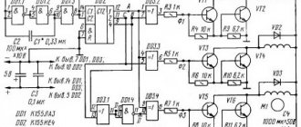
Scheme
A PWM regulator with a built-in switch MC34063 regulates the voltage on the motor.
The voltage on the shunt R7, R9, R11 is amplified by the operational amplifier and, through a comparator, supplied to the feedback input of the PWM controller. If the current is less than a certain value, then a voltage is applied to the motor, depending on the resistance setting RV1. That is, at idle speed only part of the power will be supplied to the engine, and the trimming resistor RV1 will allow you to adjust the speed at the same time.
If the signal at the output of the op-amp exceeds the voltage on the comparator, then the full supply voltage will be supplied to the motor. That is, when drilling, the engine will turn on at maximum power. The switching threshold is set by resistor RV2. A linear stabilizer is used to power the op-amp.
All components of the circuit will dissipate very little heat and it can be assembled entirely using SMD components. It can operate over a wide range of supply voltages (depending on resistance R6), and does not require controllers or speed sensors.
Power tool power regulator.
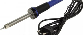
Hello! Of all the tools I have, the most used one is an angle grinder (grinder). In addition to cutting various materials, it is often used for cleaning and grinding surfaces. When working with wooden materials, flap wheels often burn the wood. Too many revolutions. Velcro circles on tiles also tend to fly off due to centrifugal force. I saw the solution to the problem as adding a speed controller to the grinder. The search criterion was the ability to be built into the tool body at the lowest cost. Micro review.
Faithfully and truly, another angle grinder has been serving me for six years now. Manufacturer DIOLD, for 125 circle. The more precise designation has been erased over time, but I don’t remember it anymore.
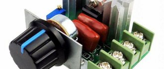
I didn't want to make a remote regulator. There is a little space in the handle. Having looked at the dimensions of the twister on the seller’s page and decided that I would cram it in after all, I ordered it.
The parcel took about a month to arrive, the track was not tracked. Performance characteristics from the product page.
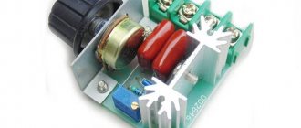
Model: 6 speeds Maximum voltage: 250 (V) Rated heating current: 6 (A) Operating temperature: 0-50 © Material: plastic.
There are not 6 speeds, of course, smooth adjustment with a potentiometer. Numbers for clarity.
Dimensions:
Length - 30 mm; Width - 17 mm; Height - 30 mm.
At one end el. characteristics.
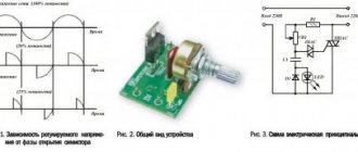
On the opposite side is the connection diagram.
Approximate electrical diagram of the device. The controller under review differs only in the presence of an adjustment potentiometer and a switch (beyond the 6th position, the electrical adjustment is turned off and mains voltage is supplied to the instrument directly).
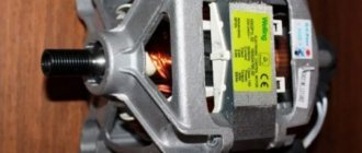
The inside of the case looks like this. The triac is used by VTV08.
Characteristics:
VRRM, V 600 IT(RMS) (max.), A 8 VDRM (max.), V 600 IFSM (max.), A 84 IFT, mA 35 dV/dt, V/µs 400 dI/dt, A/ms 4.5 TA,°C from -40 to 125 Can be used without a radiator up to 1000W
PCB board. On the reverse side there is only soldering. (I stained it with flux, the supplied wires are short)
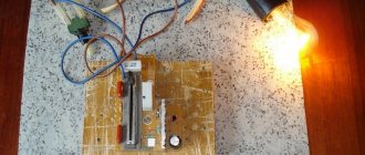
I disassembled the angle grinder. The only place for installation was here.
I sawed a hole in the body. The body of the grinder handle is made of viscous plastic. The regulator is inserted very tightly. I didn’t fasten it with anything.
The location turned out to be good. Does not interfere when working with the tool.
About 5 mm didn’t fit all the way in, not critical at all. The main thing is that it is convenient to use.
The regulator smoothly changes the voltage. Connects to the break in the supply wire. In the first position the voltage is 154 V.
In sixth position is 201 V.
My grinder is low-powered, so it stops at positions 1 and 2 when cutting metal. But from 3 onwards it works great. I got what I expected from the regulator. At work I was grinding tiles. The nozzle does not try to escape from the platform, there is less vibration and there is no such column of dust. I used a petal wheel to chamfer the end of the board, but it didn’t burn. Now the angle grinder fully lives up to its name (angle grinder). I turn on the angle grinder directly connected to the network, and then reduce the speed to the required speed. Although it starts at low speeds. Maybe in vain, well, just in case. It's on video.
A short video of work.
Thank you everyone and happy shopping!
List of components
Here is a complete list of everything needed for assembly:
- Printed circuit board (link to manufacturing files at the end of the article)
- U1 - MC34063AD, switching regulator, SOIC-8
- U2 - LM358, operational amplifier, SOIC-8
- U3 - L78L09, stabilizer, SOT-89
- D1,D3 - SS14, Schottky diode, SMA - 2 pcs
- D2 - LL4148, rectifier diode, MiniMELF
- C1 - capacitor, 10uF, 50V, 1210
- C2 - capacitor, 3.3nF, 1206
- C3, C4 - capacitor, 4.7 µF, 1206 - 2 pcs
- C5 - capacitor, 22uF, 1206
- R1-R3,R7,R9,R11 - 1 Ohm resistor, 1206 - 6 pcs.
- R4, R10 - resistor 22 kOhm, 1206 - 2 pcs.
- R5 - 1kOhm resistor, 1206
- R6 - resistor 10-27 kOhm, 1206. The resistance depends on the rated voltage of the motor used. 12V - 10kOhm, 24V - 18kOhm, 27V - 22kOhm, 36V - 27kOhm
- R8 - resistor 390 Ohm, 1206
- RV1, RV2 - subscript resistor, 15 kOhm, type 3224W-1-153 - 2 pcs.
- XS1 - terminal, 2 pins, pitch 3.81mm
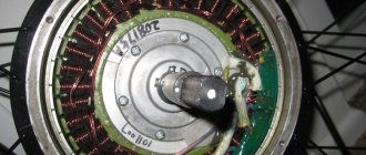
We also made a limiter ring on a 3D printer for easy installation on the engine. The download link for the STL file is at the end of the article.
Triac regulator
The triac regulator located in the start button is responsible for the speed of the installation at the time the drill is turned on. This regulator is installed in the button body and placed on a lining made of PCB. The board is designed in such a way that it has small dimensions, which allows it to be located one hundred percent in the trigger space. After pressing the power button, an immediate break occurs in the device regulator; under such circumstances, the circuit is closed in a short time. And the regulator does not have the ability to influence voltage variation, but in this case the rms voltage level is subject to change.
Assembly and configuration
Everything is assembled quite simply.
The contact pads are designed for hand soldering. It is worth starting assembling the board itself by installing all the components on the side of the board without trimmers, and then on the reverse side. It is easier to install the terminal last. The R6 rating is selected according to the rated voltage of your motor. In this device, it is important to control the position of the key on the microcircuits and the polarity of the diodes. All other components are non-polar. Place a spacer between the board and the motor above so that the board does not touch the motor. The board itself is placed directly on the engine lamellas. Check the polarity of the motor connection several times so that it turns to the right, and then solder the contacts.
Contacts for supplying voltage, the board input is labeled “GND” and “+36V”. The negative of the input voltage source is connected to the “GND” contact, and the positive to “+36V”. The power supply voltage must match the rated voltage of the motor.
Setting up the controller is very simple:
- Set the regulator response threshold to the maximum using resistor RV2
- Set resistor RV1 to the optimal engine speed in idle mode
- Set the response threshold with resistor RV2 so that when the slightest load appears, the voltage on the motor increases
Schematic diagram
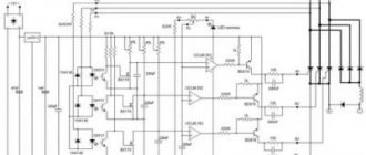
This solves the problem of low power of such stabilizers. Nowadays, most of us cannot afford to purchase a factory-made (Si-mistor) network stabilizer at the price of a good computer. Let's consider the practical design of the RHF, the diagram of which is shown in Fig. 1.
Rice. 1. Schematic diagram of the speed controller of the shaft of an electric drill powered by 220V.
The basis of the circuit was taken from [3], since the circuit itself turned out to be ineffective in practice. The problems lie in the values of the circuit elements and their scatter. To “revive” this circuit, you must first replace the VD5 zener diode of type KS156A with a zener diode of type D814D (that is, replace the low-voltage one with a high-voltage one).
Most often (but not always) the circuit “comes to life”, but is unstable in operation. In order for the RHF to operate stably at any speed and with different loads on the shaft, it is necessary to increase several times (!) some resistor values. Replacing resistors R5 and R6 with trimmers makes it easier and faster to set up the circuit. With the resistor values indicated in Fig. 1, the circuit always works, regardless of the variation in the parameters of the components.
The circuit in Fig. 1 additionally includes two toggle switches SA1 and SA2. The first of them is designed to quickly turn off the radio frequency control itself, the second is to turn off the speed stabilization mode.
Toggle switch SA1 allows you to work with the drill if the RF drive is faulty, SA2 - when stabilizing the speed interferes with work (for example, when winding inductors). To increase the stability of the operation of triac VS1, capacitor C4 is introduced into the circuit (it is not present in the original).
The advantage of this RFV is that it is made as a two-terminal device (breaking the power supply circuit of the power tool), so it is easy to connect and disconnect.
When resistors R9 and R10 are closed, the RHF turns into a regular regulator without speed stabilization, since these resistors are a feedback sensor. The feedback mode is not applicable when winding coils with thin enamel wire (0.07...0.1 mm).