The contactor is modular.
And here is an example of how I use two contactors in one of the switchboards. I think I have a guess. Voltage was applied to the electromagnet coil, and the contacts of the contactor itself, depending on its design, either closed or opened. Pulse relay operating principle and connection diagram. Part 2 For large contactors 40, 63, it is no longer necessary to install a spacer between them to cool them; I still install them in panels with IPM to be on the safe side. The current ratings of the contactors are adjusted to suit real life.
Let's look at the contact system of these contactors. The reverse procedure awaits you when you return; by pressing the switch key, you turn on all the lights that were working before leaving. And this is what combined devices look like, including those already connected in the electrical panel. As a result, we will get something like the one in the photo below: two contactors, two additional contacts and brackets.
These are the same contactors as ESB, only with an additional control lever directly on the contactor. How to connect a magnetic starter. Connection diagram.
How to connect a contactor?
Contactors are switching equipment for controlling mainly three-phase motors. For contactors, the main task is to turn on, turn off and reverse at a distance, which is determined by the specific location of the motors. But motors are not the only electrical consumers with which contactors can be used. Any other types of loads can also be switched remotely using these switches. In principle, they are a structural variation of a magnetic starter.
Basic device
The contactor consists of several units:
- Energy.
- Powerful.
- Switching.
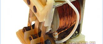
The energy node ensures the formation of an electromagnetic field sufficient to obtain a certain unidirectional force. This field appears as a consequence of the flow of electric current through a coil with a core. Its shape is either U- or W-shaped, depending on the design of this switching product.
The magnetic field lines are most concentrated near the core, and therefore the power unit is designed so that the impact on it from the energy unit is maximized. For a more uniform force that occurs when alternating current flows through the coil, a short-circuited turn is made in it. It plays the role of a damper that prevents contact chatter at a frequency of 50 Hz. If the coil is powered by direct current, a dielectric spacer is placed on its core to prevent magnetized parts from sticking together.
The power unit contains a movable spring-loaded ferromagnetic element - an armature, which is attracted to the stationary coil core, transmitting force to the switching unit. It contains contacts. Their number may vary, depending on the design of the contactor. To control electric motors in three-phase networks, there are three or four contacts - identical in their characteristics. But there may also be additional low-power contacts used to control auxiliary elements of the circuit.
- The location of additional contacts determines the difference between a contactor and a magnetic starter. They are located in a group with the main contacts, and not on the side, as in a magnetic starter.
In addition to the contacts, the switching block contains chambers for extinguishing the electric arc.
How to choose a switch location
Before you begin installing the switch, you should decide on its location. It is necessary to weigh all the pros and cons of its location. The most common location of switches is near the door. This is convenient when you can control the light in the entire room when leaving or entering. Other options are also possible. For example, switches are located at the head of the bed.
Before you begin installing the switch, you need to understand its connection diagram. Regulatory regulations for installation should be taken into account: the switch cannot be located closer than sixty cm from the shower stall and at least half a meter from the gas branch.
According to them, you also need to step back about 10 cm from the doors and almost a meter from the floor. In rooms with high humidity and large temperature changes, you should avoid installing switches.
How does it work
The power unit spring keeps the contacts open. When the force from the armature becomes sufficient to overcome the elastic forces of the spring, the power and switching units begin to move. The anchor deforms the spring, simultaneously dragging the contacts along with it, and they close. The armature is in contact with the core of the coil and is held by its electromagnetic field. After de-energizing the coil, the spring returns to its original state along with the armature and contacts.
For normal operation of the contactor, a voltage of a strictly defined value is supplied to the terminals of its coil. For contactors used in electrical networks, these are 220 and 380 V. Therefore, it is necessary to correctly connect the coil to a three-phase network. If the rated voltage of the contactor is 220 V, the coil is connected to any of the phases (to phase voltage). And if 380 V - between any two phases (to line voltage).
A push-button station is used to control the contactor. It consists of two buttons:
- normally open for switching on;
- normally closed to turn off.
The contactor connection diagram combines an additional contact and a push-button station. The button designed to turn on and the additional contact are connected in parallel, and through them voltage is supplied to the coil. Pressing the power button closes the coil circuit. The anchor moves and closes all contacts. The additional contact makes the power button unnecessary to power the coil. Therefore, after the contactor has tripped, it can be released.
The state of the contactor will not change. It will remain on. But the contacts of the shutdown button are closed until the button is pressed. We press on it - the coil's power circuit is broken. The magnetic field disappears, and the contacts open under the influence of the contactor spring. The coil's power supply circuit is also broken at an additional contact. Therefore, the shutdown button can be released, and this will not affect the state of the contactor in any way.
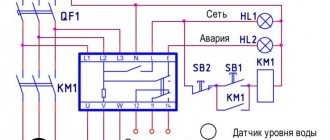
ATS circuit for 2 starters
The second scheme is a little more complicated. It already uses two magnetic starters.
Let's say you have two three-phase inputs and one consumer. The circuit uses magnetic starters with 4 contacts:
3 normally open
1 normally closed KM1
The starter coil KM1 is connected through phase L3 from the first input and through the normally closed contact KM2. So when you apply power to input #1, the coil of the first starter is closed and the entire load is connected to voltage source #1.
The second contactor is turned off, since the normally closed connector KM1 will be open at this moment, and power will not be supplied to the coil of the second starter. When the voltage disappears at the first input, contactor-1 disappears and contactor-2 turns on. The consumer remains with the light.
The main advantage of these schemes is their simplicity. The downside is that such assemblies can be called automation schemes with a very big stretch.
As soon as the voltage disappears in the phase that powers the switching coil, you can easily get a counter short circuit.
You can, of course, improve the entire system by choosing a contactor coil not for 220V, but for 380V. In this case, control will be carried out in two phases.
But you still won’t protect yourself 100%. And if you take into account the moment of possible sticking of contacts, then even more so.
In addition, you will not be protected in any way from too low voltage. Starter No. 1 can turn off only if U at the input is below 110V. In all other cases, your equipment will continue to receive low-quality electricity, although it would seem that there is a second serviceable input nearby.
To increase reliability, you will have to complicate the circuit and include additional elements in it:
voltage relay
phase control relay, etc.
Therefore, recently, to assemble ATS circuits, special relays or controllers—the “brains” of the entire device—have increasingly begun to be used. They can be from different manufacturers and perform the function of not only turning on backup power from one source.
Suddenly you are faced with a more difficult task. For example, it is necessary for the circuit to control two inputs at once and, in addition, a generator. Moreover, the generator should start automatically.
The working algorithm here is as follows:
1.If input No. 1 is faulty, automatic switching to input No. 2 occurs. 2. If there is no voltage at both inputs, the generator starts and the entire load is switched to it.
Features of the circuits
From the illustrations showing how the contactor is constructed, it is obvious that it does not have any protection. But it is unacceptable to operate circuits that do not have at least fuses. Especially in the presence of unwelded and unsoldered connections of wires and cables. In connections made using hardware, when the contacts are loosened, the contact resistance increases like an avalanche. And, as a consequence of this, heating of the current-carrying conductor, melting of the insulation, short circuit and, possibly, ignition of something.
Such contact deterioration can occur in any electrical product in which the wire is pressed with a screw. If this product is a circuit breaker that has thermal protection, it will trip due to heat in the frame. However, a contactor or magnetic starter does not have such protection. Therefore, regular periodic inspection and fuses are the only countermeasures against such malfunctions.
Subtleties of connecting a 220 V device
Regardless of how it is decided to connect the magnetic starter, the project must have two circuits - power and signal. Voltage is supplied through the first, and the operation of the equipment is controlled through the second.
Features of the power circuit
Power for the MP is connected through contacts, usually designated by the symbols A1 and A2. They receive a voltage of 220 V, if the coil itself is designed for such voltage.
It is more convenient to connect the “phase” to A2, although there is no fundamental difference in the connection. The power source is connected to the contacts located lower on the housing.
The type of voltage does not matter, the main thing is that the rating does not go beyond 220 V.
Through a magnetic starter equipped with a 220 V coil, it is possible to supply voltage from a diesel and wind generator, battery, and other sources. It is removed from terminals T1, T2, T3
The disadvantage of this connection option is that to turn it on or off you need to manipulate the plug. The circuit can be improved by installing an automatic machine in front of the MP. It is used to turn the power on and off.
Changing the control circuit
These changes do not affect the power circuit; in this case, only the control circuit is upgraded. The whole scheme as a whole undergoes minor changes.
When the keys are in the same casing, the assembly is called a “button station.” Each of them has a pair of inputs and a pair of outputs. The “Start” button has normally open (NC) terminals, while the one directly opposite has normally closed (NC) terminals.
The keys are built in series in front of the MP. The first one is “Start”, followed by “Stop”. The contacts of the magnetic starter are manipulated by means of a control pulse.
Its source is the pressed start button, which opens the path for supplying voltage to the control coil. “Start” does not have to be kept on.
It is supported by the principle of self-capture. It consists in the fact that additional self-locking contacts are connected in parallel to the “Start” button. They supply voltage to the coil.
After they are closed, the coil is self-energized. A break in this circuit results in the MP being turned off.
The stop button is usually red. The start button can have not only the inscription “Start”, but also “Forward” and “Back”. Most often it is green, although it can also be black.
Connection to 3-phase network
It is possible to connect 3-phase power through an MP coil operating from 220 V. Typically, the circuit is used with an asynchronous motor. The signal circuit does not change.
One phase and “zero” are connected to the corresponding contacts. The phase conductor is laid through the start and switch off keys. A jumper is placed on contacts NO13, NO14 between the closed and open contacts
The power circuit has differences, but not very significant. Three phases are supplied to the inputs indicated on the plan as L1, L2, L3. The three-phase load is connected to T1, T2, T3.
Input into the thermal relay circuit
In the gap between the magnetic starter and the asynchronous electric motor, a thermal relay is connected in series. The choice is made depending on the type of motor.
The thermal relay will protect the electric motor from malfunctions and emergency situations that may arise when one of the phases fails
Connect the relay to the terminal with the magnetic starter. The current in it passes to the motor in series, simultaneously heating the relay. The top of the relay is equipped with additional contacts integrated with the coil.
Relay heaters are designed to accommodate the maximum amount of current flowing through them. They do this so that when the engine is in danger due to overheating, the relay can turn off the starter.
Re: Connecting a motor without a starter
With frequent switching on and off of a loaded machine, premature wear of the power contacts is possible. Carbon deposits form on it, which increases the contact resistance and, as a result, heats up. Starters, by the way, can also sin with this. Older people should remember Soviet times, when electricians on duty at production often had to change contacts on starters due to burnt contacts - fortunately they were replaceable and replaceable within the limits of their size.
Acshel Posts: 46 Joined: 02 Feb 2016, 18:32
Re: Connecting a motor without a starter
By itself! - PML, PME, PMA if I'm not confusing anything. Although in fact it wasn’t that long ago, and they’re probably still changing it here and there...)
Vadim84 Messages: 61 Registered: Jan 19, 2016, 5:59 pm
additional information
There is no fundamental difference between a contactor and a magnetic starter, and this has already been mentioned above. Their task is also the same - remotely turning on and off the load. The circuits in which these types of switches are used are also identical. When describing circuits, some specific terms are used. We will dwell on them further for completeness of information.
"Self-pickup." This means that the power button in the push-button station is connected in parallel with a contact that is closed by the action of the coil, the power of which begins immediately when the said button is pressed. Self-retaining, although not mentioned earlier, is present in each of the schemes shown above.
"Reverse". The reverse circuit involves obtaining from two contactors or magnetic starters the switching of the motor windings to change the rotation of its rotor to the opposite. An example of such a scheme is given below.
Connection diagram for abb esb 20-20 contactor via switch
A contactor, which is controlled by a switch, is used to turn energy-consuming equipment on and off. The most obvious example of how such a combination works is the system for turning on and off all the lights in an apartment from one place.
Such a main switch is usually installed at the exit from the apartment. When leaving home, you can use it to turn off all the lights at once. The reverse procedure awaits you when you return; by pressing the switch key, you turn on all the lights that were working before leaving.
To implement this logic of lighting operation, you will need a contactor and a switch. ABB ESB 20-20 modular contactor , paired with a conventional single-key light switch.
Before we look at the connection diagram in detail, a few words about this contactor model.
Each symbol in the name of ABB contactors has a specific meaning.
Typically the marking looks like this:
ABB series xx-yz
Amperage voltage , where
ABB is the name of the manufacturer
series – Equipment series XX – current for which the contacts are designed Y – Number of contacts to be closed (normally open/open NO) Z – Number of contacts to be opened (normally closed/closed NC)
amperage – Rated current, voltage – Operating voltage
We talked in detail about how a contactor is designated on single-line diagrams HERE.
The ABB 20-20 modular contactor we selected:
– belongs to the ESB series, considered “household”;
– The rated current for which the contacts are designed is 20A;
– contains 2 independent closed contacts, which, until a signal is received, are normally open;
This logic of contactor operation (normally open contacts) when controlling a switch is most preferable in most cases and allows you to operate a load of up to 40A (2 pairs of contacts of 20A each).
It is more convenient to use a modular contactor with a 220V AC coil (the coil voltage is indicated on the device body, in our case it is 250 Volts “
Using three-switch circuits
Article rating:. The switching mechanism in pass-through switches is located in the center of the contacts.
The device provides comfortable light control and safe movement of people. With such a power supply arrangement, identical devices will not work. The more devices are involved in the implementation of the control system, the more complex the construction scheme becomes.
Useful video Switch from three places - a modern solution for light control Electricity and other resources are rising in price, and the emergence of modern technologies allows for significant savings.
Many novice, non-professional electricians confuse these concepts and try to organize a pass-through circuit on a three-key switch. Take a screwdriver with a phase detector or a multimeter, and look for where the plus is and where the minus is. We are talking about long corridors, stairs, basements.
Let's say one of them will be located near the bed, the second at the exit of the room, and the third near the desktop. The appearance of the duplicating devices is almost the same as that of a single-key device. Three-key pass-through switch Such a switch is not actually a pass-through switch, and cannot be used in a lighting circuit with several switching points. If you need a diagram for connecting a pass-through switch from two places, see it in this article.
During installation, the switches are installed so that when turned off the keys are in the same direction. It contains both an input and an output in the amount of 2. Meanwhile, the cross switch has a completely different circuit and switching mechanism. According to the wiring rules, all wires in such an electrical circuit must be located at a distance of 15 cm from the ceiling. The lighting device is turned on when 2 switches are in the same position.
Similar fastening of the remaining outputs. And the other two are installed on some courtyard buildings, a garage, a shed, upon reaching which you can turn off the lighting. In everyday life, not only step-down transformers are used, but also step-up transformers. The apartment buildings have three floors.
Let's say one of them will be located near the bed, the second at the exit of the room, and the third near the desktop. Connecting a line to a wire with the wrong cross-section. Pass-through switches from 5 places without junction boxes. tokzamer.ru
Connection diagram for ABB esb 20-20 contactor for 220V via a switch
Below is a visual diagram of the operation of a contactor through a switch.
It is assembled as follows:
“Phase” is supplied to the switch, which, having passed through it, returns to the control terminal A2 of the contactor. “Zero” is permanently connected to the second terminal A1. A phase is also connected to terminal 1 of the contactor, and a conductor going to the load is connected to terminal 2.
The principle of operation is simple: as soon as you press the switch key, electric current flows to the contactor terminal A1, and therefore to the coil. Next, according to the principle of an electromagnet, the internal contacts, which are normally open, are closed, and the electric current flows to consumers - electrical equipment. As soon as you click the switch key again, the electrical circuit is broken and the contacts inside the modular contactor open, de-energizing the equipment. It's quite simple.
To the second terminals 3-4, you can connect another load up to 20A, for example, a second group of lamps. Accordingly, in total, the contactor will withstand about 9 kW (current - 40A) power.
If you assemble a similar circuit without using a contactor , simply passing the phase of the common power cable of all lighting groups through a switch, problems immediately arise:
– You are limited by the maximum current that the switch can withstand, rarely more than 10A.
– Since the switch does not have any contact protection systems, it would quickly fail, the contact pads would burn out or the housing would melt. A fire may occur.
As you can see, there is nothing complicated about connecting a contactor through a switch. And now, understanding the logic of operation and the order of connection, you will be able to independently develop and implement interesting, and most importantly useful equipment control schemes using contactors.
Contact system on the contactor
Regardless of the standard size and manufacturer of electrical equipment, any three-phase contactor has a standard diagram of contacts and their connections. For ease of installation, all contacts are marked indicating their purpose. The marking is applied to the body of the device and looks like this:
- A1 (zero) and A2 (phase) – contacts for controlling the switching on and off of the contactor;
- Odd numbers 1, 3, 5 and markings L1, L2, L3 indicate the three-phase power input locations;
- Even numbers 2, 4, 6 and markings T1, T2, T3 indicate the connection points of the wires going to the current consumer;
- 13NO and 14NO are a pair of block contacts to provide the self-latching function.
Contact A2 is duplicated in the upper and lower parts of the device body for ease of switching. For the same purpose, the upper and lower (odd and even) group of power contacts can also be used to input or output power. When installing the contactor, you must be careful, otherwise the circuit will not work.
Incorrect phase connections must not be allowed. If you mix them up when installing the contactor, you will get reverse rotation of the motor. For this purpose, there are two ways of marking the insulation of cable cores - with numbers and color. The colors 1, 2 and 3 are yellow, green and red. The neutral conductor is white or marked with the number “0”. Connecting power contacts is not difficult. The main thing is the correct connection of the control voltage through the push-button station.
What is a modular contactor and what is it for?
According to its functional purpose, the modular contactor KM belongs to the switching equipment for remote control of powerful loads operating at direct or alternating current. They break current circuits in several places at once, and this differs from electromagnetic relays, which break the circuit at only one point.
Quite often, modular contactors work in conjunction with auxiliary devices - set-top boxes, thermal relays, blocking devices and other modular devices. As a result of such combinations, equipment is obtained that has special properties and is capable of performing specified functions. So, when installing a delay module, you get a contactor with a delay function, and a thermal overload relay transfers the contactor to the category of a magnetic starter.
With the help of auxiliary elements, the capabilities of the main devices are significantly expanded, their performance characteristics are improved, and installation is simplified.
At their core, contactor devices are considered modified versions of a starter, which additionally contains a thermal relay and a contact group for starting the electric motor. Low voltage electromagnetic starters, reversible and non-reversible. The first option includes two identical contactors, with the same rated current. It has a mechanical or electrical interlock that prevents the main contacts from closing at the same time.
The protective functions in these devices are performed by electrothermal current relays and other similar devices. Low power electrical contactor, used as an intermediate relay. It is designed for low-current circuits and has a large number of switchings. Using this device, it is possible to connect many additional sections and control their on/off.
Circuit breaker
The main controller for electricity consumed in a modern apartment is a circuit breaker or simply a “machine”. On the electrical diagram it is located at the very beginning of the circuit, but physically it is usually located next to the electric meter.
Depending on the current strength for which the machine is designed, the maximum permissible power of all connected electrical appliances is set. For example, if the rated current load of the machine is 20 A, then the power of all connected electrical appliances should not exceed 20A x 220V = 4.4 kW. If you simultaneously turn on devices with a total power of 5 kW, then after some time the machine will turn off the power supply. On the one hand, it can be annoying when, simultaneously with a click, the light suddenly goes out and all electrical appliances stop working. But on the other hand, this is a guarantee of fire safety. By turning off the power supply, the machine simply did its job and protected us from major trouble.
To ensure that annoying outages do not occur and safety is maintained, you need to ensure in your apartment such energy consumption conditions under which the rated current of the machine, the power of electrical appliances and the cross-section of the conductors in the electrical wiring correspond to each other. By the way, the required cross-section of wires also depends on the material of the electrical wiring cores. Copper strands can be thinner than aluminum strands because copper has lower electrical resistance and is a better conductor of current.
If the circuit breaker turns off the voltage supply when the permissible power consumption is exceeded, this is a fairly common, one might say, normal situation. But besides this, emergency situations also happen. For example, a short circuit or current leakage controlled by an RCD. In this case, the machine turns off the voltage supply instantly. If this does not happen, the wiring will begin to melt and there will be a fire hazard.
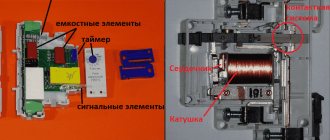
Design and principle of operation
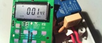
A standard contactor design includes several basic parts. The device consists of a housing (1), a control coil output terminal (2), a power contact terminal (3), a fixed magnetic core (4), a moving part - a core (5), a control coil (6), a short-circuited magnetic circuit ring (7), fixed and moving contacts (8 and 9), on-off indicator lever (10).
The coil is the main element that creates the magnetic current. If it is also used as a throttle, then with its help a driving force is generated that ensures the operation of the devices. The tension of the contacts is fixed using a contact spring. During docking, the moving and fixed contacts are connected to each other. They are constantly in motion and perform certain actions. Fixed contacts are fixed to the body, and movable contacts are connected to the core.
The contactor works as follows:
- After applying voltage to the control coil, the armature is attracted to the core. As a result, the contact group closes or opens, in accordance with the initial position of a particular contact.
- After turning off the power, all actions occur in the reverse order. The electric arc that occurs at the moment of opening is extinguished using an arc extinguishing system.
- After the voltage supply is stopped, the electromagnetic field disappears and ceases to hold the armature or core.
- The return spring moves the contacts to their original position, completely opening the circuit. Thus, the modular contactor performs its main work during periods of supply and shutdown of voltage.
Connecting a magnetic starter via a push-button post
This circuit includes additional start and stop buttons. Both “Stop” buttons are connected in the control circuit in series, and the “Start” buttons are connected in parallel. This connection allows switching with buttons from any position.
Here's another option. The circuit consists of a two-button post “Start” and “Stop” with two pairs of contacts, normally closed and open. Magnetic starter with a control coil for 220 V. The power supply for the buttons is taken from the terminal of the power contacts of the starter, number 1. The voltage approaches the “Stop” button, number 2. It passes through a normally closed contact, along the jumper to the “Start” button, number 3.
We press the “Start” button, the normally open contact number 4 closes. The voltage reaches the target, number 5, the coil is triggered, the core is retracted under the influence of the electromagnet and sets in motion the power and auxiliary contacts highlighted in dotted lines.
The auxiliary block contact 6 bypasses the contact of the “start” button 4, so that when the “Start” button is released, the starter does not turn off. The starter is turned off by pressing the “Stop” button, number 7, the voltage is removed from the control coil and the starter is turned off under the influence of the return springs.
Classification of contactor devices
There are different types of contactors, differing from each other in various respects. Among them, the following parameters can be distinguished.
First of all, they are classified according to their purpose. This includes the following types and categories:
- Devices for remote switching. Most of them operate under manual operator control using buttons or switches. At the right time, a signal is given and the device is activated. In another method, several contactors are connected into a common automated power system that uses electronic circuitry to issue commands. In case of an emergency, a protection system is provided that opens the contacts.
- Switching on powerful electrical equipment using low-current lines. The question arises, why is a contactor needed in such cases? Wouldn't it be better to use a traditional button? This, of course, can be done, but then you will need very massive and bulky equipment, and the switching process itself will require significant effort. The same goes for turning it off. Therefore, compact low-current devices are used for these purposes, allowing for high-frequency on-off cycles. Thus, a weak current is supplied to the coil, and only then the powerful electric motor is started.
Hallway and corridor
Several scenarios can be implemented in the hallway and corridor. The following combination is recommended as the main one: the main overhead light, dim wall lighting with adjustable direction of the light flow (for paintings and other artistic creations) and something local that allows you to illuminate a separate object well, without contrasts, for example, a full-length mirror . It would also be useful to have a low-power lamp on the table so that you can avoid turning on the overhead light when quietly leaving or arriving early in the morning or at night.
In a long corridor, the “take-off” is very ergonomic - low-lighting at night, which allows you to conveniently visit the toilet or look into the refrigerator if someone is prone to waking up at night due to a suddenly inflamed appetite. It will be even more convenient if the take-off is controlled by a motion sensor that turns on the light when a person appears and turns it off a few minutes after he disappears. The main advantage of such lighting is comfort for eyes that are not accustomed to bright light after sleep.
A noteworthy idea is an additional one or more outlets in the hallway for electronic gadgets - NAS, Wi-Fi router, etc. An Ethernet cable for the TV will also be in place.
Connection diagrams for consumers and modular contactors
In accordance with the type of electrical equipment used, in each case an individual connection diagram for the modular contactor is provided. The most widespread is the standard version, which uses only one device, as well as reversible circuits and with the connection of single-phase consumers. Each of them should be considered in more detail.
The most popular scheme is connecting a three-phase electric motor through a modular contactor KM (Fig. 1). The usual START and STOP buttons are used for control. Overload protection is provided using a thermal relay. In case of short circuits, the electrical circuit is equipped with an automatic switch.
Another circuit is reversible (Fig. 2), used when connecting a modular contactor to an electric motor so that the reverse function appears. It is constantly needed in various lifting mechanisms, machines and other equipment. In this case, another switching device is connected. It is involved in changing the locations of two phases, which also leads to a change in the direction of rotation of the shaft. This circuit is also supplemented with protective equipment - a thermal relay and a circuit breaker.
The main purpose of contactors in the third circuit is to work with single-phase consumers. As a rule, these are lighting systems, electric pumps and other equipment operating with a single phase.
Turning on/off a 380 V asynchronous motor
Despite the fact that the motor is 3-phase (380V), a 220 V coil is used. The difference between this circuit is that the power contacts switch 3 phases (380 V), and the magnetic starter is controlled using 1 phase (220 V ). Phases A, B, C are connected to contacts L1, L2, L3, and the electric motor is connected to contacts T1, T2, T3. The control voltage is supplied to contacts A1 and A2, and one of these contacts is supplied with one of the phases, for example phase B, although any phases can be connected. The second contact is connected to the neutral wire. A block contact (BC) is also connected, ensuring the operation of the equipment after the “Start” button is released.
Connecting a three-phase motor via a starter
The circuit has been slightly modified due to the addition of a thermal relay that protects the electric motor from overloads, as well as a QF circuit breaker that protects the circuit from short circuits.
The connection procedure is presented in the following video.
How to connect a three-phase motor through a magnetic starter.
Watch this video on YouTube