Global trends - the demand for reducing CO2 emissions, increasing the intensity of energy conservation - lead to the need for balanced energy consumption, for which electronic process control circuits can be of great help. The most common cases are optimizing battery performance, controlling motor speed and transients in servers, and managing solar panels. It is important for operators of such systems, in particular, to know how much current flows in the circuit. Current sensors can provide invaluable assistance in this regard.
Let's measure the current and tell you how much
A current control relay (RCT) is an electrical device built on the principle of measuring the load current of an electrical network and outputs control signals when the measured value reaches threshold values, both upward and downward.
In other words, a current control relay is a modular device designed to monitor the amount of current consumed by the load so that, at the slightest deviation from the set values, it instantly sends a special signal to turn off and prevent overloads of electrical equipment.
DIY current sensor
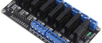
If for some reason it is impossible to purchase a standard sensor (the best known designs are from the Arduino brand), you can make the device yourself.
Arduino current sensor. The arrow indicates the USB connector.
Required components:
- Op amp LM741, or any other that could act as a voltage comparator.
- Resistor 1 kOhm.
- Resistor 470 Ohm.
- Light-emitting diode.
A general view of the assembled device, made by yourself, is shown in the following figure. This circuit uses the Hall effect, when the control potential difference can change when the location of the conductor in the electromagnetic field changes.
Areas of use
RKT is used in various electrical installations to control the load of electrical equipment. It can signal or give impulses to shut down overloaded installations in networks with limited energy consumption. Or inform the duty personnel about an excessive load reduction, which may be a consequence of an emergency shutdown of equipment, broken power line wires or phases of electrical cables.
Depending on the tasks, the current control relay can be triggered by overvoltage or undervoltage in the electrical network. For this purpose, a special switch for these parameters is provided. The measuring cycle of the current control relay is quite short, so the device quickly responds to changes in its level.
Why are current sensors needed?
Sensors are blocks whose task is to measure a certain parameter, and then, after comparing it with a reference value for a given technical system, send a corresponding signal to the actuator element of the circuit. Since most systems use electric motors, the most common types are current and voltage sensors (an overview of the latter is shown in the following figure).
The widespread introduction of such devices is due to the development of touch control methods, when the original signal - electrical or optical - is converted into the necessary control parameters.
Compared to other control technologies (e.g. contactor control), sensors provide the following advantages:
- Compactness.
- Safety in use.
- High accuracy.
- Environmentally friendly.
Small size and weight often allow the production of multifunctional sensors, such as those that can monitor multiple circuit parameters. These are modern current and voltage sensors.
These detectors include:
- Contact entry groups;
- Output contact groups;
- Shunt resistor;
- Signal amplifier;
- Carrier board;
- Power unit.
The idea that devices can be connected to an existing network does not stand the test of time, because often in extreme situations (fire, explosion, earthquake) it is the built-in power supply systems that are the first to fail.
Detectors are divided into active and passive. The former not only transmit the final signal to the control element, but also control its action.
RKT device and principles of operation
Like all other electrical devices, RKT can be electromechanical and electronic, alternating and direct current. To measure current, the relay must either be embedded directly into the controlled network or connected to it through an instrument current transformer (CT). Low-current relays are connected to the measuring circuit using measuring shunts. In order not to introduce errors into the measured network and reduce losses, the resistance of the embedded shunt should be as small as possible.
In electromechanical relays, the relay current coil is connected to the shunt, and in electronic relays the measuring circuit is based on microprocessors. When the current reaches the relay activation threshold (during overloads), the armature of the electromagnetic relay is pulled up, or the threshold element of the electronic key is triggered, producing a signal. When the current decreases, the electromechanical relay releases the pulled-up armature, causing the contacts to close.
An electronic relay works the same way. Relays with current transformers do not require insertion into the measuring circuit. The primary winding of the CT is the phase wire itself of the circuit being measured. A relay coil or measuring circuit is connected to the secondary winding of the CT. Usually the current transformer is built into the relay itself and the phase wire is passed through a window in its body. RKT can be equipped with time delay settings for operation, a time delay (0.5 - 5 sec) for tuning out the inrush current of electric motors and the magnetizing current of power transformers. The relay returns to its original state when the current returns to its normal value, or remains in the actuated state until action is taken by the personnel on duty (relay with memory). Electromechanical relays have hysteresis, i.e. The operating current is not equal to the release current, but is less than it by about 5%. In other words, the relay return coefficient (Ioperation/Irelease) is 0.95.
Three ways to control the load using monitoring relays:
Current control
Monitoring the current in the motor power supply circuit does not provide a complete picture of the load and can only be used to a limited extent for these purposes, due to the following factors:
- In AC networks, the measured current is the sum of the reactive and active components. When generating mechanical force, it is the active component that is decisive. The reactive component mainly goes to losses and does not affect the torque.
- In an underload situation, the current decreases nonlinearly with respect to the load, but remains relatively high due to the significant influence of magnetizing currents. Therefore, there is no sufficient correlation between the current flow and the load.
- The current depends on the supply voltage. In a voltage drop situation with a constant load, the current will increase. Which makes monitoring the active component difficult.
Therefore, current monitoring allows you to determine only critical conditions in the operation of equipment, such as drive blocking, since in this case the current increases significantly.
Power factor control
Power factor (cos φ) is the cosine of the phase shift angle between the flowing current and the applied voltage. In cases with an electric motor, the cosine phi depends on the load and is theoretically equal to 1 for an ideal situation. However, due to induction, in a real situation the operating value is between 0.85 ... 0.95 at rated load.
In an underload situation, cos φ monitoring allows for timely detection of this condition, since losses increase significantly when the load drops and can reach <0.5 for a no-load engine operating situation.
This control method cannot be used if the installation constantly operates in underload or overload mode (i.e. if the pump or motor is incorrectly selected for this installation), since in this case the load change will have a slight effect on the phase shift angle φ.
Active power control
Monitoring the value of active power allows you to most fully judge the condition of the electric motor, because the effective power is proportional to the power on the shaft. There is a direct correlation between effective power input and engine load (constant speed torque) throughout the entire operating range. Due to the linear characteristic, this control method is the most accurate and informative.
Advantages of load control relays compared to sensors:
- there are no difficulties associated with contamination of sensors and their calibration;
- no maintenance or cleaning required;
- reduction in installation costs, since cable laying is not required;
- no need to use explosion-proof barriers;
- fewer components - higher reliability;
- ease of modernization, since you can use the free space in the existing electrical panel.
Types of RKT and their technical data
RKT are divided into devices:
- AC and DC;
- voltage 12, 24, 36, 48, 220, 400, 660V;
- the strength of the measured current is from several amperes to hundreds of amperes (in a relay with a CT);
- with time delays from 0 to tens of seconds;
- single-phase and three-phase;
- relay protection degree 1P20/1P40 (to ensure personnel safety).
RCTs are mounted on distribution boards, lighting panels, electrical control panels on a DIN rail or on a flat surface. All switches for selecting relay modes (operating current and time delay settings) are located on the front panel of the device. Switching on and off the load is carried out either by the contacts of the relay itself, or with the help of switching devices that provide switching of high currents. RCTs are produced both by domestic industry:
- RKT-1 AS100-265V (single-phase, alternating current from 100 to 26 V);
- RKT-1 AS400V (same for 400V);
- RKT-1 DC24V (24V DC).
Likewise with foreign companies:
- CM-EFS/25 (AC and DC from 3 to 660V, ABB company).
Classification and connection diagrams
Current sensors are designed to evaluate the parameters of direct and/or alternating current. The comparison is performed using two methods. In the first case, Ohm's law is used. By setting the shunt resistor according to the system load, a voltage is created across it that is proportional to the system load. The shunt voltage can be measured by differential amplifiers, such as current shunt, operational, or difference amplifiers. Such devices are used for loads that do not exceed 100 A.
AC current measurement is performed in accordance with Ampere's and Faraday's laws. When a loop is placed around a current-carrying conductor, a voltage is induced there. This measurement method is used for loads from 100 A to 1000 A.
The diagram of the described measurements is presented in the figure:
On the left - measurement of small currents; on the right - measurement of high currents
The measurement is usually made at a low input common mode voltage. Using a sensing resistor, the current sensor is connected between the load and ground. This is necessary because common mode voltage always takes into account the presence of op amps. The load provides power to the device, and the output resistance is grounded. The disadvantages of this method are the presence of interference associated with the system load potential to ground, as well as the inability to detect short circuits.
To monitor the operation of powerful systems, the detector is connected to an amplifier between the power source and the load. As a result, the values of the parameters supplied by the power supply are directly monitored. This allows possible short circuits to be identified. The peculiarity of the connection is that the common-mode voltage range at the amplifier input must correspond to the load supply voltage. Before measuring the output signal of the device being monitored, the load is grounded.
Some manufacturers
- ABC;
- iemens;
- Legrand;
- EKM (Russia);
- Meander (Russia).
For detailed information on the service “Assembly of switchgear switchboards”, please contact our office by phone
Payment methods for completing and assembling electrical panels:
For the convenience of our Customers, payment for the completion and assembly of electrical panels can be made in the following ways:
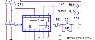
An example of setting up a power factor control relay to protect a pump from “dry running”
The situation of “dry running” of the pump leads to a significant drop in the power factor, therefore, to protect the pump, it is necessary to set the control function to decrease (U) and set the threshold value for operation of the cos φ min regulator. If the power factor in the pump power supply circuit drops below a preset threshold value, the relay will open.
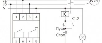
The device's own supply voltage supplied to terminals A1-A2 is determined by the power supply module, for example TR2-230VAC and TR2-400VAC respectively for the connection diagrams below.
Connection diagram for monitoring a 1-phase load powered by a 230V AC measurement circuit, direct current measurement (up to 10 A)
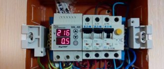
Connection diagram for monitoring a 3-phase load powered by a 400V AC measuring circuit, with current measurement via a current transformer xxx/5A
Technik braucht Kontrolle . Since 1963, TELE has been developing and manufacturing industrial automation devices. Headquartered and production in Vienna, Austria, more than 60 distributors worldwide and one of the largest lines of relay automation devices.
Constant control
Constant monitoring of power networks for the presence of ground leakage currents (or zero-sequence currents) improves the operational availability and performance of power systems and eliminates the possibility of emergency situations. Such monitoring also makes it possible to obtain information about the real state of the power supply network. RCM-A and RCM-B series products (RCM = residual current monitor) from Phoenix Contact are residual current monitors according to DIN EN 62020 (VDE 0663) that fully satisfy these requirements and are available in the following versions:
1) Type A for detecting AC leakage current and pulsating DC leakage current;
2) Universal type B, capable of detecting all types of leakage currents: alternating, pulsating direct, “pure” direct to ground. Residual current monitoring devices detect insulation faults at an early stage (Fig. 1).
Rice. 1. Shutdown of the power system due to insulation breakdowns leading to leakage currents to the ground
The control results are constantly monitored and an alarm is generated when preset limits are reached. By receiving this information in advance, the operating company can correct the problem before the system is forced to shut down. Damage can be easily tracked and repaired outside of business hours. This significantly increases the availability of power systems.
Introduction
Today, electric motors are used in all industries. In this case, as is known, the current consumption of the electric motor depends on the nature of the load.
Prime examples of technological processes where measuring motor current is very important are:
- grinding of solid product (crushing);
- maintaining consistency (mixing);
- extrusion using a screw press.
This article will discuss the main problems that arise when automating such processes and various ways to solve them.
Unscheduled downtime
Today, the security of power systems has reached a fairly high level, which is not least the result of the application of a wide range of standards. This high level of safety is partially achieved with the help of protective elements: circuit breakers and differential current protection devices, automatic differential switches (difavtomat), which in the event of a breakdown promptly isolate individual loads or entire circuits. However, instant disconnection of the load when the differential current protection device reacts to a high differential current of a given value is not always desirable from the point of view of equipment operability, since the disconnection is carried out without prior notification. As a result, the operating company is deprived of the opportunity to carry out preventive measures.
High discharge currents, harmonics and electromagnetic fields are additional factors that negatively affect the performance of power systems. Designers, installers and operators are therefore faced with the challenge of identifying such effects early and eliminating them with a suitable protection scheme that will ensure safe operation. Indirectly, some of these negative effects are eliminated by choosing a TN-S type grounding system at the design stage - a network configuration with separate protective and working zeros (N and PE).
Although the incidence of high pulsed discharge currents, noise and electromagnetic fields can be minimized through proper design, differential leakage currents caused by insulation faults cannot be completely eliminated (even with ideal design). These difficult-to-predict events have a profound impact on the availability of all power systems.
Safety precautions
ATTENTION!
Personnel with technical education and special training (training and knowledge testing) in the safe performance of work in electrical installations with a group of at least 2 for repair personnel, as well as those with experience in equipment maintenance are allowed to carry out installation, adjustment, repair and maintenance of process equipment , in the design of which changes and additions are made, or modernization is carried out. KIP‑Service LLC is not responsible for equipment malfunctions and the safety of workers during unqualified installation and maintenance.