Usually we see this device in the form of a neat box with two buttons: “start” and “stop”. If you remove the top cover, inside you will find a switch of a rather complex design that can perform several tasks (both in turn and simultaneously).
This is an electromagnetic starter. The question arises: why create complex electrical devices if you just need to close two (or more) contacts? There are buttons with fixation, lever switches, circuit breakers, switches. Let's consider a typical application of a magnetic starter: turning on a powerful electrical installation (for example, an asynchronous electric motor).
- A powerful contact group with arc extinguishers is required; accordingly, a lot of force is required to close the contacts. A manual drive will be quite cumbersome (using a classic switch does not always fit into the aesthetics of the workplace).
- It is difficult to quickly change the operating mode with manual switches (for example, changing the direction of rotation of the motor). The magnetic starter device allows you to assemble such a connection diagram.
- Organization of protection. Any machine with an emergency shutdown is not designed to be turned on multiple times. The purpose (albeit not the main one) of a magnetic starter is not only to repeatedly switch, but also to disconnect the power circuit in case of overloads and short circuits. At the same time, it has an undeniable advantage over other switches. The shutdown is irreversible: that is, after an emergency opening of the contacts, or a momentary loss of power, the operating contacts do not return to the default “ON” position. The principle of operation of the magnetic starter implies only forced restart.
Purpose and device
Magnetic starters are built into electrical circuits for remote starting, stopping and providing protection for electrical equipment and electric motors. The operation is based on the use of the principle of electromagnetic induction.
The basis of the design is a thermal relay and a contactor combined into one device. Such a device can also operate in a three-phase network.
Such devices are gradually being replaced from the market by contactors. In terms of their design and technical characteristics, they are no different from starters, and they can only be distinguished by their name.
They differ from each other in the supply voltage of the magnetic coil. It comes in 24, 36, 42, 110, 220, 380 W AC. The devices are produced with a coil for direct current. Their use in an alternating current network is also possible, for which a rectifier is needed.
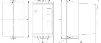
The starter design is usually divided into upper and lower parts. In the upper part there is a movable contact system combined with an arc extinguishing chamber. Also located here is the moving part of the electromagnet, mechanically connected to the power contacts. All this makes up a moving contact circuit.
At the bottom there is a coil, the second half of the electromagnet and a return spring. The return spring returns the upper half to its original state after de-energizing the coil. This is how the starter contacts break.
- Normally closed. The contacts are closed and power is supplied constantly; shutdown occurs only after the starter is triggered.
- Normally open. The contacts are closed and power is supplied while the starter is running.
The second option is the most common.
Design and technical parameters
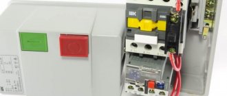
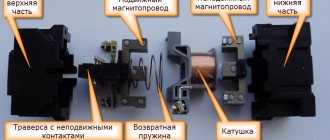
Magnetic starter PM12
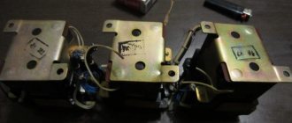
Magnetic starter device:
- Core;
- Electromagnet coil;
- Anchor;
- Polymer frame;
- Mechanical work sensors;
- Central and additional group of contactors.
Magnetic starter disassembled
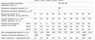
Main parameters displayed in the technical documentation:
- The measure of current passing through the central terminals is the magnitude of currents at which the device is operational over a long period of time with specified parameters;
- The maximum current value that the device can operate;
- The voltage of the connected circuit is the voltage of the operated circuit at which the insulation between the central terminals retains its technical parameters;
- The control voltage of the electric magnet coil is the alternating or constant supply voltage of the electromagnet;
- Relay and electromechanical resistance to wear - the indicator is expressed in the number of cycles for closing and opening the terminals. Relay wear resistance is determined according to the corresponding graph displayed in the accompanying documentation for the device. By substituting the values of the supply voltage and current of the operated network, it is possible to determine the parameter yourself;
- Limit number of operations per unit of time;
- Number of additional terminals and method of their implementation;
- Time period for connection and disconnection.
In addition, the electromagnetic starter can be supplemented with:
- Protective relay to prevent overheating and electrical overloads of the end user;
- Additional set of terminals;
- Starting device for the engine;
- Electrical fuses.
Principle of operation
The principle of operation of a magnetic starter is based on the phenomenon of electromagnetic induction. If no current passes through the coil, then there is no magnetic field in it. This causes the spring to mechanically push away the moving contacts. As soon as the power to the coil is restored, magnetic fluxes appear in it, compressing the spring and attracting the armature to the stationary part of the magnetic circuit.
Since the starter operates only under the influence of electromagnetic induction, the contacts open during power outages and when the network voltage drops by more than 60% of the nominal value. When the voltage is restored again, the contactor does not turn on on its own. To activate it, you will need to press the “Start” button.
If it is necessary to change the direction of rotation of an asynchronous motor, reversing devices are used. Reverse occurs thanks to 2 contactors, activated in turn. When the contactors are turned on simultaneously, a short circuit occurs. To eliminate such situations, the design includes a special lock.
MP with AC coil
If the magnetic starter is equipped with an alternating current coil, then the magnetic flux in its magnetic circuit periodically decreases to zero simultaneously with a decrease in the current in the coil. In this case, the force of attraction of the upper part of the magnetic circuit of the MP to the lower one also decreases to zero, and the return spring slightly lifts it up. Then, as the magnetic flux increases, the upper part is again attracted to the lower. As a result, the MP vibrates. In addition, due to the magnetostriction effect, a hum occurs emanating from the magnetic circuit, similar to what occurs in a transformer.
To prevent these phenomena, a short-circuit is laid at the end of the core of the magnetic circuit of the MP. a copper coil covering approximately a third of its cross-section. When the flux changes inside the coil, an alternating current is also induced in it, creating its own flux, shifted in phase relative to the main one. As a result of the interaction of these two flows, a resulting flow arises that has a constant component, the action of which is sufficient to reliably attract parts of the magnetic circuit to each other during the entire time the MF is turned on.
Varieties and types
Starters manufactured according to Russian standards are divided into 7 groups depending on the rated load. The zero group can withstand a load of 6.3 A, the seventh group - 160 A.
This must be remembered when choosing magnetic starters.
The classification of foreign analogues may differ from that accepted in Russia.
It is necessary to be guided by the type of execution:
- Open. Suitable for installation in closed cabinets or places isolated from dust.
- Closed. Installed separately, in dust-free rooms.
- Dust-splash-proof. Can be installed anywhere, including outdoors. The main condition is the installation of a canopy that protects from sunlight and rain.
By type, the electromagnetic starter can be selected according to the following parameters:
- Standard versions in which voltage is supplied to the starter with further attraction of the core and activation of the contacts. In this case, depending on whether the starter is normally closed or normally open, the electrical equipment is turned on or off.
- Reversible modifications. This device is a reverse with electromagnets. This design allows you to avoid turning on 2 devices at the same time.
The marking of the magnetic starter encodes its technical characteristics. The designation is located on the body and can contain the following meanings:
- Device series.
- Rated current, the designation of which is written in a range of values.
- The presence and design of a thermal relay. There are 7 degrees.
- Degree of protection and control buttons. There are 6 positions in total.
- Availability of additional contacts and their types.
- Compliance of fastenings with standard mounting frames.
- Climate compliance.
- Accommodation options
- Wear resistance.
There are several options for installing magnetic contactors in control systems, starting with the simplest control of electric motors and ending with installation with holding the contact button, or reverse.
Connection diagram for 220 V
Any electrical connection diagram contains 2 circuits, including for a single-phase network. The first is the power one, through which power is supplied. The second is a signal one. With its help, the operation of the device is monitored.
The connected contactor, thermal relay and control buttons form a single device, which is marked as a magnetic starter in the diagram. It ensures the proper functioning and safety of electric motors under various operating conditions.
Contacts for connecting the device's power are located in the upper part of the case. They are designated A1 and A2. So, for a 220 V coil, 220 V voltage is supplied. The order in which “zero” and “phase” are connected does not matter.
Domestic models of popular starters
In the classification of starters, the most popular starters are: PMA, PME, PM 12. About them and how to choose a magnetic starter in the following articles.
©Elesant.ru
Other articles in the section: House electrical installation
- Basic standards for electrical installation work
- Introductory machine. Calculation, selection of an introductory machine for an apartment
- Built-in, overhead and hanging floor panels
- Charging the diesel generator battery
- Paper insulated cables
- Cable metal tray
- How to choose a stylish floor lamp
- How to properly install electrical wiring in a bathhouse
- How to reduce prices for electrical work
- Distribution panel complete set, circuit breakers, connection terminals
Connection diagram for 380 V
The standard circuit is used in cases where it is necessary to start the engine. Control is carried out using the “Start” and “Stop” buttons. Instead of a motor, any load can be connected through magnetic starters.
In the case of power supply from a three-phase network, the power section includes:
- Three-pole circuit breaker.
- Three pairs of power contacts.
- Three-phase asynchronous electric motor.
The control circuit is powered from the first phase. It also includes the “Start” and “Stop” buttons, a coil and an auxiliary contact connected in parallel to the “Start” button.
When you press the “Start” button, the first phase hits the coil. After this, the starter is triggered and all contacts are closed. The voltage passes to the lower power contacts and is supplied to the electric motor through them.
The circuit may differ depending on the nominal voltage of the coil and the voltage of the supply network used.
Stop button
Regardless of the type of electromagnetic starter used in the design, control is carried out using two buttons - “Start” and “Stop”. Reverse may be included. The stop button is different from the others in that it is red. The normally closed contacts are mechanically connected to the button. Therefore, when the devices are operating, current flows through them unhindered.
If the button is not pressed, the metal strip, under the action of a spring, closes two contacts. If you need to stop powering the device, you just need to press the button - the contacts will open. But there is no fixation; as soon as you release the button, the contacts close again.
Therefore, to control the operation of electric motors, special circuits for switching on 220V electromagnetic starters are used. Such devices can be installed on a DIN rail without any problems, so they can be used even in the smallest mounting blocks.
Connection via push-button post
The circuit connecting magnetic starters through a push-button station requires the use of an analog adapter. Contact blocks come with 3 or 4 outputs. When connecting, it is necessary to determine the direction of the cathode. Then the contacts are connected through the switch. To do this, use a two-channel trigger.
If you connect a device with automatic switches, then an electronic regulator is used for them. The blocks may be located on the controller. The most common devices are those with broadband connectors.
Details about electromagnetic starters
Usually we see this device in the form of a neat box with two buttons: “start” and “stop”. If you remove the top cover, inside you will find a switch of a rather complex design that can perform several tasks (both in turn and simultaneously).
This is an electromagnetic starter. The question arises: why create complex electrical devices if you just need to close two (or more) contacts? There are buttons with fixation, lever switches, circuit breakers, switches. Let's consider a typical application of a magnetic starter: turning on a powerful electrical installation (for example, an asynchronous electric motor).
- A powerful contact group with arc extinguishers is required; accordingly, a lot of force is required to close the contacts. A manual drive will be quite cumbersome (using a classic switch does not always fit into the aesthetics of the workplace).
- It is difficult to quickly change the operating mode with manual switches (for example, changing the direction of rotation of the motor). The magnetic starter device allows you to assemble such a connection diagram.
- Organization of protection. Any machine with an emergency shutdown is not designed to be turned on multiple times. The purpose (albeit not the main one) of a magnetic starter is not only to repeatedly switch, but also to disconnect the power circuit in case of overloads and short circuits. At the same time, it has an undeniable advantage over other switches. The shutdown is irreversible: that is, after an emergency opening of the contacts, or a momentary loss of power, the operating contacts do not return to the default “ON” position. The principle of operation of the magnetic starter implies only forced restart.
Design and principle of operation of the device
The main difference between a starter and any other switching device is that the power supply connected to it is also the control one. How it works?
Let's look at the general principle of operation of a magnetic starter using an illustration:
- Power contacts (3), through which high-current power flows to the consumer (electrical installation).
- They are connected to each other using contact bridges (2). The pressing force is provided by springs (1), which are a specially molded steel plate. The contact groups themselves are made of copper alloys for better electrical conductivity.
- The plastic crossbeam (4), on which the bridges (2) are fixed, is connected to a movable anchor (5). The entire structure can be moved vertically using external force (a button), and returns back after the pressure on it is removed.
- Using an electromagnet coil (6), a magnetic field is created that presses the movable armature (5) to the stationary part of the core (7). The force is sufficient to overcome the resistance of the return spring.
- Power is supplied to the electromagnet using additional contacts (8). To ensure proper operation of the circuit, power to these contacts is supplied in parallel to the power ones (3), from a single source. To open the entire contact group, a shutdown button is provided, which is installed in the circuit of additional contacts.
Types of contactors
In terms of equipment with protective equipment: almost all models include a thermal relay unit, which opens the circuit of additional contacts in the event of current overload. In this sense, the operating principle of a magnetic starter is no different from a circuit breaker. After an emergency shutdown and cooling of the protective group (the power circuit of the electromagnet winding is restored), the power contacts do not close. It is assumed that the operator will eliminate the cause of the emergency and restart the electrical installation.
Installation rules
When connecting a magnetic starter, it is important to pay attention to the surface or element to which you plan to attach. Violation of installation rules can lead to false shutdowns in the future, noise effects and other troubles.
In panels, cabinets, and drawers, you must choose a flat, flat surface located in a vertical plane. The installation location must have a reliable, rigid fixation in space. It is prohibited to install electromagnetic starters in places of high heat, subject to impacts, jolts and other mechanical influences.
To reduce the mechanical load from the cable on the contact groups, the conductor must be bent into a ring or U-shape. The same technique is used for additional contacts.
Before commissioning, the structural elements must be inspected for damage. The correct connection, marking and sequence are checked.
Connection diagrams
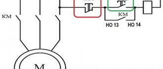
What is a magnetic starter used for? Mainly for organizing the safe connection (and control) of asynchronous three-phase motors. Therefore, we will consider options for the operation of the circuit under various conditions. In all illustrations there is a protective relay indicated by the letter “P”. Bimetallic plates that activate the emergency switch (installed in the control circuit) are located on the power lines of the contact group. They can be placed on one or more phase conductors. If there is overheating (it occurs when the load is exceeded or a simple short circuit), the control line breaks and power is not supplied to the “KM” coil. Accordingly, the power contact groups “KM” open.
Classic circuit for direct connection of a three-phase electric motor
The control circuit uses power from the voltage between two adjacent phase lines. When you press the “Start” button, the “KM” coil circuit is closed using its main contact. In this case, all contact groups, including additional contacts in the control circuit, are connected under the control of the coil electromagnet. There are two ways to open the circuit: when the emergency relay is activated, or by pressing the “Stop” button. In this case, the magnetic starter returns to its original “all off” position (or in the case of two categories of contacts, the normally closed groups will be connected).
The same connection option, only the control circuit is connected to the phase and neutral. From the point of view of starter operation, there is no difference. The buttons and the protective thermal relay work in the same way.
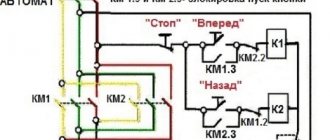
Reversible connection of a three-phase electric motor
As a rule, two electromagnetic starters are used for this, in which the outputs of the phase contacts are combined with a shift. The devices are combined into one switch, so it can be considered as a single element.
Depending on which contact group is connected to the electric motor, its rotor rotates in one direction or the other. This option is indispensable when used on conveyors, machine tools, and other electrical installations that provide 2 directions of rotation (movement).
How does this scheme work in practice? Let's look at the illustration:
A single control scheme with two groups of start buttons: “Forward” and “Back”. Each of them includes a corresponding electromagnet coil. Why is the scheme common? According to safety conditions, the “Stop” button should be uniform. Otherwise, if an emergency occurs, the operator will lose precious seconds searching for the required button (for “Forward” or for “Back”).
Method number two. Complex but technologically advanced
The principle of this solution is to change the supply voltage to the starter electromagnet coil. There are many ways to implement this. The task is to apply supply voltage to cause flawless operation of the starter, and when it goes into operating mode, reduce the power only to hold the contact group. The advantage of this solution is low current, no heating and long-term operation of the starter electromagnet coil.
This can be easily implemented using an additional transformer or resistor to obtain a low holding voltage. The question is how to implement this? And there are quite a lot of ways to implement it. The simplest is to use switches with one released group.
That is, the main contact group switches a reduced supply voltage sufficient to hold the electromagnet. And the released contact supplies the rated voltage to operate the coil only when the power button is pressed. When the pressure is released, the released contact opens, turning off the trigger voltage, leaving only the reduced voltage needed to hold the electromagnet. An example of such a switch can be seen on old Kama-type washing machines, but today it is easy to find a similar and modern one.
The same effect can be achieved without mechanical contacts. Electronics provides many solutions for this. There are a lot of implementations, for example, controlling a starter through a regular triac or power transistor. Two operating modes of starting and holding the electromagnetic starter are provided by the control circuit. The implementation of the control scheme depends on the specific capabilities of the manufacturer.
For example, it was most convenient for me to control using a microcontroller with PWM ports. With this I implemented a software opening to the angle I needed, and there was a need to remotely control the industrial pump starter. If such requirements are not pursued, then changing the supply voltage can be easily accomplished through a timer on a 555 chip or a capacitor discharge; you just need to provide a transistor switch to control the power transistor or triac. Let me finish here, be careful when working with electricity.
Write comments, additions to the article, maybe I missed something. Take a look at the site map, I will be glad if you find anything else useful on my site.
Checking the functionality of the magnetic starter and repairing it
The device is checked by supplying power to the control (additional or block contacts). If a working group is closed, its contacts are tested using a multimeter. A short circuit is then triggered to test the protective relay.
Any switching device consists of elements of similar design. Therefore, repair of a magnetic starter is carried out according to the general principle: search for a faulty unit, restoration or replacement.
The mechanical parts (bridge, pressure or return spring) are replaced, the contacts can be cleaned. The control coil is rewound, or the burnt coil is restored by soldering.
Magnetic starters
Devices that are designed (their main purpose) to automatically turn on and off three-phase electric motors from the network, as well as their reversal, are called magnetic starters. As a rule, they are used to control asynchronous electric motors with supply voltages up to 600 V. Starters can be reversible or non-reversible. In addition, a thermal relay is often built into them to protect electrical machines from long-term overcurrent.
Magnetic starters can be produced in various designs:
- Reversible;
- Not reversible;
- Protected type - installed in rooms where the environment does not contain a large amount of dust;
- Dustproof - installed in places where they will not be directly exposed to the sun, rain, snow (if placed outdoors, they are located under a canopy);
- Open type - designed for installation in places protected from foreign objects and dust (electrical cabinets and other equipment)
Auxiliary contacts for time delay starters
To increase the number of power contacts of the electromagnetic device, additional attachments are used. At the same time, the contacts in such attachments are selected taking into account the maximum current of the main ones. So, for starters of the first and second values, the current of the additional contacts must be equal to the current of the main ones or be less than the maximum value. Separately, there are additional contacts (attachments) with a delay. The main task of such set-top boxes is to wait a certain time when turning the device on and off.
Pneumatic attachments are used in control circuits for electric drives:
- With a DC voltage of 440 V and a frequency of 50 Hz;
- With an AC voltage of 660 V and a frequency of 60 Hz.
If a pneumatic PVL attachment is already installed, in order to increase the number of auxiliary contacts of the electrical control circuit, use a contact side attachment of the PKB series. The attachment is mounted using special latches on its body.
Operating principle of a magnetic starter
Let's take a look at the example shown below:
When voltage is applied to the starter coil 2, the current flowing in it will attract the armature 4 to the core 1, which will result in the closure of the power contacts 3, as well as the closure (or opening, depending on the version) of the auxiliary block contacts, which in turn signal to the system controls to turn the device on or off. When the voltage is removed from the coil of the magnetic starter under the action of the return spring, the contacts will open, that is, they will return to their initial position.
The operating principle of reversible magnetic starters is the same as non-reversible ones. The difference lies in the alternation of phases that are connected to the starters (A - B - C one device, C - B - A another device). This condition is necessary to reverse the AC motor. Also, when reversing magnetic starters, the simultaneous activation of devices is blocked to avoid short circuits.
Basics
To turn on magnetic starters and contactors, push-button posts are used. These are devices that have 2 or 3 buttons such as “Start” and “STOP” or “Forward”, “Back” and “STOP”, there are other less common options. These buttons are a non-latching button with a normally closed and normally open pair of contacts.
Starters and contactors are electromagnetic switching devices. In order for its power contacts to close, voltage must be applied to the coil. It will attract the core (anchor) on which the contacts are attached (the design may vary). When you remove the voltage from the coil, the device will turn off and its power contacts will open.
In addition to power ones, these devices have block contacts (usually several groups of them). They are not able to withstand heavy loads, but are designed to implement a self-retaining circuit and indications. The fact is that if you simply apply voltage to the coil through the push-button post, the device will turn on, but when you release the button, it will immediately turn off. This is necessary, for example, in winches and other lifting mechanisms, but not in circuits that operate for a long time without stopping, such as lights and electric motors of ventilation systems.
To avoid this, a self-retaining circuit is needed - a normally open block contact is connected in parallel with the “START” buttons on the push-button station.
Typically, such switching devices are used to connect high-power electrical appliances to the network: heating elements, motors, or, in our case, large lighting installations.