Let's try to figure out what is still called a current source and how it is designated in various circuits.
Typically, the current source is conventionally displayed as shown in the figure below:
In this case, it is depicted in the diagrams as follows:
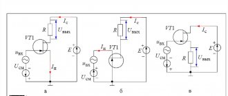
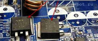
Shown here is a current source as part of a current generator assembled using bipolar transistors.
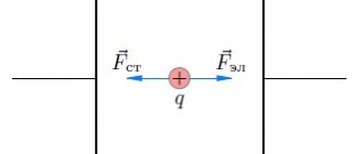
A current source or generator is usually called a two-terminal network that creates a current that does not depend on the load resistance connected to it. And often this name is given to any source of electrical voltage (socket, generator, battery, etc.). But speaking only in a physical sense, such a designation cannot be called correct; on the contrary, voltage sources used for domestic purposes can rather be called sources of EMF.
The above circuit contains a current source as part of the equivalent circuit of a tripolar transistor. The arrow serves as an indicator of the positive direction of the current. In this case, the current generated by this source depends on the voltage in another section of this circuit.
The difference between ideal and real current sources.
An ideal current source has a voltage at the terminals that depends only on what resistance appears on the external circuit: U=L*R
To determine how much power the current source supplies to the network, the following formula is used: P=L 2 *R
In this case, the following equation should be taken into account: L=const
This makes it possible to understand that the power and voltage released by the current source will increase without limit if the resistance increases.
A real current source can be described in a linear approximation by internal resistance. In this it is very similar to a conventional EMF source. The difference between them is as follows: as the internal resistance increases, the current source approaches the ideal parameters, and the EMF source approaches the ideal as the internal resistance decreases.
A real current source with an internal resistance index r and a real EMF source will be equivalent if the following conditions are met:
A real current source will have a voltage across its terminals:
With a current equal to:
And power, determined by the formula:
An inductor through which current from an external source passed for some time after it was turned off can be called a current source.
This explains the contact arcing that occurs when an inductive load is switched off quickly. Gap breakdown occurs due to the conservation of current during a sharp increase in the resistance level.
If the primary winding of a transformer is connected to a powerful alternating current line, its secondary winding can be considered as an ideal source of current , but alternating rather than direct, which results in the impossibility of opening its secondary circuit. This means that the secondary winding must be bypassed.
Read also: Operating principle of a reversible magnetic starter
A real generator has a number of limitations, among which one should be noted - the limitation on the output voltage. For example, a real current source operates only with that voltage range, the upper threshold of which depends on what the voltage supplying the source will be. This leads to some load restrictions.
This current source has found wide application in many fields. For example, for working in conjunction with differential amplifiers and measuring bridges in analog circuitry.
Current source
(in the theory of electrical circuits) - an element, a two-terminal network, the current strength through which does not depend on the voltage at its terminals (poles).
current generator
and
ideal current source
are also used .
The current source is used as a simple model of some real sources
electrical energy or as part of more complex models of real sources containing other electrical elements. It should be noted that the electrical characteristics of real sources may be close to the properties of a current source or its opposite - a voltage source.
In electrical engineering, a current source is any source of electrical energy.
Operating principle
Each marking of current sources determines the principle of its operation. In a standard situation, energy is generated through the interaction of component parts, namely:
- Mechanical type. As a result of the interaction of mechanism parts, friction occurs. Due to this phenomenon, static electricity arises and is converted into current.
- Mechanical structures work by producing sequentially moving charged particles. The phenomenon occurs due to the interaction of a chemical element with an electrolyte. Charged particles leave the structure of the metal crystal lattice, becoming part of the conducting liquid.
- Solar batteries (light sources) work by knocking out charged particles from a dielectric (silicon) base under the influence of a light flux. This creates constant tension.
- Thermal. As a rule, these are 2 metal bases connected in series. One part heats up, while the other remains cooled. When the temperature regime changes, a temperature difference occurs, resulting in the movement of charged particles.
You might be interested in this: Features of the electrician profession
Important! Any change in the structure of a substance can lead to irreversible consequences that will manifest themselves during the operation of the device.
Properties [edit | edit code ]
Ideal current source [edit | edit code]
The strength of the current flowing through an ideal current source is always the same by definition:
I = const >>
The voltage at the terminals of an ideal current source ( not to be confused with a real source!
) depends only on the resistance R of the load connected to it:
U = I ⋅ R
Power supplied by the current source to the load:
P = I 2 ⋅ R <2>cdot R>
Since the current through an ideal current source is always the same, the voltage at its terminals and the power transmitted by it to the load increase with increasing load resistance, reaching infinite values in the limit.
Real source[edit | edit code]
In a linear approximation, any real
a current source (not to be confused with the current source described above - a model!) or another two-terminal network can be represented in the form of a model containing at least two elements: an ideal source and internal resistance (conductivity).
One of the two simplest models - Thevenin's model - contains an EMF source connected in series with a resistance, and the other, opposite to it, Norton's model, contains a current source connected in parallel with conductivity (i.e. an ideal resistor, the properties of which are usually characterized by the conductivity value). Accordingly, a real
source in a linear approximation can be described using two parameters: EMF E >> voltage source (or current I of the current source) and internal resistance r (or internal conductivity y = 1 / r).
It can be shown that a real current source with internal resistance r is equivalent to a real emf source having internal resistance r and emf E = I ⋅ r >=Icdot r> .
Read also: Engine power for grinder
The voltage at the terminals of a real current source is
U out = IR ⋅ r R + r = IR 1 + R / r. < ext>=I=I<1+R/r>>.>
The current in the circuit is equal to
I out = I r R + r = I 1 1 + R / r. < ext>=I>=I<1><1+R/r>>.>
The power supplied by a real current source to the network is equal to
P out = I 2 R ( 1 + R / r ) 2 . < ext>=I^<2> ight)^<2>>>.>
Real current generators have various limitations (for example, on the voltage at its output), as well as nonlinear dependencies on external conditions. In particular, real current generators create electric current only in a certain voltage range, the upper threshold of which depends on the supply voltage of the source. Thus, real current sources have load limitations.
Regulations
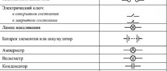
Taking into account the large number of electrical elements, a number of normative documents have been developed for their alphanumeric (hereinafter referred to as BO) and conventional graphic designations (UGO) to eliminate discrepancies. Below is a table showing the main standards.
Table 1. Standards for graphic designation of individual elements in installation and circuit diagrams.
| GOST number | Short description |
| 2.710 81 | This document contains GOST requirements for BO of various types of electrical elements, including electrical appliances. |
| 2.747 68 | Requirements for the dimensions of displaying elements in graphical form. |
| 21.614 88 | Accepted codes for electrical and wiring plans. |
| 2.755 87 | Display of switching devices and contact connections on diagrams |
| 2.756 76 | Standards for sensing parts of electromechanical equipment. |
| 2.709 89 | This standard regulates the standards in accordance with which contact connections and wires are indicated on diagrams. |
| 21.404 85 | Schematic symbols for equipment used in automation systems |
It should be taken into account that the element base changes over time, and accordingly changes are made to regulatory documents, although this process is more inert. Let's give a simple example: RCDs and automatic circuit breakers have been widely used in Russia for more than a decade, but there is still no single standard according to GOST 2.755-87 for these devices, unlike circuit breakers. It is quite possible that this issue will be resolved in the near future. To keep abreast of such innovations, professionals monitor changes in regulatory documents; amateurs do not have to do this; it is enough to know the decoding of the main symbols.
Examples [edit | edit code]
The current source is an inductor through which current flowed from an external source for some time ( t ≪ L / R ) after the source was turned off. This explains the sparking of the contacts when the inductive load is quickly turned off: the desire to maintain current with a sharp increase in resistance (the appearance of an air gap) leads to a sharp increase in the voltage between the contacts and to breakdown of the gap.
The secondary winding of a current transformer, the primary winding of which is connected in series with a powerful alternating current line, can be considered as an almost ideal source of alternating current. Therefore, opening the secondary circuit of the current transformer is unacceptable. Instead, if recommutation is necessary in the secondary winding circuit (without disconnecting the line), this winding is first bypassed.
Testing the assembled device
The prototype was first tested with a 12V/10W white LED and the connected oscilloscope shows that there is no unnecessary oscillation. And then tested up to 12A using the old 0.1ohm/20W resistor instead of the 1ohm/5W resistor. Of course, the radiator was also changed to a more powerful one. According to the data sheet, the IRF3205 transistor can withstand a current of 100 A, but with sufficient cooling.
Now for a few things to consider when assembling. First, a separate 12V power supply should be used for the DC oscillator circuit. Then, if you decide to use a different op amp, then choose a bus-to-line op amp as it will be better than the LM358 op amp that was used here. It is also important to pay attention to the ratings of the components in the power electronics circuit. Wrong choice can lead to serious disasters such as overheating.
If necessary, you can replace the reference voltage with an analog (or digitally controlled pulse-width signal). This is more conventional and easier to understand, so I won't go into detail now. In such cases, the unused second op-amp will act as a unity gain buffer—a voltage follower. The input impedance of the op amp buffer is very high and the output impedance is very low. This inclusion helps solve resistance matching problems. This inclusion helps solve resistance matching problems.
Application [ edit | edit code ]
Current sources are widely used in analog circuitry, for example, to power measuring bridges, to power stages of differential amplifiers, in particular operational amplifiers.
The concept of a current generator is used to represent real electronic components in the form of equivalent circuits. To describe the active elements for them, equivalent circuits containing controlled generators are introduced:
- Voltage controlled current source (VCS). Mainly used for field-effect transistors and vacuum tubes.
- Current controlled current source (CCU). Typically used for bipolar transistors.
In the current mirror circuit (Figure 2), the load current in the right branch is set equal to the reference current in the left branch, so that with respect to the load R2
this circuit acts as a current source.
Letter designations
In electrical diagrams, in addition to graphic symbols, alphabetic symbols are also used, since without the latter, reading the drawings will be quite problematic. Alphanumeric marking, just like UGO, is regulated by regulatory documents, for electrical this is GOST 7624 55. Below is a table with BO for the main components of electrical circuits.
Letter designations of main elements
Unfortunately, the size of this article does not allow us to provide all the correct graphic and letter symbols, but we have indicated regulatory documents from which all the missing information can be obtained. It should be taken into account that current standards may change depending on the modernization of the technical base, therefore, we recommend monitoring the release of new additions to regulations.
Voltage sources based on the phenomenon of electrification by friction (Van de Graaff generator).
The oldest method of generating electricity is friction. If you take a glass or ebonite rod and rub it with a piece of fur or silk, it will charge. The Van de Graaff generator operates on this very principle (Fig. 3.1.).
Figure 3.1. Van de Graaff generator.
The Van de Graaff generator is capable of producing voltages of millions of volts. But, unfortunately, this device is not used anywhere except in scientific research, and even in physics classrooms.