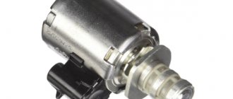
Let's start with the fact that the automatic transmission solenoid is actually an electromagnetic valve-regulator. The main task is the timely opening and closing of the oil channel through which ATF is supplied under pressure.
It is important to understand that automatic transmission solenoids, like any other devices, have a limited service life, may malfunction or fail under certain conditions. Next, we will look at what solenoid malfunctions often occur, what to do in this situation and how to check the automatic transmission solenoids for functionality
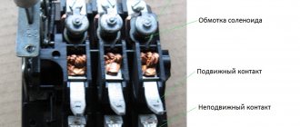
Description and principle of operation of the solenoid
A linear solenoid operates on the same basic principle as the electromechanical relay described in the previous lesson, and just like relays, they can also be switched and controlled using transistors or MOSFETs. A linear solenoid is an electromagnetic device that converts electrical energy into a mechanical pushing or pulling force or movement. A linear solenoid basically consists of an electrical coil wound around a cylindrical tube with a ferromagnetic drive or "plunger" that can freely move or slide the "IN" and "OUT" in the coil housing. Types of solenoids are shown in the figure below.
Solenoids can be used to electrically open doors and latches, open or close valves, move and control robotic limbs and machinery, and even turn on electrical switches just by applying power to its coil. Solenoids are available in a variety of formats, with the most common types being the linear solenoid, also known as linear electromechanical actuator (LEMA) and rotary solenoid.
Solenoid and scope of application
Both types of solenoids, linear and rotary, are available in hold (constant voltage) or latch (ON-OFF pulse) form, with latch types used in energized or power-off applications. Linear solenoids can also be designed for proportional motion control, where the position of the plunger is proportional to the power input. When electric current flows through a conductor, it generates a magnetic field, and the direction of this magnetic field relative to its north and south poles is determined by the direction of current flow within the wire.
This coil of wire becomes an "electromagnet" with its own north and south poles, just like a permanent magnet. The strength of this magnetic field can be increased or decreased either by controlling the amount of current flowing through the coil or by changing the number of turns or loops the coil has. An example of an "electromagnet" is given below.
Recommendations
- The Cambridge Advanced Learner's Dictionary
gives two phonetic variants /ˈsəʊ.lə.nɔɪd/ and /ˈsoʊ.lə.nɔɪd/."Solenoid: meaning in the Cambridge English Dictionary."
dictionary.cambridge.org
. Archived from the original on January 16, 2022. Retrieved January 16, 2017. - The French term was coined in 1823 from σωλήν "channel, pipe" and the -oid (-o-ειδής) suffix. "Solenoid" in: Trésor de la langue française informatisé
.
The Greek σωληνοειδ, "trumpet shape", is first attested in Aeneas Tacticus (4th century BC). Henry George Liddell, Robert Scott, A Greek-English Lexicon
(1843).
See also "Solenoid". Online Dictionary of Etymology
. Archived from the original July 28, 2011 - Session of the Academy of Sciences
of December 22, 1823, printed in: Ampère, "Mémoire sur la théorie mathématique des phénomènes électro-Dynamiques",
Mémoires de l'Académie royale des Sciences de l'Institut de France
6 (1827), Paris , F. Didot, S. 267ff.
(and figs. 29–33). "l'assemblage de tous les circuit qui l'entourent [namely l'arc], Assemblage auquel j'ai donné le nom de electro-dynamic solenoid
, du mot grec σωληνοειδὴς, dont laignation ex prime précising ce qui a la forme d' un canal, c'est-à-dire la surface de cette forme sur laquelle se Trouvent tous les circuit” (p. 267). - or, what is the same, the diameter of the coil is assumed to be infinitely small (Ampère 1823, p. 267: “des courants électriques formants de très-petits circuit autour de cette ligne, dans des plan infiniment rapprochés qui lui soient perpendiculaires”).
- [[1]]
- Giles, David. Introduction to magnetism and magnetic materials. CRC press, page 48, 2015.
- "Archive copy" (PDF). Archived (PDF) from the original April 10, 2014. Retrieved March 28, 2013.CS1 maint: archived copy as title (site link)
- Müller, Karl Friedrich (1 May 1926). "Berechnung der Induktivität von Spulen" [Calculation of the inductance of coils]. Archiv für Elektrotechnik
(in German).
17
(3):336–353. Doi:10.1007/BF01655986. ISSN 1432-0487. S2CID 123686159. - Callaghan, Edmund E.; Maslen, Stephen H. (October 1, 1960). "Magnetic field of a finite solenoid". NASA Technical Reports
. NASA-TN-D-465 (E-900). - Caciagli, Alessio; Baars, Roel J.; Phillips, Albert P.; Kuipers, Bonny W. M. (2018). "An exact expression for the magnetic field of a finite cylinder with arbitrary uniform magnetization". Journal of Magnetism and Magnetic Materials
.
456
:423–432. doi:10.1016/j.jmmm.2018.02.003. ISSN 0304-8853. - Course, Andre; Karalis, Aristeidis; Moffatt, Robert; Joannopoulos, J.D.; Fisher, Peter; Soljacic, Marin (6 July 2007). "Wireless energy transfer using tightly coupled magnetic resonances". The science
.
317
(5834):83–86. Doi:10.1126/science.1143254. PMID 17556549. S2CID 17105396. - Zhou, Wenshen; Huang, Shao Ying (September 28, 2022). "A New Coil Design for Broadband Wireless Power Transmission". 2022 International Applied Computational Electromagnetics Society (ACES) Symposium
. - Ren, Zhi Hua; Huang, Shao Ying (August 2022). "Design of a short solenoid with uniform B1 for portable low-field magnetic resonance imaging using genetic algorithm." Proc.
26th ISMRM : 1720. - Jian, L.; Shi, Y.; Liang, J.; Liu, C.; Xu, G. (June 2013). "A Novel Targeted Magnetic Fluid Hyperthermia System Using an HTS Coil Array for Tumor Treatment." IEEE Transactions on Applied Superconductivity
.
23
(3): 4400104. doi:10.1109/TASC.2012.2230051. S2CID 44197357. - Zhou, Wenshen; Huang, Shao Ying (July 2022). "An accurate model for quickly calculating the resonant frequency of an irregular solenoid". IEEE Proceedings of Microwave Theory and Techniques
.
67
(7):2663–2673. Doi:10.1109/TMTT.2019.2915514. S2CID 182038533. - Zhou, Wenshen; Huang, Shao Ying. "An accurate model code for quickly calculating the resonant frequency of an irregular solenoid." Magazine citation required | log = (Help)
- Zhou, Wenshen; Huang, Shao Ying (October 2022). "Modeling the intrinsic capacitance of an irregular solenoid". IEEE Transactions on Electromagnetic Compatibility
: 1–9. Doi:10.1109/TEMC.2020.3031075. - Zhou, Wenshen; Huang, Shao Ying. "Precision Model Code for Determining the Intrinsic Capacitance of Non-Standard Solenoids." Magazine citation required | log = (Help)
- D. Howard Dellinger; L. E. Whittemore and R. S. Ould (1924). Radio instruments and measurements
.
NBS Circular
.
C74
. ISBN 9780849302527. Retrieved September 7, 2009. - "How to hold a doorbell." Popular Science
(March 1975). March 1975. p. 117. Archived from the original May 14, 2018. Retrieved November 29, 2022.
Magnetic field created by the coil
When an electric current passes through the windings of the coils, it behaves like an electromagnet and the plunger, which is located inside the coil, is attracted to the center of the coil by the magnetic flux inside the body of the coils, which in turn is compressed by a small spring attached to one end of the plunger. The force and speed of movement of the plungers are determined by the strength of the magnetic flux generated inside the coil.
When the supply current is turned off (de-energized), the electromagnetic field previously created by the coil is destroyed, and the energy stored in the compressed spring forces the piston to return to its original resting position. This back and forth movement of the plunger is known as the "stroke" of the solenoids, in other words, the maximum distance the plunger can travel in the "in" or "out" direction, for example 0-30mm.
This type of solenoid is usually called a linear solenoid due to the linear directional movement and plunger action. Linear solenoids are available in two basic configurations, called "pull type" since it pulls the connected load toward itself when they are energized, and "push type" which act in the opposite direction, pushing it away from it when power is applied. Both push-pull and push-pull types typically have the same design, with differences in the location of the return spring and the design of the plunger.
Magnetic field created inside.
General information
Blue and green laser beams are clearly visible through the colloidal mixture due to the Tyndall effect
In this article we will talk about interesting and unusual ferromagnetic liquids
.
If they are magnetized by exposing them to a magnetic field, these liquids form interesting folds on the surface. Ferromagnetic liquids are colloidal systems consisting of nanoparticles
about 10 nm in size distributed in suspension in water or other carrier fluid.
Most of these carrier liquids are organic solvents, that is, liquids in which another substance can be dissolved. Colloidal substances
are liquids that are mixtures of a carrier liquid and particles of another substance.
Usually these particles do not sink to the bottom as sediment, and this makes the colloidal substance fairly homogeneous. This property especially applies to ferromagnetic liquids. In addition to the particles' natural properties of remaining suspended in the ferrofluid, these particles are coated with a special substance called a surfactant
, which prevents the particles from sticking together, and helps the ferrofluid remain a liquid.
You can observe van der Waals forces in action when geckos, anole lizards, skinks and some insects move along vertical surfaces of walls, or even along the ceiling
Green anole lizard
Surfactant molecules attach to the nanoparticles and surround each particle, thereby creating a buffer around the particle. Attraction between nanoparticles is governed by van der Waals forces
, which weaken as the distance between these particles increases. Therefore, when the distance between nanoparticles increases due to the surfactant, the attraction between these particles weakens.
Magnetite
In some cases, surfactants work differently. Their molecules attach to the nanoparticle so that their outer polarity is the same over the entire outer surface (for example, the outer shell becomes positively charged). Thus, a shell with a certain charge is formed around each nanoparticle. Since the shells of all nanoparticles are equally charged, they repel each other because like charges repel each other. This prevents sticking.
Magnetite, like a natural magnet
We talked a little about carrier fluids. But what do nanoparticles themselves consist of? Sometimes particles of magnetite, a mineral with magnetic properties, are used for this purpose. Magnetite
is a naturally occurring mineral that can be easily magnetized. It is worth noting that in some special cases magnetite has the properties of a permanent magnet, that is, under normal conditions its magnetic properties are constant and unchanging. Magnetite particles in ferromagnetic liquids are not permanent magnets, that is, they can be magnetized using a magnetic field, but this magnetization disappears as soon as the magnetic field ceases to act on them. Also, for the production of ferromagnetic liquids, highly dispersed powders of metals with magnetic properties and some ferrimagnetic materials are used.
Pull-type linear solenoid design
Linear solenoids are useful in many applications that require open or closed motion (such as inside or outside), such as electronically controlled door locks, pneumatic or hydraulic control valves, robotics, automotive engine control, irrigation valves for garden watering, and even for doorbell. They are available as open frame, closed frame or sealed tubular types.
Material on the topic: What is a capacitor
Rotary solenoid
Most electromagnetic solenoids are linear devices, producing linear force or forward and reverse motion. However, there are also rotary solenoids that produce angular or rotational movement from a neutral position in either clockwise, counterclockwise, or both directions (bidirectional). Rotary solenoids can be used to replace small DC motors or stepper motors if the angular motion is very small and the rotation angle is the angle offset from the start to end position.
It will be interesting➡ Varistors - what they are, operating principle, characteristics and parameters.
Typically available rotary solenoids have movements of 25, 35, 45, 60 and 90 o, as well as multiple movements to and from a specific angle, such as self-restoring in two positions or returning to zero rotation, for example, from 0 to 90- to -0 ° , self-healing in 3 positions, for example from 0 ° to +45 ° or from 0 ° to -45 °, and locking in 2 positions.
Solenoid in a metal housing.
Rotating solenoids produce rotational motion when energized, de-energized, or changing the polarity of the electromagnetic field changes the position of the permanent magnet rotor. Their design consists of an electrical coil wound around a steel frame with a magnetic disk connected to an output shaft located above the coil.
When the coil is energized, the electromagnetic field generates multiple north and south poles, which repel the adjacent permanent magnetic poles of the disk, causing it to rotate at an angle determined by the mechanical design of the rotating solenoid.
Rotary solenoids are used in vending machines or gaming machines to operate valves, chamber shutters with special high speed, low energy or high force or torque adjustable positioning solenoids such as those used in dot matrix printers, typewriters, vending machines or cars.
Solenoid device diagram.
Electromagnetic switching
Typically solenoids, linear or rotary, operate with a constant voltage applied, but they can also be used with sinusoidal AC voltages by using full-wave bridge rectifiers to rectify the supply, which can then be used to switch a DC solenoid. Small DC type solenoids can be easily controlled using transistor or MOSFET and are ideal for use in robotic applications.
However, as we saw earlier with electromechanical relays, linear solenoids are "inductive" devices, so some electrical protection through the solenoid coil is required to prevent high back EMFs from damaging the solid state switching device. In this case, a standard "Flywheel Diode" is used, but you can also use a Zener diode or a low value varistor.
Solenoid valve device.
Content
- 1 Infinite Continuous Solenoid 1.1 Inside
- 1.2 beyond
- 1.3 Quantitative description
- 6.1 Electromechanical solenoid 6.1.1 Proportional solenoid
Reduced solenoid power consumption
One of the main disadvantages of solenoids, especially a linear solenoid, is that they are "inductive devices" made from spools of wire. This means that the solenoid coil converts some of the electrical energy used to operate them into "heat" due to the resistance of the wire. In other words, when connected to a power source for a long time, they get hot, and the longer the time that power is applied to the solenoid coil, the hotter it gets. Also, as the coil heats up, its electrical resistance also changes, allowing more current to flow, increasing its temperature.
With a constant input voltage applied to the coil, the solenoid coil has no chance to cool down because the input power is always on. To reduce this self-generated heating effect, it is necessary to reduce either the amount of time the coil is energized or reduce the amount of current flowing through it. One way to draw less current is to apply a suitable high enough voltage to the electromagnetic coil to provide the necessary electromagnetic field to operate and seat the plunger, but then activate once to reduce the supply voltage to the coils to a level sufficient to keep the plunger in a "seated" state. or closed position.
Using this method, the solenoid can be connected to its voltage source indefinitely (continuous duty cycle) as the power consumed by the coil and the heat generated are greatly reduced, which can be up to 85-90% when using a suitable power resistor. However, the power consumed by the resistor will also generate a certain amount of heat, I 2 R (Ohm's law), and this must also be taken into account.
Use of ferromagnetic fluids
Ferromagnetic fluids react to a magnet and follow it, so with the help of a magnet they can either be moved from place to place or held in the desired place. Thanks to this, they have found wide application in science, technology and medicine.
Like lubricants
Ferromagnetic fluids are used as lubricants in rotating mechanisms. Like traditional lubricants, they help reduce friction between mechanical parts, but their main advantage is that ferrofluids can be easily held in position using a magnet or magnetic field.
Ferromagnetic fluid under the influence of a strong magnet
In sealing seals
In some cases, sealing seals may be in the form of a liquid - in this situation it is very convenient to use ferromagnetic liquids. They are used, for example, to seal the inside of a hard disk drive, which contains the spindle drive, the hard drives themselves, and the servo drive of the head unit. Magnets hold the ferromagnetic fluid in the right place, and it, in turn, does not let dust from outside into the hermetic zone of the hard drive, and helps prevent damage to the disks. Some ferrofluid manufacturers sell the ferrofluid itself for this purpose, and some develop and produce a complete set of ferrofluid seals and do not sell the fluid separately to prevent its misuse.
In art
Some sculptors and artists use ferrofluid to create modern works of art. In addition to three-dimensional and moving sculptures, which demonstrate in all their glory the play of folds of ferromagnetic liquid under the influence of a magnet, artists also create flat paintings from this liquid. Ferromagnetic fluids do not mix with water and water-based paints, so such paints and pigments (such as fluorescent) are added to the ferromagnetic fluid and then moved with a magnet to create colorful shapes. There are many interesting examples of paintings and sculptures made from ferromagnetic fluid on YouTube.
Ferromagnetic fluid under the influence of a strong magnet
In sound reproduction systems
In electrodynamic loudspeakers of sound reproduction systems, ferromagnetic fluid is used to cool the voice coil. Due to the low energy efficiency of sound reproduction systems, most electrical energy is converted into heat during operation, and this heat can damage the voice coil if it is not cooled. Ferromagnetic fluids remove this heat from the voice coil, and a magnet holds it in the gap, just like in the other systems described above.
Ferromagnetic fluids are also used to dampen a diffuser with a coil at resonant frequencies. This smoothes out the amplitude-frequency response of the speaker. To do this, ferromagnetic fluids are placed in the gap between the voice coil and the magnet.
When choosing a ferromagnetic fluid, they are guided by knowledge of the environment in which it will be used. For example, when choosing a carrier fluid or when choosing the viscosity of a ferromagnetic fluid, factors such as the humidity of the environment in which the fluid will be used, or whether the device in which the ferromagnetic fluid is used will come into contact with water are taken into account.
In medicine
Ferromagnetic fluids have several uses in medicine. Currently, scientists are conducting research on the use of ferromagnetic liquids as carriers of drugs and other drugs needed by patients. Using a magnet, these medications are moved to a specific area of the body. Typically, in this case, nanoparticles are coated with a layer of drug, after which a ferromagnetic liquid is introduced into the body (usually by injection) and held in place with a magnet until the drug has the desired effect. There are a number of other methods for localized delivery of therapeutic drugs, but scientists hope this method will provide the greatest precision.
Another interesting application of ferromagnetic liquids in medicine is heat therapy of certain areas of the body. It is most often used to kill cancer cells. To do this, a ferromagnetic liquid is injected into the body, and then the ferromagnetic particles are forced to oscillate at a high frequency using electromagnets. This generates a large amount of heat, and high temperatures destroy tissue in this area, killing cancer cells.
In diagnostics of magnetic media
Ferromagnetic fluids are used to determine the structure of the magnetic domains of various magnetic media, such as magnetic tape drives, hard drives and credit cards. They are also used to check defects on the surface of materials that are not related to magnetic media, such as welding seams, as well as natural minerals and metals. This is used, for example, in the production of miniature components. To do this, the surface of the material is coated with a ferromagnetic liquid, and it is distributed over this surface in accordance with the magnetic field of the material. After the carrier liquid has evaporated, ferromagnetic particles remain on the surface, from which the structure of the surface magnetic field is determined. This usually requires a microscope. This method is used not only to test the surface of magnetic media and materials described above, but also in forensic examination. For example, ferromagnetic fluid can be used to determine serial numbers on firearms that have been removed at home.
In heat exchangers
Overheating is a widespread problem in electronics. To avoid damage, electronic devices must be cooled. Ferromagnetic fluids are sometimes used for these purposes, for example in loudspeakers and some microelectronic devices. At the beginning of this article, when we discussed the properties of ferromagnetic liquids, we already mentioned that at high temperatures (Curie temperatures), ferromagnetic liquids lose their magnetic properties. This feature of ferromagnetic fluids is used in cooling systems. During cooling, the ferromagnetic fluid held near the part being cooled loses its magnetic properties once it reaches the Curie temperature. The magnet stops holding it and it is replaced by a cold ferromagnetic liquid, which still has magnetic properties. The new liquid is heated, and the heated one is cooled, and the process is repeated periodically. In this case, the magnet acts as a pump, since it helps to replace the less magnetized hot liquid with the more magnetized cold one.
Solenoid Duty Cycle
Another more practical way of reducing the heat generated by the solenoid coil is to use "intermittent duty cycle". Intermittent duty cycle means that the coil is switched ON and OFF repeatedly at a suitable frequency to activate the plunger mechanism but prevent it from de-energizing during the OFF period. Intermittent switching of the duty cycle is a very effective way of reducing the total power consumed by the coil.
The duty cycle (% ED) of a solenoid is the portion of the "ON" time when the solenoid is energized, and is the ratio of the "ON" time to the total "ON" and "OFF" times for one complete cycle of operation. In other words, the cycle time is equal to the on time plus the off time. The duty cycle is expressed as a percentage, for example:
It will be interesting➡ What is an inductor and why is it sometimes called a choke
Then if the solenoid is on or on for 30 seconds and then off for 90 seconds before turning on again, one full cycle, the total on/off cycle time will be 120 seconds, (30 + 90) so the duty cycle of the solenoids will be calculated as 30/120 sec or 25%. This means that you can determine the maximum on time of the solenoids if you know the duty cycle and off time values.
For example, the off time is 15 seconds, the duty cycle is 40%, so the on time is 10 seconds. A solenoid with a 100% duty cycle rating means it has a constant voltage rating and can therefore be left on or constantly on without overheating or damage. In this lesson on solenoids, we looked at both the linear solenoid and the rotary solenoid as an electromechanical actuator that can be used as an output device to control a physical process. In the next lesson we will continue to look at output devices called actuators and the device that again converts the electrical signal into a corresponding rotational motion using electromagnetism. The type of output device we will look at in the next lesson is the DC motor.
Material on the topic: What is a time relay.
Solenoid in package
Indirect acting solenoids
This type of solenoid is more complex and will take more time to explain the mechanism of its operation. Simply put, an indirect acting solenoid consists of two valves connected into one mechanism. The main valve is a spool that works according to the principle described above, the second mechanism used is the pilot valve, which is located between the spool and the electromagnet. The control valve is a small direct-acting solenoid that activates the push of the large spool. Please note that the solenoid shown in this image is a direct acting solenoid as it acts directly on the control valve, but the entire assembly is an indirect acting solenoid.
The main difference between direct acting and indirect acting solenoids is how they interact with the mechanical parts of the marker. Direct acting solenoids work directly with the elements of the marker mechanism. Indirect acting solenoids use air flow to control the spool. The main reason for the existence of indirect acting solenoids is their incredibly low power consumption compared to direct acting solenoids. For example, if a direct acting solenoid requires 4 watts to affect a mechanism, then an indirect acting solenoid only needs 0.5 watts to effect the same effect.
Solenoid operation diagram.
Next, solenoids are divided according to the number of threads. To function, the solenoid must have at least one hole through which air enters the solenoid, one hole through which air enters the mechanism, and one hole through which air is released. But in most cases, a design is used with two holes for supplying air to the marker mechanism and two air release holes. Currently, there are mainly three main types of solenoids in use:
- Four way spool valve. This type is used in most all-electro-pneumatic markers, where air is used to move the piston back and forth. For example Ego, Angel, Shocker, Dye Matrix, etc. The incorrectly named three way valve on cockers is also an example of a four-way piston.
- Three-way spool, closed when at rest (3-way spool normally closed). This is a three-flow valve that supplies air when voltage is applied to it. When this solenoid is at rest, it does not supply any pressure, for example pVI Shocker, Invert Mini.
- Three-way spool, open when at rest (3-way spool normally open). This is a three-flow valve that supplies pressure at rest, and shuts off the air flow when voltage is applied to it, such as Ion.
The control valve in the solenoid is always three-flow, closed at rest. When voltage is applied to the solenoid, the control valve opens and supplies air in order to move the spool, which, in turn, can be either three-flow or four-flow.
Each indirect acting solenoid is divided into three segments: coil, pilot and spool. The coil is the only electromagnetic part of the entire mechanism. It consists of copper wire wrapped around a metal casing, inside which there is a metal rod, which is the opposite magnetic component of the valve. The rod is made of steel and has a spring at one end. At the opposite end of the solenoid is the spool, which is the valve and the main moving part of the solenoid. Spools are usually made of brass or aluminum depending on the manufacturer.
It will be interesting➡ Diode bridge - what is it?
There are also various gaskets on the spool to redirect air flow. And finally, the last part of the solenoid is the control valve, which is the “mediator” between the movement of the coil rod and the spool. The main component for a control valve is a round piston that moves the spool to the open position. The piston is a small plastic disc with a gasket around it. Behind the piston is a small actuator, a piece to hold the actuator in place, and a small plug located inside the actuator. Most of these components, like the control valve body, are made of polymers to improve sliding and sealing.
Interesting material for familiarization: what are variastors.
In conclusion of the article, what is dwell? This is the time during which voltage is applied to the solenoid (respectively, the path of the marker bolt to the forward position + the time that the bolt is in the forward position, releasing air). If you lower the dwell setting too much, you will have to compensate for the shorter time the bolt stays in the forward position by increasing the operating pressure of the marker, which will not be beneficial for your marker. A too high value of the dwell parameter will lead to excessive air consumption, battery charge and greater wear of the solenoid itself.
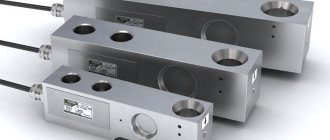
Two identical solenoids.
Inductance
See also: Inductance with physical symmetry
As shown above, the magnetic flux density B { displaystyle B} inside the coil is almost constant and is given by
B = μ 0 N i l , { displaystyle B = mu _ {0} { frac {NI} {l)),}
where μ
0 is the magnetic constant, N { displaystyle N} the number of turns, i { displaystyle I} current and l { displaystyle l} the length of the coil.
Ignoring end effects, the total magnetic flux through the coil is obtained by multiplying the flux density B { displaystyle B} by the cross-sectional area A { displaystyle A}: Φ = μ 0 N i A l.
{ displaystyle Phi = mu _ {0} { frac {NIA} {l}}.} Combining this with the definition of inductance
L = N Φ I , { displaystyle L = { frac {N Phi} {I)),}
the inductance of the solenoid is
L = μ 0 N 2 A l . { displaystyle L=mu_{0}{frac {N^{2}A}{l)).}
An inductance table for short solenoids with different diameter-to-length ratios was calculated by Dellinger, Whittemore and Ould.[19]
This, as well as the inductance of more complex shapes, can be obtained from Maxwell's Equation. For rigid air-core coils, the inductance depends on the coil geometry and the number of turns and is independent of current.
A similar analysis applies to a solenoid with a magnetic core, but only if the length of the coil is much greater than the product of the relative permeability of the magnetic core and the diameter. This limits simple analysis to low permeability cores or very long thin solenoids. The presence of the core can be taken into account in the above equations by replacing the magnetic constant μ0
with
μ
or
μ0μр
, where
μ
represents the permeability and
μр is
the relative permeability. Note that since the permeability of ferromagnetic materials varies with applied magnetic flux, the inductance of a ferromagnetic core coil generally varies with current.
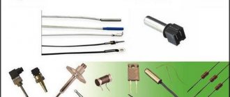
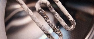
How to check functionality
A conductor in the shape of a spiral in which a magnetic field arises is called a solenoid. Used in cars and designed to switch sensors and valves at a distance. Thus, if a valve or any sensor stops functioning, then, first of all, the solenoid is checked.
To check you will need the following:
- compressor;
- diagnostic equipment;
- various tools - screwdrivers, wrenches and others.
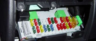
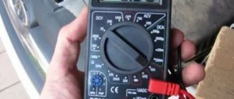
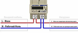
To check the solenoid, it must be switched to “ohmmeter” mode. You can find the solenoid in a car using the technical documentation that comes with each vehicle. The solenoid must be connected to the on-board computer. Pay attention to the condition of the valve. It can be closed or open.
- The next step is to check the electrical resistance of the solenoid. In your work, you will need to use an ohmmeter, which should be connected to the terminals of the component. The resistance the solenoid should have in hot and cold states is indicated in the technical documentation. Check the component circuit for short circuit. It is necessary to close each contact through the car body. Over a long period of operation, a large number of contaminant components accumulate in the solenoid. If possible, wash the solenoid in gasoline. It is possible that you have to deal with a non-separable component. Then you will have to replace the old solenoid with a new one, and you can be sure that the problem is fixed.
- The solenoid is a source of a powerful magnetic field. As a result, a large number of metal microparticles accumulate inside. They settle on the walls of the channels and soon begin to interfere with the normal operation of the valve. Moving parts work intermittently. Metal microparticles can be removed using a compressor. High air pressure will remove all the debris that has accumulated over several years or months of use. Don’t forget to pay attention to what state the valve should be in in normal condition.
- If the solenoid is closed in the normal position, then perform a simple test. Disconnect the device from the power source. After this, direct a stream of air, which should be retained inside and not exit through the outlet channel. Apply voltage to the solenoid. In this situation, the air stream should begin to exit through the outlet channel. If the conditions are met, then the component can be said to be in a suitable state.
- A different situation will have to be encountered in the case of a normally open solenoid. Once the component has been de-energized, air should begin to escape through the outlet valve. When current is applied, the channel is closed and the air remains inside.
Solenoid valve.
The presence of a short circuit causes low resistance. It can be measured and for this it is necessary to find the electromotive force, as well as its internal resistance. Based on the information received, perform the required calculations. To calculate a short circuit, you only need a tester.
Properties
Ferromagnetic liquids under the influence of a magnetic field are a fascinating sight. Folds similar to cones form on the surface, and when the magnetic field moves, these folds move behind the field. They are located along the lines of force, and their height depends on the strength of the magnetic field. The strength of the magnetic field, in turn, depends on how close the magnet is to the liquid. Below we will discuss the various applications of ferrofluids. All these applications are based on this property of a ferromagnetic fluid to follow a magnetic field.
Disassembled hydrodynamic bearing of a hard disk drive
The properties of ferromagnetic liquids change with temperature. At very high temperatures, known as the Curie temperature, the nanoparticles lose their magnetic properties and the ferromagnetic fluid turns into a normal liquid. Also, over time, the surfactant loses its repulsive properties, and the nanoparticles stick together, so that the properties of the ferromagnetic fluid disappear.