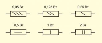
The rotor windings of synchronous generators are powered by special DC sources called exciters.
The exciter power is 0.3-1% of the generator power, and the rated voltage is from 100 to 650 V. The more powerful the generator, the higher the rated excitation voltage usually is.
Modern excitation circuits, in addition to the exciter, contain a large number of auxiliary equipment. The combination of exciter, auxiliary and control devices is usually called the excitation system.
The electrical connection of the exciter to the generator rotor winding is carried out mainly using slip rings and brushes. Brushless excitation systems have been created and are being used.
Excitation systems must be reliable and economical, allow regulation of the excitation current within the required limits, be fast enough, and also provide ceiling excitation in the event of an emergency in the network.
By adjusting the excitation current, they change the voltage of the synchronous generator and the reactive power it supplies to the network. Regulating the generator excitation makes it possible to increase the stability of parallel operation.
During deep voltage drops, which occur, for example, during short circuits, the excitation of generators is forced (rapidly increased), which helps to stop electrical swings and maintain the stability of parallel operation of generators. In addition, high-speed regulation and excitation boost increase the reliability of relay protection and facilitate the conditions for self-starting of electric motors for the auxiliary needs of power plants.
Fig.1. Change in excitation voltage during boost
The most important characteristics of excitation systems are: speed, determined by the rate of voltage rise on the rotor winding during boost V = 0.632(Uf,pot - Uf,nom) / Uf,nomt1 (Fig. 1), and the ratio of the ceiling voltage to the rated excitation voltage Uf,pot / Uf,nom = kf - the so-called boost ratio.
According to GOST, turbogenerators must have kf≥2 , and the rate of increase in excitation is at least 2 1/s. The boost factor for hydrogen generators must be at least 1.8 for collector exciters connected to the generator shaft, and at least 2 for other excitation systems. The rate of rise of the excitation voltage must be at least 1.3 1/s for hydro generators up to 4 MBA inclusive and at least 1.5 1/s for hydro generators of high power.
For powerful hydrogen generators operating for long-distance power transmission, a higher requirement is placed on the excitation systems (kf = 3-4, excitation rise rate up to 10 Uf, nom per second).
The rotor winding and excitation systems of generators with indirect cooling must withstand twice the rated current for 50 s. For generators with direct cooling of the rotor windings, this time is reduced to 20 s, for generators of 800-1000 MW the time is 15 s, 1200 MW - 10 s (GOST 533-85E).
Generator excitation systems can be divided into two groups: independent excitation and self-excitation (dependent excitation).
The first group includes all electric machine exciters of direct and alternating current connected to the generator shaft. The second group consists of excitation systems that receive power directly from the generator terminals through special step-down transformers. This group may include excitation systems with separately installed electric machine exciters driven by alternating current electric motors, which receive power from the auxiliary buses of power plants.
Generator circuits with additional diodes
It is possible to make the generator excitation circuit shorter and more reliable. The excitation current passes only inside the generator and does not pass into the external circuit through the ignition switch. To do this, the excitation current is taken from the generator windings, rectified by a separate small rectifier and sent directly to the excitation winding.
A circuit with additional diodes allows you to protect the battery from accidental discharge through the excitation winding. In such a circuit, the excitation winding is not directly connected to the output of the generator and battery. The excitation current flows not from the output of the diode bridge connected to the battery, but directly from its windings into the excitation winding, through an additional rectifier.
For initial excitation you have to use a battery. The initial excitation current, when the ignition switch is turned on, passes into the excitation winding through the light bulb. The light bulb has a high resistance, so the current flows in the excitation circuit is small (the light bulb lights up), such a current is quite enough to bias the rotor. As soon as the rotor is magnetized, the generator begins to generate voltage and current appears in the windings, this current flows through additional diodes into the excitation winding and the magnetization of the rotor increases, so the generator is excited almost immediately, having received an initial push with a small current through the light bulb. Then the generator operates independently, consuming the required excitation current through additional diodes.
The external excitation circuit remains connected and is used again the next time the engine is started. The light bulb actually separates the generator's initial excitation circuit and the operating excitation circuit. The current of the excitation winding can reach 5 Amperes, but so that the excitation winding cannot consume such current from the battery, there is a light bulb in the initial excitation circuit that limits this current. At first glance, the problem remains - if the generator rotor does not spin and the ignition is on, then the battery is discharged, but discharges a very small current through the light bulb (the light is on)
The current of the light bulb can burn for several days and this will not lead to a complete discharge of a normal battery. A very important advantage of such a circuit is that the light bulb not only limits the battery discharge current through the excitation winding, but that it becomes a very useful indicator of the state of the generator-battery system and will allow you to monitor the charging process of the battery and the serviceability - failure of the generator
Generator circuit with additional diodes and voltage regulator type L (D+)
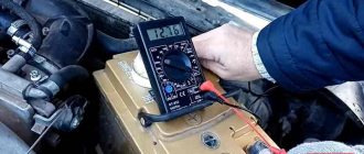
How to test a generator using a light bulb and a multimeter
Checking the functionality of the generator is possible in several ways; for this you will need to use certain methods - this could be measuring the output current of the generator, the voltage drop on the wires connecting the current output of the generator to the battery, or checking the regulated voltage.
For diagnostics, you will need a multimeter, a battery and a light bulb with wires soldered to its contacts, wires to connect the generator to the battery, and you can also take a drill with a specific head - it may be needed to rotate the rotor through the pulley nut.
The connection diagram is as follows: output terminal “B+” and rotor D+. The lamp fits between the generator output and the D+ contact. Then the power wires connect the negative on the battery to the generator ground. “Plus” from the battery, respectively, with the plus of the generator and the B+ terminal. The structure is securely fixed in a vice and connected.
The multimeter is switched to DC voltage measurement mode, one probe is connected to the “plus” of the battery, and the second to the “minus”. If everything is in order, the lamp will light up, and the voltage should be 12.4 volts.
Then, use a drill to spin the generator. At this moment, the lamp should go out and the voltage should rise to 14.9 V. Then a load is added - for this purpose you can use an H4 halogen lamp. It is also hung on the battery terminals, after which it should light up.
Next, the generator is turned again with a drill. The voltmeter should record a voltage of 13.9 volts. Without a drill, the battery should produce approximately 12.2 volts. If this does not happen or the readings are very different, then the generator is faulty.
Diagnostics
Due to the fact that the price of a new generator is “biting”, and maintainability is quite high, many motorists do it themselves with their own hands to eliminate generator malfunctions in the VAZ 2110, which I suggest you do with the help of these instructions:
Fault No. 1
In the case when the control light on the instrument panel indicates a discharge of the battery, and when checking with a tester in the electrical circuit of the car, the voltage does not rise above 13.2 volts, it is necessary to check:
Checking the voltage in the on-board network
- Tension of the VAZ generator drive belt - tighten if necessary;
- If the rectifier block valve is damaged, replace the entire rectifier block;
- Diodes powering the exciting winding of the rotor - replacement of diodes or the entire rectifier block;
- The outputs of the exciting winding coming from the slip rings for their unsoldering - solder the outputs/replace the rotor or the entire generator assembly.
It is also possible that the stator winding may short-circuit, break or short circuit to ground (in this case, noise from the generator appears in the VAZ 2110, the generator “howls”). These assumptions are checked using an ohmmeter; if a malfunction is detected, the stator or the entire generator must be replaced.
Malfunction No. 2
The warning lamp in the instrument panel also indicates that the battery is low, and the tester displays a voltage value in the vehicle circuit of at least 14.7 volts:
The voltage regulator has definitely failed (the contacts of the “DF” output have closed with ground) - replace the regulator.
Malfunction No. 3
The generator noise is clearly audible in the VAZ 2110:
- If sounds such as howling and squealing are heard. When disconnected, the wires remain, and when the drive belt is removed, they disappear, this means that the bearings have failed - replace the bearings (the front one is replaced as an assembly with a cover);
- If, when the wires are disconnected, the noise disappears, this indicates a short circuit in the stator windings and their connection to ground—replace the stator/generator.
Also in this case, one of the valves may close, which threatens to replace the rectifier unit.
Malfunction No. 4
The warning lights in the instrument panel do not light up when turning the ignition key:
- Checking the “F19” fuse in the mounting block - replacement (it is advisable to find out the reason for the fuse failure);
- Open circuit in the instrument cluster “ignition switch” - check the integrity of the blue wire with a red stripe running from the mounting block to the ignition switch, as well as the orange wire running from the instrument panel to the mounting block;
- Malfunction of the ignition switch contact group - check the presence of a contact with a tester, if necessary, replace the contact group or the entire ignition switch.
Thyristor self-excitation system (STS)
The thyristor self-excitation system (STS) is designed to power the excitation windings of turbo and hydrogenerators with rectified, regulated current - Fig. 5.3. The thyristor rectifier is powered through a transformer connected to the generator current lead. To start the generator, an initial excitation circuit is provided, which automatically generates a short-term voltage pulse on the rotor winding until the emf appears in the generator stator winding. The voltage pulse is sufficient to maintain stable operation of the thyristor converter in the self-excitation circuit. The initial excitation circuits are powered both from an alternating current source and from a station battery.
In the STS system, the rectified rated voltage is up to 500 V, and the rectified rated current is no more than 4000 A, i.e. these values are slightly lower than in STN systems.
Thanks to the high speed of the controlled rectifier and the maximum levels of excitation voltage and current, combined with effective control laws, the STS system provides high quality regulation and high reserve stability of power systems. According to these indicators, the STS system corresponds to the values of the STN system.
Abrahamyan Evgeniy Pavlovich
Associate Professor, Department of Electrical Engineering, St. Petersburg State Polytechnic University
In the STN system, intensive damping of the generator field under normal operating conditions is achieved by switching the thyristor converter to inverter mode by changing the polarity of the excitation voltage - the de-excitation time does not exceed 100 ms.
Emergency removal of excitation in emergency modes is provided by an automatic field damping device - an electrical device of a special design, which, when triggered, produces optimal field damping of the generator (AGF).
Fig.5.4. Brushless diode system (BBD) of independent excitation: a – with a subexciter (SV), b – without a subexciter, with the exciter excitation winding (ERW) powered from a rectifier transformer (RT). DV – rotating diode valves.
Orlov Anatoly Vladimirovich
Head of the Relay Protection and Automation Service of Novgorod Electric Networks
The action of the AGP is to reduce the field extinction time while maintaining the maximum permissible voltage value on the excitation winding under the conditions of electrical insulation strength. Rotor overvoltage protection is carried out on the basis of high-speed thyristor arresters.
Taking into account the high reliability of thyristor rectifiers and the improvement of their current and voltage parameters, in excitation circuits, instead of two groups of valves (VRG, VFG), one group with the required forcing ratio can be used - Fig. 5.5.
Device
Before you look for alternator faults in your VAZ 2110, you need to know that the fundamental design and principle of its operation are the same for all types of cars. They can differ only in dimensions, workmanship and location of mounting fasteners. Therefore, to broaden your horizons, you can listen to the advice of owners of all brands of cars, since some generator spare parts are interchangeable.
Replacement in the VAZ 2110 generator
Technical specifications
If the old generator fails, many motorists wonder which generator they should now replace the old one with.
There is no need to invent anything here. The most correct solution is to install the same generator as before, or a more powerful one.
Today, the VAZ 2110 provides for the use of three types of power supply devices:
- Katek 5102.3771. The generator produces 80 Ampere power and its voltage is approximately 14V.
- Katek 94.3701. This is a device with the same parameters. They are not seriously different.
- Catek 120 amp. A generator that is more adapted to modern realities, when in addition to standard electrical equipment, motorists install many additional devices.
If you have a powerful audio system in your car, you use an electric pump powered by the car, as well as a number of other additional consumers, it is recommended to install a 120-amp unit instead of a standard 80-amp generator.
If we take into account the size of the devices, then we can distinguish between ordinary and compact ones. They have a certain difference in design
To be specific, the differences are in the following components:
- Brackets;
- Anchor;
- Excitation wire;
- Drive pulley;
- Number of mounting bolts.
But in reality this does not play a special role. After all, the structure of all generators used for the VAZ 2110 is the same. Therefore, let's look at the circuit and structure of this unit.
Checking the return current
- To measure the recoil current, you need to cover the wire with a probe going to pin “30” (“B+”).
- Then start the engine and take a measurement; During measurement, the engine must be running at high speed. Turn on the devices one by one and take measurements for each consumer separately.
- Then count the readings.
- The next test must be carried out with all utilities enabled at the same time. The measurement value should not be less than the sum of the readings of each of the consumers; when measuring each of them in turn, a discrepancy of 5 A to the lower side is allowed.
– –
CONDITION 1
registry ¾ ´Ð¸Ð°Ð³ÑÐ°Ð¼Ð¼Ñ RESULTS ¾Ð±ÑазоваÑелÑ. â
OPTIONAL CONDITIONS RESULTS RESULTS ¿Ñи ROOM µ ÑабоÑÑ. â
registry, regurgitation RESEARCH, CONDITION registry °ÐµÑÑÑ ÑеÑез ÑеÑдеÑник ÑÑаÑоÑа. RESULTS µÐºÐ°ÐµÑ неподвижнÑÑ Ð¾Ð±Ð¼Ð¾ÑÐºÑ ÑÑаÑоÑа и индÑÐºÑ Ð¸ÑÑÐµÑ Ð² ней пеÑеменное напÑÑжение. â
| С. SYSTEM - 130. â |
registry епи: зажим Я генеÑаÑоÑа – Ð 7 points 8 points 8 points ROCK 9 9 ¸ ÑÐµÐ»Ñ Ñока – вÑÑавниваÑÑÐ°Ñ Ð¾Ð±Ð¼Ð¾Ñка / / ѵгѻÑÑоÑа RESEARCH – RESEARCH 10 CONDITIONS ½Ð° 14 yrs. ³ÐµÐ½ÐµÑаÑоÑа – маÑÑа ( коÑпÑÑÑ) генеÑÐ °ÑоÑа. â
RESULTS › › RESEARCH sir, sir ÑÑ ÑеÑдеÑник. â
RESULTS ASSURANCE SYSTEM, ASSURANCE, RESEARCH, RESULTS ¾ÑÑÐ¸Ð³Ð½ÐµÑ 130% номиналÑного. â
Ratio 1 – 3 п ASSURANCE. â
RESULTS нÑй, а изменÑеÑÑÑ ÑолÑко ÑопÑоÑивление п¿ÑиРµÐ¼Ð½Ð ¸ÐºÐ°, Ñо бÑдÑÑ Ð¸Ð Ð¼ÐµÐ½ÑÑÑÑÑ Ñок ÑÑаÑоÑа напÑÑженР¸Ðµ и моÑноÑÑÑ ( моменÑ) генеÑаÑоÑа. â
RESULTS, RESULTS ROOM ASSURANCE SYSTEM. â
RESULTS ¿Ñи ASSURANCE RESULTS °ÐºÑивнÑÑ Ð¼Ð¾ÑноÑÑÑÑ. â
RESULTS RESULTS IP, IP, IP ¿Ð¾ÑенÑиомеÑÑи-ÑеÑкой ÑÑеме. â
RESULTS: RESEARCH ¸ÑелÑнÑе ÑеÑки – маÑÑа – ÑÑмо ÑегÑлÑÑоÑа 1 -ÑкоÑек 2 – ROCK – ROCK – ROCK ¨ генеÑаÑоÑа – обмоÑка возбÑжденР¸Ñ – оÑÑиÑаÑелÑнÑе ÑеÑки. â
| RESULTS Ñами в завиÑимоÑÑи Ð¾Ñ ÑооÑноÑÐµÐ½Ð¸Ñ Ñоков вР¾Ð·Ð±Ñждени 60. â |
RESULTS ¾Ð² к ÑÑÑеÑÑÐ²ÐµÐ½Ð½Ð¾Ð¼Ñ Ð¿ÐµÑеÑаÑпÑÐµÐ´ÐµÐ»ÐµÐ½Ð¸Ñ Ð°ÐºÑиРthe ´Ð¸Ñ, а влиÑÐµÑ Ð»Ð¸ÑÑ Ð½Ð° ÑаÑпÑеделение и велиÑÐ ¸Ð½Ñ ÑеакÑивной моÑноÑÑи. â
What generator voltage is considered normal?
To check the generator voltage, you need to start the engine and turn off the entire load. In this case, the multimeter should show 14.3 -15.5 Volts (see video at the end of the article). A deviation of 0.1 Volt in one direction or the other is allowed.
After this, it is necessary to connect consumers one by one and check the generator voltage.
Ideally, it should “drop” by about 0.2 Volts when you turn on each new load. In this case, the total U should not fall below the level of 12.8 Volts. Otherwise, the battery will be discharged.
Basic information about the excitation effect
ATTENTION! A completely simple way to reduce fuel consumption has been found! Don't believe me? An auto mechanic with 15 years of experience also didn’t believe it until he tried it. And now he saves 35,000 rubles a year on gasoline! Read more". As is known, the voltage generated by the gene at different engine speeds is regulated by excitation windings
The current is maintained at a constant voltage – 13.8-14.2 V
As is known, the voltage generated by the gene at different engine speeds is regulated by excitation windings. The current is maintained at a constant voltage - 13.8-14.2 V.
Application
Until recently, the use of DC traction generators in railway transport had no alternative. However, the process of replacing these generators with synchronous three-phase devices has already begun. The alternating current of the synchronous alternator is rectified using semiconductor rectifier units.
Some Russian locomotives of the new generation already use asynchronous motors operating on alternating current.
A similar situation is observed with car generators. DC alternators are replaced with asynchronous generators, followed by rectification.
Perhaps only mobile welding machines with autonomous power supply are invariably paired with DC alternators. Some industries have also not abandoned the use of powerful DC generators.
How to excite a gene
So, what needs to be done to excite the generator? As mentioned above, the tablet should be removed from the generator, since the malfunction arose precisely there. Next, connect the positive terminals of both devices, and cut the negative terminal in the chocolate bar. During the assembly process, connect it to a mass of brushes.
Insulate the wire from terminal “30” of the gene, connect an indicator with a power of no more than 15 W to the output circuit “15”. This applies to the genes of the G222 series. If the units are of other models, then they must be excited by connecting the indicator to terminal “B”.
Self-excitation of a generator can be imagined this way.
Scheme 6
In the diagram above, the leftmost arrows indicate diodes. They are installed only in generators of modern models; they do not exist in older units. More precisely, the circuit without the presented diodes is considered classic, and with them - modernized, modern.
In some gene models, the anchors imply the presence of brushes. They are also removed and the tablet is drilled out. One contact goes directly to the armature through the diodes to the plus, as can be seen in the diagram, the second contact goes to the minus (lowest arrow).
Accordingly, the diagram shows: plus and minus.
The current will not begin to flow immediately, that is, not at low speeds. Somewhere, if you look at the tachometer, voltage will begin to be generated after 4000 rpm. In other words, we rev up to 4 thousand rpm and current appears. If we go down to 1 thousand rpm or less, the voltage disappears and we will need to rev the throttle again. This is approximately the principle of current generation during self-excitation.
Some cars have a low-speed engine. In this case, you will have to do something with the pulleys to increase the initial rotation speed. For a normal engine everything should be fine.
Excitation system in the generator
Go ahead. The output is not 12 volts, you should know this from the beginning. Without a regulator, the gene will output whatever it can, up to 20-30 volts. For example, during start it reaches 36 volts. This can be checked by using a light bulb of this voltage connected to the outputs. Then it drops to 20 volts.
The scheme can certainly be improved. For example, embed a capacitor into the positive wire going to the armature. This is done in order to prevent a drop in voltage when the engine speed drops. A good capacitor can also be placed at the output to smooth out the first voltage surge and regulate and smooth out dips.
When implementing this circuit, it is important to remember about delivering high voltage. This is not 12 volts, you can easily burn out light bulbs, the ECU and basically all car electrics
Warning. In self-excitation mode, the gene will give everything it can without any restrictions, which is fraught with overheating for itself. A little more load, and write a eulogy to the generating device. Therefore, this method is applicable only as a necessary measure, again, if you are left on the road and need to get to the nearest service station.
Tired of paying fines? There is an exit!
Excitation systems for diesel generators
JSC "Electrosila" is a manufacturer of diesel generators with a capacity from 200 to 6300 kW with a wide range of voltages and speeds. Two types of excitation systems are manufactured for diesel generators: by compounding, implemented on the basis of a three-winding summing transformer with a magnetic shunt and a controlled thyristor-diode converter is shown in Fig. 5.6. The power part is made in the form of a unit with forced cooling and is located on the generator housing. A small-sized voltage regulator is installed in the control panel of the power unit.
A brushless system with a diode synchronous exciter (SBD), a magnetoelectric subexciter with permanent magnets and a static thyristor excitation regulator is shown in Fig. 5.7.
The rotating part of the system equipment (diesel generator, diode synchronous exciter and magnetoelectric sub-exciter) is manufactured in the form of a compact unit mounted on the generator shaft due to the combination of the design.
The excitation regulator is located in a separate cabinet. The main characteristics of diesel generator excitation systems are presented in Table 5.1.
Table 5.1. Main characteristics of excitation systems for diesel generators. The excitation systems of diesel generators are characterized by complete autonomy - the initial excitation is provided exclusively by internal sources.
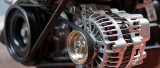
Generator device
The design of a car generator implies the presence of its own rectifier and control circuit. The generating part of the generator, using a stationary winding (stator), generates three-phase alternating current, which is then rectified by a series of six large diodes and the direct current charges the battery. Alternating current is induced by the rotating magnetic field of the winding (around the field winding or rotor). Next, the current is supplied to the electronic circuit through the brushes and slip rings.
Generator structure: 1.Nut. 2. Washer. 3.Pulley 4.Front cover. 5. Distance ring. 6.Rotor. 7.Stator. 8.Back cover. 9.Casing. 10. Gasket. 11.Protective sleeve. 12. Rectifier unit with capacitor. 13.Latch holder with voltage regulator.
The generator is located at the front of the car engine and is started using the crankshaft. The connection diagram and operating principle of a car generator are the same for any car. There are, of course, some differences, but they are usually associated with the quality of the manufactured product, the power and the layout of the components in the motor. All modern cars are equipped with alternating current generator sets, which include not only the generator itself, but also a voltage regulator. The regulator equally distributes the current in the excitation winding, and it is due to this that the power of the generator set itself fluctuates at a time when the voltage at the power output terminals remains unchanged.
Simple electromagnet and field concentration
If the rotor coil is wound with a non-iron core as shown in Fig. 3.13(a) , then you get a magnet with one pair of poles N ( North - northern) and S ( South - southern).
Rice.
3.13(a). A simple electromagnet. Due to the large distance between the poles, the magnetic field lines will be highly scattered in space. Now let's stretch the poles of the magnet towards each other, so that there is only a small gap between them (see Fig. 3.13 ( b )).
Rice. 3.13(6). Let's bend the ends of the electromagnet to concentrate the field.
And finally, let's make the poles of the magnet in the form of a set of teeth that fit into each other, but without touching (see Fig. 3.14 ). We will get in total a long narrow gap between the poles N and S , through which the magnetic field will “leak” outward. When the rotor rotates, this “leakage” will cross the stator windings and induce an emf in them.
How does he work
First, let's figure out how this device functions. His work scheme is as follows:
- The key is inserted into the ignition switch;
- The current goes to the excitation wires;
- The magnetic field created by the armature passes through the stator windings, and voltage appears at its terminals;
- When the armature rotation frequency becomes high enough, the self-excitation mode begins;
- The rectifier unit provided by the car design converts alternating current into direct current;
- The voltage regulator starts working when the crankshaft rotation speed changes, and the time for which the excitation wire is activated is adjusted.
The presented video will allow you to clearly get acquainted with the principle of operation of the generator.
Beginners are very interested in the most important question, without which there is no point in trying to fix something on their own - what is the generator used for.
First of all, the generator’s task is to provide energy to all electrically dependent equipment.
The mistake many people make is that the equipment is powered by a battery. The battery is needed to maintain the functionality of the devices when the engine is turned off. It powers the audio system, alarm system, etc.
When the engine is started with the help of the battery, all the reins of power pass to the generator. He is now responsible for the operation of the audio system, air conditioning, power windows, etc.
The second, but no less important task of the battery is to recharge the battery. This happens when the engine is running. If it were not for the generator, the battery would not be able to provide power to all consumers for a long time; it would have to be charged regularly in the garage.
Thyristor independent excitation systems (STN)
Independent thyristor systems (STN) are designed to power the excitation windings of large turbo and hydrogen generators with rectified controlled current, used in generating electricity at hydroelectric power stations and other generating stations - Fig. 5.2.
Abrahamyan Evgeniy Pavlovich
Associate Professor, Department of Electrical Engineering, St. Petersburg State Polytechnic University
Unlike self-excitation systems (SES), in STN the thyristor rectifiers of the main generator receive power from an independent power frequency AC voltage source - from an auxiliary synchronous generator rotating on the same shaft as the main generator
Fig.5.2. An independent thyristor system (STI) with an AC exciter and two groups of thyristors, in combination with a backup excitation circuit from a two-machine unit - an asynchronous motor-DC exciter. B – exciter (auxiliary generator) of alternating current, OVV excitation winding of the exciter, VRG, VFG – thyristor valves of the working and forcing groups, VVV – thyristor valves of the exciter rectifier, SUVRG, SUVFG, SUVVV – control systems for the valves of the corresponding groups, VTV – exciter rectifier transformer , TSNV – transformer MV of thyristor rectifiers.
The auxiliary excitation alternating current generator is built according to a self-excitation circuit. STN has an important advantage - its parameters do not depend on the processes occurring in the power system.
Vasiliev Dmitry Petrovich
Professor of Electrical Engineering, St. Petersburg State Polytechnic University
Thanks to the presence of an auxiliary generator, the excitation remains independent of the duration and distance of the short circuit and other disturbances in the power system, and the high rate of increase in the excitation voltage: no more than 25 ms until the maximum value is reached when the positive sequence voltage at the control point decreases by 5%.
The STN system ensures rapid de-excitation by changing the polarity of the excitation voltage: the de-excitation time from the maximum positive to the negative minimum excitation voltage does not exceed 100 ms.
Fig.5.3. Thyristor self-excitation system (STS) with a rectifier transformer (VT) and two groups of thyristors. TSNR, TSNF – transformers MV of thyristor rectifiers of working and forcing groups.
In the STN system, the rectified rated voltage can be 700 V, and the rectified rated current can be up to 5500A. The forcing multiplicity in voltage and current is at least two units, and the forcing duration is from 20 to 50 s. The accuracy of maintaining the generator voltage is no worse than ±0.5% and up to ±1%. The cooling system of the thyristor rectifier in the STN and STS systems can be forced air, natural air or water.