Self-excitation of a parallel excitation generator
Self-excitation of the parallel excitation generator occurs when the following conditions are met: 1) the presence of residual magnetic flux of the poles; 2) correct connection of the ends of the field winding or the correct direction of rotation. In addition, the resistance of the excitation circuit Rв at a given rotation speed n must be below a certain critical value, or the rotation speed at a given Rв must be higher than a certain critical value.
For self-excitation, it is enough that the residual flow is 2 - 3% of the nominal one. A residual flow of this value is almost always present in a machine that has already been running. A newly manufactured machine or a machine that has become demagnetized for some reason must be magnetized by passing current from an external source through the field winding.
If the necessary conditions are met, the self-excitation process proceeds as follows. A small electromotive force (emf), induced in the armature by the residual magnetic flux, causes a small current iв in the field winding. This current causes an increase in the flux of poles, and therefore an increase in e. d.s., which causes a further increase in iв, and so on. This avalanche-like self-excitation process continues until the generator voltage reaches a steady value.
If the connection of the ends of the field winding or the direction of rotation is incorrect, then a current i in the opposite direction occurs, causing a weakening of the residual flux and a decrease in e. d.s., as a result of which self-excitation is impossible. Then it is necessary to switch the ends of the field winding or change the direction of rotation. You can verify that these conditions are met by monitoring the armature voltage with a voltmeter with a small measurement limit when closing and opening the excitation circuit.
The polarity of the generator terminals during self-excitation is determined by the polarity of the residual flow. If, for a given direction of rotation, the polarity of the generator needs to be changed, then the machine should be remagnetized by supplying current to the field winding from an external source.
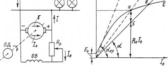
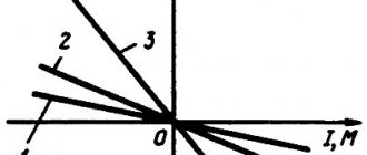
Figure 1. Self-excitation of a parallel excitation generator at different excitation circuit resistances (a) and at different rotation speeds (b)
Let's take a closer look at the process of self-excitation at idle. In Figure 1, a, curve 1 represents the idle speed characteristic (x. x. x.), and straight line 2 is the so-called excitation circuit characteristic or the dependence Uв = Rв × iв, where Rв = const is the resistance of the excitation circuit, including the resistance of the adjusting rheostat.
During the process of self-excitation iв ≠ const and the voltage at the ends of the excitation circuit
where Lв is the inductance of the excitation circuit.
Armature voltage at no-load (I = 0)
Uа = Eа – iв × Rа
is depicted in Figure 1, and curve 1. Since the current iв is small, then practically Ua = Ea.
But in a parallel excitation generator (see Figure 1, b, in the article “General information about direct current generators”) Uа = Uв. Therefore, the difference between the ordinates of curve 1 and straight line 2 in Figure 1, a is d(Lвiв)/dt and characterizes the speed and direction of change of iв. If line 2 passes below curve 1, then
iв grows and the machine self-excites to the voltage corresponding in Figure 1, and the point of intersection of curve 1 and straight line 2, at which
and the growth of iв therefore stops.
From an examination of Figure 1, a, it follows that the increase in iв and, therefore, Ua occurs slowly at first, then accelerates and slows down again towards the end of the process. The self-excitation process that has begun stops or is limited at point a' due to the curvilinearity of x. X. X. In the absence of saturation, Ua would theoretically increase to Ua = ∞.
In general, any self-excitation processes - electrical, and others, observed in various devices - are limited only by the nonlinearity of the system characteristics.
| Figure 2. Magnetic saturation bridges in a magnetic circuit |
If Rв is increased, then instead of straight line 2 we get straight line 3 (Figure 1, a). In this case, the self-excitation process slows down and the machine voltage, determined by point a'', will be less. With a further increase in Rv, we obtain straight line 4, tangent to curve 1. In this case, the machine will be on the verge of self-excitation: with small changes in n or Rv (for example, due to heating), the machine can develop a small voltage or lose it. The value of Rв, corresponding to line 4, is called the critical resistance of the excitation circuit (Rв.кр). When Rв > Rв.кр (straight line 5), self-excitation is impossible and the machine voltage is determined by the residual flux.
From the above it follows that the parallel excitation generator can only operate if there is a certain saturation of the magnetic circuit. By changing Rв you can adjust U to the value U = Umin, corresponding to the beginning of the knee of the x curve. X. X. In conventional machines Umin. = (0.65 – 0.75)Un.
E.m.f. Ea ∼ n, and for different values n1 > n2 > n3 we obtain x. X. x., shown in Figure 1, b by curves 1, 2, 3. From this figure it is clear that with a small value of Rв in the case of curve 1 there is stable self-excitation, with curve 2 the machine is on the verge of self-excitation and with curve 3 self-excitation is impossible. Therefore, for each given value of Rв there is such a value of rotation speed n = ncr. (curve 2 in Figure 1, b), below which self-excitation is impossible. This value is n = ncr. called the critical rotation speed .
| Figure 3. Parallel excitation generator no-load characteristics |
In some cases, it is required that U of the parallel excitation generator can be adjusted within wide limits, for example Un: Umin. = 5 : 1 or even U : Umin. = 10:1 (synchronous machine exciters). Then the curve x. X. X. should be bent already in its initial part. For this purpose, if necessary, sections with a weakened cross-section (magnetic saturation bridges) are made in the magnetic circuit in the form of slots in the sheets of the pole cores (Figure 2, a), protrusions in the upper part of these sheets (Figure 2, b) and the like. In such bridges, the magnetic flux is concentrated, and their saturation occurs even at low fluxes.
How to excite a generator
What is required to excite the generator? As mentioned earlier, the first step is to remove the “chocolate”, since the cause of the breakdown lies in it. Then the positive contacts on both devices are connected, and the negative ones in the regulator are cut and connected to the “ground” of the brushes.
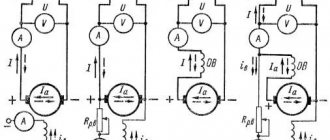
Insulate the wire at terminal “30” of the generator. Connect an indicator of at least 15 watts to output circuit “15”. This applies to generators of the G222 series. On other models of units, excitation is carried out by connecting to terminal “B”.
Generator self-excitation circuit.
The diagram shows diodes that are found only on modern types of generators; they are not present on earlier versions. It would be more correct to say that a circuit that does not have these diodes is classic, but one with them is newer.
Some generator models have armature brushes in their design. They also need to be removed and the tablet drilled out. One of the contacts is connected to the plus of the armature through a diode, the second - to the minus.
The current does not begin to flow immediately, but only after reaching a certain number of revolutions. Based on the tachometer readings, it can be determined that the feed will start only after 4 thousand revolutions per minute. That is, if we accelerate the engine to 4,000, the voltage appears, and if we reduce the speed to 1,000, the voltage will disappear. This is the principle of current generation during self-excitation.
Some car brands have a low-speed power plant. In this case, to increase the initial rotation speed, you will have to do something to the pulley. There shouldn't be any problems with regular engines.
Let's look further. It is important to know that at the output of the generator we will not receive 12 V. In the absence of a regulator (tablet), the unit will produce everything it can, depending on the speed, at times even up to 30 V. For example, at start this figure jumps to 36 V. You can see this by connecting the lamp to the appropriate voltage at the generator output. And then it gradually drops to 20 volts.
Of course, the scheme can be improved. For example, by adding a capacitor to the positive wire going to the armature. This is necessary so that when the engine speed decreases, the voltage does not drop. A high-quality capacitor will also be useful at the output; this will smooth out the first voltage surge and regulate subsequent dips.
When assembling such a circuit, it is worth remembering about the output of high voltage. It is significantly higher than the normal 12 V, so there is a danger of burning out the light bulb, ECU and other electronics of the car.
Remember! When operating from self-excitation, the generator will transmit all the released electricity that it can generate, and this can cause severe overheating of the unit itself. A slight overload and you can go for a new unit. Accordingly, it is recommended to use this method only in cases of extreme necessity.
Short circuit characteristic
The short circuit characteristic I = f(iв) at U = 0 and n = const for a parallel excitation generator can only be removed when the excitation winding is powered from an external source, as for an independent excitation generator, since during self-excitation at U = 0 the circuit current excitation is also zero iв = 0.
External characteristics
The external characteristic U = f(I) of the parallel excitation generator is removed at Rв = const and n = const, that is, without regulation in the excitation circuit, under natural operating conditions. As a result, to the two reasons for the voltage drop indicated for the independent excitation generator (see the article “Independent Excitation Generators”), a third is added - a decrease in iв with a decrease in U. As a result, the external characteristic of the parallel excitation generator (Figure 4, curve 1) drops steeper than at the independent excitation generator (curve 2). Therefore, the nominal voltage change (see the definition in the article “Independent Excitation Generators”) for the parallel excitation generator is greater and is delta Un% = 10 – 20%.
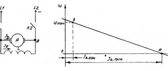
| Figure 4. External characteristics of parallel (1) and independent (2) excitation generators |
A characteristic feature of the external characteristic of the parallel excitation generator is that at a certain maximum current value I = Imax. (point a in Figure 4) it makes a loop and comes to point b on the abscissa axis, which corresponds to the steady-state short circuit current. Current Ik.set is relatively small and is determined by the residual flow, since in this case U = 0, and therefore iв = 0. This behavior of the characteristic is explained as follows. As the current I increases, the voltage U drops first slowly, and then faster, since with a decrease in U and iв the flux Фδ falls, the magnetic circuit becomes less saturated and small decreases in iв will cause increasingly large decreases in Фδ and U (see Figure 3). Point a in Figure 4 corresponds to the transition of the x curve. x.x. from the bottom of the knee to a straight, unsaturated area. At the same time, starting from point a (Figure 4), a further decrease in the load resistance Rng. connected to the terminals of the machine not only does not cause an increase in I, but on the contrary, a decrease in I occurs, since U falls faster than Rng..
The operation of the machine on the ab branch of the characteristic is somewhat unstable and there is a tendency to spontaneously change I. Current Ik.set. in some cases it may be more than In.
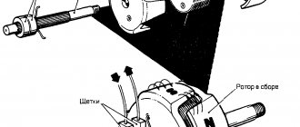
Construction of the external characteristic of the parallel excitation generator using x. X. X. and the characteristic triangle is shown in Figure 5, where 1 is the x curve. X. X.; 2 – characteristic of the excitation circuit Uв = Rв × iв at a given Rв = const and 3 – constructed curve of the external characteristic.
At I = 0, the value of U is determined by the intersection of curve 1 and line 2. To obtain the value of U at I = In, we place the characteristic triangle for the rated current so that its vertices a and b are located on curve 1 and line 2. Then point b will determine the desired value U, which can be proven using similar reasoning set out in the article “Generators of independent excitation”, in the case of constructing the external characteristic of an independent excitation generator. For other current values, between 1 and 2, it is possible to draw inclined straight segments parallel to a, which represent the hypotenuses of the new characteristic triangles. The lower points of these segments in', in'', etc. determine U at currents
By transferring all these points to the left quadrant of the diagram in Figure 5 and connecting them with a smooth curve, we obtain the desired characteristic 3. Taking into account the nonlinear dependence of the leg ab of the triangle on I, the experimental dependence U = f(I) has the character shown in Figure 5 on the left by the dashed line.
| Figure 5. Construction of the external characteristic of the parallel excitation generator using the no-load characteristic and the characteristic triangle |
Although the steady-state short-circuit current of a parallel excitation generator is small, a sudden short circuit at the terminals of this generator is almost as dangerous as that of an independent excitation generator. This is explained by the fact that due to the high inductance of the excitation winding and the induction of eddy currents in massive parts of the magnetic circuit, the decrease in the magnetic flux of the poles occurs slowly. Therefore, the rapidly increasing armature current reaches the values Iк = (5 – 15)In.
Adjustment and load characteristics
The control characteristic iв = f(I) at U = const and n = const and the load characteristic U = f(iв) at I = const and n = const are removed in the same way as for the independent excitation generator. Since iв and Ra × iв are small, the voltage drop from iв in the armature circuit has practically no effect on the voltage at the generator terminals. Therefore, the indicated characteristics are almost the same as those of the independent excitation generator. Constructing these characteristics using x. X. X. and the characteristic triangle are also produced in a similar way.
In conclusion, it can be noted that the characteristics and properties of independent and parallel excitation generators differ little from each other. The only noticeable difference is a slight discrepancy in external characteristics ranging from I = 0 to I = In. The greater discrepancy between these characteristics when I is much larger than In does not matter, since machines, as a rule, do not operate in such operating conditions.
Source: Woldek A.I., “Electrical machines. Textbook for technical schools" - 3rd edition, revised - Leningrad: Energy, 1978 - 832 p.
Basic generator malfunctions
Let's look at the most common malfunctions typical of a car generator:
- Electrical circuit breaks, short circuits and other damage. To diagnose such a defect, it is necessary to check the current strength and voltage indicator at the output contacts of the unit. Based on the information received, a decision is made on further actions.
- Motorists also often encounter problems such as excessively worn graphite brushes, a voltage regulator, or a diode bridge. Any worn or failed part should be replaced with a new one. As for the regulator, as mentioned above, it ensures optimal recharging of the car battery based on the temperature in the engine compartment. In other words, the device automatically determines the required voltage for the battery under given conditions. Some generator models feature manual switching of modes depending on the time of year. In this case, low temperatures will not have a negative effect on the operation of the device. The failure of the relay will be signaled by voltage drops in the system - this could be a weak light from the headlights while driving, which light up brighter as the engine speed increases.
- Faulty bearings. If this element breaks down, extraneous increased noise will appear, although the same symptom is also observed if the unit is poorly lubricated.
- Noises and howls. If such signs are detected, it is necessary to check the separator elements, raceways, and slip rings for rotation. Such symptoms may also indicate the possible occurrence of an interturn short circuit in the winding of the stator element or traction relay. In any case, if extraneous noise is detected during operation of the generator, it is recommended to conduct a thorough diagnosis of the condition of the contacts.
- The operating temperature of the generator can sometimes reach 90 C, however, in case of obvious overheating, it is necessary to immediately check the functionality of the diode bridge. In addition, you should determine whether the vehicle’s on-board network is overloaded with additional devices and third-party devices. In the event of a critical increase in temperature, the first thing that will happen is that the insulation of the stator winding will darken; in the worst case, it may even melt.
- Severe wear on the alternator belt. If excessive wear occurs, the unit belt may simply break, which leads to its overall malfunction. That is, in this case, all consumers will consume electricity from the car’s battery. If the belt breaks, the generator stops performing its functions, which means the driver has very little time to get to the nearest car service center or service station. Such a defect can be indicated by voltage drops in the on-board network of the machine. In this case, you should check the belt for integrity, carefully inspect its surface for cracks, tears, delaminations and other mechanical damage. If they are found, it is recommended to replace it immediately.
If any defect is discovered, it is better to immediately fix it yourself or contact a car service. Otherwise, you risk facing more expensive repairs.