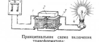
Step-down voltage transformers are required, and sometimes irreplaceable, in conditions where there is a risk of electric shocks due to an unfavorable environment, for example, in damp rooms. In such situations, models of the indicated devices are used, including 36 Volt ones. This way, if there is contact with the electrical network, the shock will be minor, and it is less likely to damage other devices. There are ready-made modules - YTP (box with a step-down transformer, details later in the article) - for which you do not need to deal with contacts. But the 220/36 V step-down transformer (VT) itself is a device that cannot be immediately plugged into an outlet without preparation; you need to know how to connect it to the wiring. Let's consider the rules, connection options, preparatory steps, and warnings.
Connection features
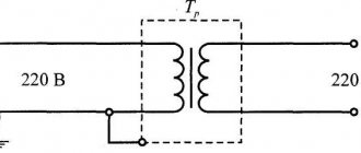
Let's look at the basics of how to calculate and connect a step-down transformer 220 36
It is important to connect to the coils of the device in strict accordance with their purpose, taking into account the needs of a specific situation. Depending on where the load is connected and 220 V, the device will be either a step-down or a step-up
And incorrect connection of the winding contacts will lead to rapid failure of the voltage transformer (overheating, short circuit).
The VT is connected in parallel with the load, its purpose is to transform the input voltage with a certain ratio, which, if simplified, is equal to the turns ratio. When their number in a primary (network) is less than in a secondary, then the output value decreases. The step-up voltage transformer has the opposite - there are more turns of the secondary (load coil). It should be noted that when the load increases, the coefficient. the ratio decreases, which is also affected by the cross-section of the winding wires.
For complex products, the number of coils exceeds 2, each with its own coefficient. transformations, some of them decrease, some increase. Any transformer can operate in reverse mode: when an alternating voltage is applied to the load winding, we obtain it at the output of the primary with the same conversion coefficient.
Features of transformers for halogen lamps
To properly control the operation of a halogen lighting device, be sure to use a transformer that reduces the output voltage to 12 volts. Thanks to this, the lamps are protected from overvoltage and power surges.
Such converters normalize incoming electricity and output the required voltage level from 6 to 24 volts, depending on the halogen lamp used. Today, there are two main types of step-down transformers, depending on the design of the device:
- toroidal winding converters;
- electronic or pulse step-down transformers.
Standard winding transformers are considered the most affordable and easiest to operate, and also have good power performance. It is easy to connect a halogen light source to such a device.
The operating principle of such a converter is based on the electromagnetic interconnection of the device coils. But due to the use of the latter, such a transformer has serious disadvantages - heavy weight, reaching several kilograms, and dimensions that take up a lot of space. It is for this reason that such voltage-reducing devices are not widely used in everyday life.
Plus, the electromagnetic converting device gets very hot during operation, which can negatively affect halogen lamps. In addition, overheating of toroidal winding transformers can lead to voltage surges in the house, thereby adversely affecting other household devices.
In turn, low-voltage pulse converters, which are also called electronic transformers, have received the widest possible range of applications both in everyday life and in production. This popularity is primarily due to the low weight and dimensions of the device. In addition, such a device qualitatively reduces the voltage without heating up during operation. The only disadvantage of such a transformer for 12-volt halogen lamps is the fairly high cost of the device.
Recently, pulsed step-down transformers have appeared on the electronics market, which, even at the production stage, are equipped with built-in protection against short circuits and overvoltage, which significantly extends the service life of both the converter and light sources.
Such electronic converters are often used for mounting halogen light sources in the furniture industry or suspended ceilings. According to the principle of operation, such a transformer will differ from its winding analogue in that energy conversion is achieved through semiconductor devices and electronic spare parts.
Features of business development in China
As we have already said, Dima started his business in China during his student years. It started with minor sales of Chinese products: sneakers, auto parts..., but it was not always accompanied by luck.
It happened that there was no way to make a profit. All this happened due to problems with logistics in our country. The deadlines were running out, so it was necessary to sell the goods at a loss.
Dmitry really didn’t like this, so he decided that it was much better not to be a reseller, but to create a logistics company on his own. In his opinion, it should function efficiently and quickly deliver Chinese goods for small organizations.
Dmitry Portnyagin claims that he was the first who, when creating a company, relied specifically on the Internet. He never attended exhibitions, presentations, or held business meetings with potential clients, as others had done for many years. He simply created contextual advertising.
The business grew quickly, so Dima had to quit studying at the academy in his second year. However, in 2008, an economic crisis occurred in the world, and therefore Dmitry Portnyagin had to move to China. After all, all his clients were either in the capital of Russia or in its central part.
The only correct solution that Dmitry saw was to move to Guangzhou. It was there that the logistics company (Transit Plus) was registered.
First TransitPlus office
What can 12 or 24 volt voltage be used for in everyday life?
In domestic environments, low voltage power supplies are often used. Portable/stationary electrical and electronic devices, as well as some lighting devices, are powered from 12 or 24V DC voltage:
- cordless electric drills, screwdrivers and electric saws;
- stationary pumps for watering gardens;
- audio-video equipment and radio-electronic equipment;
- video surveillance and alarm systems;
- battery-powered radios and players;
- laptops (netbooks) and tablets;
- halogen and LED lamps, LED strips;
- portable ultraviolet irradiators and portable medical equipment;
- soldering stations and electric soldering irons;
- chargers for mobile phones and power banks;
- low-current power supply networks in places with high humidity and landscape lighting systems;
- children's toys, Christmas tree garlands, aquarium pumps;
- various homemade radio-electronic devices, including those based on the popular Arduino platform.
Most devices run on batteries and Li-ion batteries, but the use of commodity items is not always justified in terms of operating costs. Batteries can be charged 300–1500 times, but galvanic cells with high energy capacity and low self-discharge current are expensive. It will be noticeably cheaper to purchase batteries, especially salt and alkaline ones, but such elements will have to be changed frequently. Moreover, to provide a supply voltage of 12 V, you will need 8 series-connected AA or AAA batteries or 1.5-volt “tablets” in a 27A housing.
Therefore, in places with access to a 220 V 50 Hz household network, it is more rational to use a power supply to power electrical receivers with an amperage of more than 0.1 A.
Selecting a ready-made solution
Today, a transformer with any parameters can be found in radio electronics or welding equipment stores. Along with traditional ones, new generation devices are also sold - inverter transformers. In such devices, the current first passes through a rectifier before entering the primary winding.
And then - through an inverter assembled on the basis of a microcircuit and a pair of key transistors, which again turns the current into alternating current, but with a much higher frequency: 60 - 80 kHz instead of 50 Hz. This conversion of the input current makes it possible to significantly reduce the size of the transformer and greatly reduce losses.
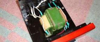
Box with step-down transformer YaTP 0.25
The transformer should be selected according to the following characteristics:
Input voltage and current frequency: the characteristics of the device must indicate “220 V” or “380 V” if it is purchased for a 3-phase network. The frequency should be 50 Hz. There are transformers that are designed, for example, for a frequency of 400 Hz or more - if connected directly to a household power supply, such a device will burn out.
Voltage and type of current at the output: everything is clear with the output voltage - it must correspond to the voltage for which the electrical consumer is designed
But at the same time, it is important not to forget to look at what current the transformer produces. Many of them today are equipped with rectifiers, as a result of which the output current is not alternating, but direct.
Rated power: it is very important that the maximum power with which the transformer can operate (this is called the rated power) is approximately 20% greater than the load power
If this reserve is not there, and even more so if the rated power of the transformer is less than the power consumed by the load, the converter windings will overheat and burn out.
- Open: equipped with a non-sealed casing, into which moisture and dust can enter. But there is the possibility of forced cooling using a fan.
- Closed: equipped with a sealed housing with a high degree of moisture and dust protection, so they can be installed in rooms with high humidity.
Models with an aluminum body can be used in outdoor conditions (street lighting with LED lamps, advertising). Due to the inability to apply forced cooling, the power of closed transformers is limited.
Transformers are also:
- rod: coils can only be placed in a vertical position;
- armored: work in any position.
The cost of transformers varies greatly and primarily depends on the power. Here are some examples:
- YaTP-0.25. A device with a rated power of 250 W, equipped with a housing. The cost is 1700 rubles.
- OSM-1-04. Can operate with an input voltage of 220 V or 100 - 127 V, the output is 12 V. There is no housing. Cost - 2600 rubles.
- OSZ-1 U2 220/12. Transformer 1 kW. Costs 5300 rubles.
- TSZI-4.0. Converter with housing, rated power is 4 kW. Input voltage - 220 or 380 V, output - 110V or 12 V. Cost - 10.5 thousand rubles.
Portable transformer in TSZI-2.5 kW housing. can be connected to both 220 V and 380 V, output - 12 V. Cost - 13.9 thousand rubles.
Erroneous designations
Erroneous connections occur when the rules for connecting the ends are not followed. This occurs as a result of incorrect winding or incorrect designation. As a result, when the device is connected to a three-phase network, the windings connected in opposite directions compensate each other’s magnetic fluxes, so a current begins to flow through them, limited only by the active resistance of the winding wire, which is equivalent to a short circuit.
To eliminate cases of incorrect switching, it is recommended that after repairing equipment or before switching on unknown devices, carefully check the phasing of each winding using several methods to eliminate possible errors.
A preliminary calculation of voltages for measurements using the voltmeter method will help reduce the likelihood of error. The data obtained serve as guide values that need to be taken into account when making subsequent measurements.
Transformer for a chandelier: selection criteria
When choosing such equipment, you should pay attention not only to the technical characteristics, but also to the possibility of placement. If you plan to install a stretch or suspended ceiling, there will be no questions
But in the absence of them, everything becomes a little more complicated. You can choose a fairly compact device that fits in a junction box, but it is worth considering that small dimensions also mean less power, which may not be enough if there are a lot of consumers. If the standard transformer in the chandelier fails, then everything is simple - we dismantle it and purchase an identical one. Now let’s look at what to do if you decide to change incandescent lamps to halogen or LED.
Let's consider the option. It is planned to install 8 halogen lamps with a power of 30 W each. Let's do the calculations: 8 × 30 + 10% = 264 W
Paying attention to the range of capacities offered by the manufacturer, you can see that the closest figure to the larger side is a 12 volt 300 watt transformer. This is exactly what you should purchase. Below you can see a diagram of an electronic transformer for 12 V halogen lamps
How much does it cost and where to buy a 220/12 Volt step-down transformer - price review
The price of 220 to 12 Volt transformers depends on their technical characteristics, purpose and degree of protection, as well as the place of their sale. These products can be purchased in lighting and electrical stores, retail chains of various equipment and building materials, as well as on the Internet.
In the departments of lighting and electrical products, step-down transformers of various brands and designs are always on sale
The following table shows the cost of various models of step-down transformers when selling them through Internet resources, as of the second quarter of 2022.
| Model | Specifications | Average cost (as of May 2022), rubles |
| TDM SQ0360-0011 | Electromagnetic 220/12V 35−105W | 529 |
| TDM SQ0360-0010 | Electromagnetic 220/12V 20−60W | 389 |
| YaTP-0.25 | Electromagnetic 0.25 kW, 220/12V, IP30 | 1500 |
| GALS ET-190K | Electronic 220/12V 105W | 550 |
| GALS ET-190T | Electronic 220/12V 250W | 1469 |
| SVETOZAR SV-44955 | Electronic 220/12V, 1 input−2 outputs | 215 |
| SVETOZAR SV-44965 | Electronic 220/12V 2 inputs-3 outputs | 649 |
| NT-EH-060-EN Navigator | Electronic 220−12V 60W | 200 |
| NT-EH-105-EN Navigator | Electronic 220−12V 105W | 270 |
transformer TDM SQ0360-0010
YaTP-0.25
GALS ET-190K
GALS ET-190T
NT-EH-060-EN Navigator
NT-EH-105-EN Navigator
The presence of various models that differ in technical characteristics, sizes and operating conditions allows you to select a step-down transformer in accordance with the requirements for it in different price ranges.
Nowadays, it is not difficult to buy a voltage converter; the main thing is to make the right choice from the variety of offers on the electrical products market
Is it useful to install an isolation transformer?
One transformer model OSM 220/220 replaces the ground loop, RCD and voltage relay. Even if a short circuit occurs, the wires do not heat up excessively, and the OSM simply “eats” voltage drops, providing reliable protection for fragile home equipment, such as a computer.
Figure 3: Isolation transformer model OCO
But there is one catch. It will not be possible to install one transformer for the entire apartment at once - they simply don’t produce such high power. Therefore, you will have to take several, which may exceed the price of installing additional switching elements in the electrical panel. And yet, installing OCM will save the user from installing grounding, which is considered a rather costly process.
Manufacturing of windings
The coil is placed on a wooden block with the dimensions of the magnetic core. A hole for the winding rod is pre-drilled in it. This part is inserted into the machine, and the winding manufacturing process begins:
- 2 layers of varnished fabric are wound on the reel;
- one end of the wire is fixed on the cheek and the handle of the machine begins to slowly rotate;
- the coils must be laid tightly, isolating each wound layer from the adjacent one with varnished cloth;
- after the primary winding coil is wound, the wire is cut and its second end is fixed on the cheek next to the first.
Insulating tubes are put on both terminals, and the outside of the winding is covered with insulation. The secondary winding coil is wound in the same sequence.
The concept of a group connecting the windings of a three-phase transformer
Three-phase networks use two types of connections: star and delta. When making structures, it may seem that there are only four types of winding arrangements:
- Star-star.
- Star-triangle.
- Triangle-star.
- Triangle-triangle.
In reality, everything is more complicated, since in each type of connection (star or triangle) the parts of the windings can be connected differently. An example is a conventional two-winding transformer. If such a device has the same beginnings and ends of the windings, then the phase shift will be equal to 0. Turning one of the windings will give a phase shift of 1800.
There are also z-shaped winding connections (zigzag). In such designs, each of the windings consists of two parts located on different cores of the transformer magnetic circuit.
A three-phase network is characterized by a phase shift relative to one another by 1200. Therefore, there are a total of 12 connection groups. Each group is characterized by a certain shift of the same phases at the input and output of the transformer.
Design, principle of operation
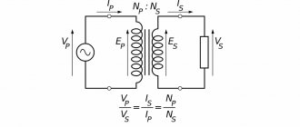
A standard step-down transformer consists of 2 windings (primary and secondary) wound on a ferrimagnetic core with copper wire. The primary is connected to the network, and the secondary to the load. The operating principle of such a device is as follows:
- The voltage applied to the primary winding generates an alternating field around the core.
- Magnetic induction, when connected to a load, creates a voltage in the turns of the secondary winding, and energy will flow from the primary winding and be transferred to the secondary circuit.
The output voltage is influenced by the ratio and number of turns of each winding. By adjusting this indicator, you can achieve any current value on the secondary winding, and get both a step-down and step-up transformer. It should be borne in mind that a device connected to a 220 V household network will produce alternating voltage, which can then be converted by a rectifier if necessary.
Currently, electronic-type step-down devices made on the basis of semiconductors, the operation of which is complemented by an integrated circuit, are widely used. They have certain advantages in the form of small size, high efficiency, light weight, lack of heating and noise, the ability to regulate current, and short circuit protection. But the traditional transformer continues to be actively used due to its reliability and simplicity of design.
General information
Voltage transformers, as a rule, are a type of transformer that are designed not to transmit power, but to galvanically separate the high-voltage side from the low-voltage side.
Such transformers are designed to power measuring and control devices. On the “high” side of various voltage transformers, naturally, the voltage can be different, it can be 6000, 35,000 volts and even much more, but on the “low” side (on the secondary winding) it does not exceed 100 volts.
This is very convenient for unifying control devices. If you make measuring and control devices, and these are mainly relays, for high voltage, then, firstly, they will be very large, and secondly, very dangerous to maintain.
The transformation ratio is indicated on the transformer itself and can look like Ku = 6000/100, or simply 35000/100. Dividing one number by another, we get in the first case this coefficient is 60, in the second 350.
These transformers are available as “dry” transformers, in which electrical cardboard is used as insulation. They are usually used for voltages up to 1000 volts. Example NOS-0.5. Where, H means voltage, meaning a voltage transformer, O - single-phase, C - dry, 0.5 - 500 volts (0.5 kV). And also oil ones: NTMI, NOM, 3NOM, NTMK, in which oil plays the role of both an insulator and a cooler. And cast, to be precise, with cast insulation (3NOL - three-winding single-phase voltage transformer with cast insulation), in which all windings and the magnetic circuit are filled with epoxy resin.
Connection
To connect a transformer, you need to connect a load to the contacts of the secondary winding, and then apply household voltage to the contacts of the primary coil.
The connection diagram to the secondary winding depends on what voltage needs to be obtained at the output: if 24 V, we connect to the outer terminals, if 12 V, to one of the outer terminals and the terminal from the 120th turn.
Connection diagram for 12V spotlights via a transformer
If the consumer operates on direct current, a rectifier must be connected to the terminals of the secondary coil. For this purpose, a diode bridge equipped with a capacitor is used (it acts as a filter, smoothing out ripples).
If there is electricity at the dacha, then there must be grounding. Grounding for a summer residence is an effective way to protect against electric shock.
We'll tell you how to check a capacitor with a multimeter below.
Video of transformer rewinding
Time of different stages of this video:
26 min 28 sec
- foil screen between primary and secondary
27 min 52 sec
- how to correctly connect the windings in series
36 min 43 sec
- how to find out the direction of turns using a battery and a multimeter
44 min 14 sec
- calculation and winding of a new secondary winding
1 hour 24 minutes 20 seconds
— mains voltage sag and other losses
1 h 30 min 01 sec
— no-load current
1 hour 32 minutes 14 seconds
- aluminum soldering
1 hour 33 minutes 42 seconds
- result
Scope of application of transformers
Current transformers are installed in many household electrical appliances and industrial electrical equipment that require higher or lower voltages than 220 V or 380 V. To power halogen lamps, a voltage of 12 V is required, that is, almost 20 times lower than the mains, and TT reduces it to the required value.
Transformers are also used for electricity metering. Measuring CTs are widely used, which are connected to measuring instruments (voltmeters, ammeters, etc.) and transmit currents to them. Both compact models are produced that fit into the housing of household appliances, and models for installation outdoors on power lines.
Examination
If the transformation ratio is known, then using a voltmeter you can determine the number of the main connection group. For this purpose, voltage is applied to ends A and a or x and y and the voltages are measured at terminals B-c and C-c when connected in a star, or By and Cz when connected in a triangle. The following ratios are used for verification:
UBb = UCc = UAa(k-1) Group Y/Y-0
UBy = UCz = Uxy(k+1) Y/Y-6
UBb = UCc = UAa(√(1-√3k+k2)) Y/∆-11
UBy = UCz = Uxy(√(1+√3k+k2)) Y/∆-5
To avoid equipment damage, emergency situations and injury, all measurements should be made at low voltage, without connecting the equipment to the main network of the enterprise.
Operating principle
To understand the principle of operation of the power supply, it is necessary to consider the block diagram (Fig. 1). It consists of:
- Network rectifier (SV). Transforms alternating current into direct current. Thus, it ensures smoothing of voltage pulses.
- High frequency converter (HFC). Its main task is to convert DC voltage into AC voltage. Wherein:
- a rectangular pulse shape is formed;
- the required signal amplitude can be achieved.
- Element for voltage rectification (VR). Performs voltage smoothing. In some types of circuits, this block is absent, thereby allowing electric current to flow to the smoothing element connected by the load section of the circuit.
- System control unit (SU). With the correct assembly of such a circuit for a 12V power source, you can obtain a fairly high efficiency, about 80-95%.
Symbols and explanation
Groups are marked with numbers from 0 to 11. For convenience and standardization, the following is accepted:
- connections of the same type (∆/∆, Y/Y) have even numbers;
- heterogeneous connections (∆/Y, Y/∆) – odd.
Three-phase transformers are made on core magnetic cores. Each phase is located on a separate rod. This greatly simplifies further work and coordination of devices with each other.
If a transformer has identical phases wound on the same rods, then the groups of connections are called main (0, 6, 11, 5). The remaining groups are derivatives.
Since the minimum phase shift can be 300, the number of options is 12, which corresponds to the positions of the clock hands. The 0th and 12th positions are the same. Based on this, they say that the group number coincides with the position of the hour and minute hands. The phase shift is calculated simply:
Group number*300.
The following designations are accepted on electrical circuits and devices:
- Y, U – star;
- Yn, Un – star on the low voltage side;
- Yo, Uo – star with zero point;
- ∆, D, D – triangle;
- ∆н, Дн, Dн – triangle on the low voltage side.
An example of marking a two-winding transformer:
- ∆/Yн – 11. Primary winding triangle, secondary (step-down) star. Phase shift 3300;
- Y/Yо -0. Both windings are connected in a star, the secondary with the zero point removed. There is no phase shift.
Also on electrical diagrams, high voltage (HV) windings are designated by the following symbols:
- A, B, C – beginning of the winding;
- X, Y, Z – end of the winding.
Likewise for the low voltage side:
- a, b, c;
- x, y, z.
Multi-winding devices are marked in a similar way, for example:
Yo/Y/∆ – 0 – 11.
Instead of the zero group, the twelfth group can be indicated, which is completely equivalent.
We assemble with our own hands
A do-it-yourself converter can be a solution to some problems. For example, if for garage work you need to connect equipment with a 220 V power supply, but the network has a voltage of only 36 V, then a self-assembled step-up transformer will solve this problem.
Types of converters 12 to 220 volts
Inverters are devices that allow you to convert direct current values, including 12 V, into alternating current with or without changing the voltage level. Current DC voltage converters currently produced can be represented by:
- voltage regulators;
- voltage level converters;
- linear stabilizers.
As a rule, such devices are generators of periodic voltage close to the shape of a sinusoid.
Converter circuit 12 to 220 volts.
How to connect a step-down transformer 220/12V
There is a certain procedure for connecting a step-down transformer. First, consumers are connected to the secondary winding, and only then voltage is applied to the primary winding. Installation is carried out according to the diagram contained in the technical documentation. Grounding can be connected in various ways. If the device case is metal, then it can also be grounded. Below are photos of various types of transformers.
Very important! All work related to electrical installation is carried out exclusively with the voltage removed. Remember that electric shock is dangerous to life and health.
If you plan to connect LED lamps, then you need to purchase a transformer with a built-in rectifier or separately include a diode bridge in the circuit, which will provide the constant voltage necessary for stable operation of the light diodes.
Types and classifications
Main classifications of transformers:
- By number of phases.
- Based on the presence or absence of grounding of the output,
- According to the principle of action.
- According to the number of stages of transformation.
- By the presence of a compensation winding or a winding for monitoring network insulation.
- By type of insulation:
- According to design features.
Old 3-phase oil transformer
Installation location:
- outdoor,
- internal,
- built into the power transformer,
- installation as a separate element.
The main features of transformers and their designations are given in the table:
A three-winding transformer should be made with two secondary windings:
- basic,
- additional.
How to choose materials
When making a step-down transformer from 220 to 12 Volts, it is important to use high-quality materials - this will ensure high reliability of the device that you will subsequently assemble on it. It should be noted that the transformer allows for decoupling from the network, so it can be installed to power incandescent lamps and other devices that are located in rooms with high humidity (showers, basements, etc.)
d.). When making your own coil frame, you need to use durable cardboard or textolite.
It is recommended to use domestically produced wires; they are much stronger than their Chinese counterparts and have better insulation. You can use wire from old transformers, as long as there is no damage to the insulation. To isolate the layers from each other, you can use either plain paper (preferably thin) or FUM tape, which is used in plumbing. But to insulate the windings, it is recommended to use fabric impregnated with varnish. It is necessary to apply insulation on top of the windings - varnish cloth or cable paper.
What will be needed?
Measuring winding voltage
To carry out all the work yourself you will need:
– the transformer itself;
– voltmeter;
– power cable (for example, this https://provod-kabel.kiev.ua/);
– appropriate tools.
Naturally, you also need to have some knowledge and skills to avoid mistakes.
How to choose a step-down transformer
Imported electrical appliances operating on a 110-volt network have become available for sale. Domestic electrical networks supply current with a voltage of 220 volts. Using a foreign household or other purpose device is problematic. But there is a way out. You can purchase a 220 transformer with step-down terminals for 110 volts.
When choosing a lowering product, it is important to calculate the maximum load for which it is designed. The result is obtained by the following method
Multiply volts by current to get power. The formula looks like this: V x A=W. Select a powerful consumer of electrical energy, calculate the peak load using the formula, add 20% to its value.
Let's give an example. A housewife purchased an imported food processor operating on a 110-volt network, designed for a current of 3 A. Let’s multiply the indicators. We get a power of 330 W. This is the standard power at which the combine operates. But while preparing a dressing, for example for borscht, a bone got into the processor, which the device should grind. In a second, the power will jump to 1400 W. The manufacturer of electrical appliances indicates the maximum power in the technical data sheet.
It is not difficult to make a device that reduces the current yourself. The algorithm of actions is as follows: count the number of turns of metal wire on the coils. The primary calculation begins with a 220 volt winding. After calculations, the number of turns is determined. 2200 turns are obtained with a wire cross-section of 0.3 mm and a rod area of 6 square meters. cm.
Then calculate the number of turns for a 12 volt coil. The second coil, producing a voltage of 12 volts, will have 120 turns with a wire cross-section of 1 mm. The number of turns of one winding should not be equal to the other. Ideally, they can if the copper wire is of different sections.
A voltage of twelve volts powers LED strips, lamps, and halogen lighting. Halogen lamps require little power. An important point is the manufacture of the core. The power of the transformer depends on its quality.
If there is no special electrical steel at hand, use metal containers for beer, bread kvass, and other liquid products. Strips 3 dm long and 0.2 dm wide are cut from the cans. The workpieces are fired, and then the scale deposits are removed. They are varnished and wrapped in paper on one side.
The second winding is filled with wires with a cross section of 1 mm. The reel base is made of high-strength cardboard material. Wrap the cardboard blank in paraffin-impregnated paper. Wire is wound onto the prepared cores, not forgetting to separate the wound turns with paper. Ready-to-use windings are mounted on a compact wooden or metal frame. Secure with staples or other fasteners.
Transformation of Roma
The Transformer team is constantly experimenting with content. In one of the episodes, Dima met Roman. Roma worked as a hired worker his entire adult life.
During the conversation, Dima asked Roma why he didn’t start his own business. Roma replied that the main reason is fear due to uncertainty. In business, no one can guarantee your success!
As a result, after some thought, Roma decided to quit his job and start his own business under the supervision of Dmitry. Roma took out a loan in the amount of 3,220,000 rubles and is preparing to open the first grilled chicken outlet on the market under the new brand “Kurochka”. What will come of this - only time will tell. Many believe in Roma, but there are also those who say that he will burn out.
Dima holds Roma's resignation letter in his hands
Now there is very high attention to this experiment among subscribers; everyone wants to see the launch of a business from scratch in real time. For this purpose, an additional section may appear on the channel.
In 2022, the Chicken project was closed.
How to connect a step-down transformer
Preparatory stages:
- Make sure that the device used is a voltage transformer (there are also current ones). To connect the load, you need to choose a coil with the highest number of turns and resistance.
- Anode-filament versions of devices have windings of all types. You can recognize the primary by looking at its conclusions - they are usually at a distance from the rest. Sometimes such turns are isolated in another segment of the frame, then it is even easier to recognize it. There are also many thematic forums on the Internet, so it won’t be difficult to clarify the device parameters there and where the output is.
- Be sure to check the voltage value and the frequency of the VT - it should be 220 V and 50 Hz.
- Sometimes the network winding has 3 terminals, one of them is for a 110 or 127 V network. Our goal is to combine them so that the resistance is maximum, and it is to them that 220 V must be supplied.
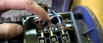
- If there are not 3, but 4 inputs, then this is a model with 2 coils, which are connected by a jumper from the wiring in series, in phase. First, they do it, then the windings are connected to a voltmeter with a limit of 500 V. Next, several Volts are given to one of the load windings (you can use a battery). Do not touch the terminals of the network turns while doing this.
- Record the results of the tester, turn it off, swap the leads of any of the first coil, and repeat the process.
- Choose the option with the highest value.
If there is only one winding, it is advisable to connect it to the network through a fuse. The current rating is selected for the transformer - no more than 0.05 A per 10 W.
Connection procedure
The activation itself is simple. It is enough to remember the main rules:
- A load is connected to the contacts of the secondary coil, then 220 V is supplied to the primary. For this purpose, the device can be connected directly to the wiring (twisted, terminals), including directly in the panel, or its terminals can be equipped with a cord with a plug to a 220 V socket and an external socket for connected devices.
- The load goes to the winding with high resistance.
The main thing in connection is not to confuse the windings and terminals, take into account the operating principle of a step-down transformer 12, 24, 36 V: the load goes to the secondary and if it has several contacts, then at the output you can get a different voltage, for example, not 36, but 24 V. Therefore, a check with a voltmeter or multimeter is required, as described in the previous section.
A clear example with illustrations
Diagram of a conventional transformer:
The input is the primary, 220 V is supplied there. As can be seen in the diagram, some VTs have outputs for 110 V. 36 V or another reduced voltage is removed from the output.
Consumers powered by direct current must have a rectifier, a diode bridge, etc. - this will already be a power supply; this is not necessary for incandescent lamps.
The calculation must take into account that some transformers have two separate output windings that need to be connected by an external wire.
In our case, the model is normal, in the image the VT is located according to the diagram: the large coil is the input (there are two contacts for 220 V), the smaller one is the output.
If you measure with a tester (mode at 2000 Ohm), then the resistance is greater on the primary than on the secondary, thus determining which turns are which.
There are transformers with two identical windings - one has 110 V and the other also 110 V. To get 220 V, they must be connected correctly, otherwise a short circuit will result. Connect the output as shown in the image: bottom contact to bottom. Similarly, we connect two wires from the 220 V network and measure the resistance (second photo).
The secondary is wound in this case from above (that is, there are two coils, but each includes both a mains and a load). In it, you can connect the terminals of two windings as you like, but if you do this out of order, the current strength will increase by 2 times. If we connect it in series (the position of the fingers in the photo), then, for example, the calculation will be as follows: 18 V + 18 V = 36 V, which is what we need. Such converters are convenient in certain conditions: you can either increase the current by 2 times, or the voltage (already a reduced value at the output).
There are also transformers with multiple contacts for input (primary, first image) and output (second photo), from which you can remove different voltages depending on the order in which their contacts are connected. The principle of the combination is similar to that described above, but we will not indicate it specifically here, since there are many models of such products. The easiest way for the user is to refer to the product data sheet or special forums. The 1st photo shows resistance measurements on the primary, but you need to connect the load to the secondary (2nd and 3rd photos), and it will have a higher value.
Design and principle of operation
Electronic and electromagnetic models of transformers differ both in their design and in their operating principle, so they should be considered separately:
Electromagnetic transformer.
As already written above, the basis of this design is a toroidal core made of electrical steel, on which the primary and secondary windings are wound. There is no electrical contact between the windings; the connection between them is carried out through an electromagnetic field, the action of which is due to the phenomenon of electromagnetic induction. The diagram of a step-down electromagnetic transformer is shown in the figure below, where:
- the primary winding is connected to a 220 Volt network (U1 in the diagram) and electric current “i1” flows in it;
- when voltage is applied to the primary winding, an electromotive force (EMF) is generated in the core;
- The EMF creates a potential difference on the secondary winding (U2 in the diagram) and, as a consequence, the presence of electric current “i2” with a connected load (Zn in the diagram).
Electronic and circuit diagram of a toroidal transformer
The specified voltage value on the secondary winding is created by winding a certain number of turns of wire around the core of the device.
Electronic transformer.
The design of such models provides for the presence of electronic components through which voltage conversion is carried out. In the diagram below, the mains voltage is applied to the input of the device (INPUT), after which it is converted into constant voltage through a diode bridge, at which the electronic components of the device operate.
The control transformer is wound on a ferrite ring (windings I, II and III), and it is its windings that control the operation of the transistors and also provide communication with the output transformer, which supplies the converted voltage to the output of the device (OUTPUT). In addition, the circuit contains capacitors that provide the required shape of the output voltage signal.
Schematic diagram of an electronic transformer 220 to 12 Volts
The above electronic transformer circuit can be used to connect halogen lamps and other light sources operating at 12 Volts.
Voltage and current instrument transformers
To bookmarks
Purpose and types of instrument transformers
A measuring transformer is a transformer designed to expand the measurement range of measuring instruments (ammeters, voltmeters, wattmeters, etc.).
To measure high voltages (above 1000 Volts) and currents (more than 100 Amperes), it is inappropriate to build instruments to measure such large quantities. This is not economically profitable, and the devices in this case will be too bulky. Not to mention the danger of working directly with such high voltage and current values.
Therefore, as a rule, at voltages over 1000 Volts and currents over 100 Amps, appropriate transformers are placed in front of the measuring instruments in order to reduce the controlled electrical parameters to values convenient for measurement: measuring transformers (hereinafter referred to as VIT) - for measuring voltages, measuring transformers (hereinafter referred to as - ITT) - for measuring currents.
When using instrument transformers (hereinafter referred to as IT), the measuring device is connected to the network not directly, but indirectly (indirectly) through IT, which reduces (usually tens of times) the measured parameter to a value acceptable for the measuring device.
Thus, in order to take readings from a device connected via IT, you need to know how many times the IT has reduced the measured parameter, and to find out this you need to know the so-called IT transformation ratio - the ratio of the input (primary) current or voltage to the output (secondary), this the parameter for IT is the main one and is indicated on their cases and in passports
Knowing the IT transformation coefficient, it is enough to simply multiply the readings of the measuring device by it to accurately determine the measured network parameter. For clarity, let's look at the following example:
There is a network in which a current of up to 80 Amps flows and we need to constantly monitor the amount of current in it, while the existing ammeter has a rated current of 5 Amps, so it is impossible to connect it to a network with a current of 80 Amps. This is where the ITT will help us, its rated current of course must be greater than or equal to the maximum network current; let’s take the ICT 100/5, where 100 is the rated current of the primary winding, and 5 is the rated current of the primary winding, so its transformation coefficient will be Kt = 100/ 5= 20 .
Accordingly, in our case, in order to determine what current flows in the network, it is necessary to multiply the ammeter readings by the transformation coefficient of the ICT through which it is connected (in our case, Kt = 20), so if the ammeter shows us 4 Amperes, then the current in the network is 80 Amperes ( 4x20), if the reading is 1.5 Ampere, it means 30 Ampere (1.5 x 20), etc.
Voltage can be measured similarly using a voltage measuring transformer and a voltmeter.
Some devices, such as wattmeters and electricity meters installed in electrical installations with voltages above 1000 Volts, are connected to the electrical network through an ITT together with an ITN.
For example, below is a diagram for connecting a wattmeter to a high-voltage network via ITT and ITN (meter connection diagrams are similar to the wattmeter connection diagram, for more details read the article: Connecting a meter through transformers)
To determine the power in the controlled network, it is necessary to multiply the wattmeter readings by the total transformation ratio, which is the product of the transformation ratios of the ITN (Kn) and ITT (Kt), as can be seen from the diagram in our case, the total transformation coefficient is 400.
Electricity consumption is determined in a similar way using electricity meters connected via IT. It should be taken into account that in some cases the scale of the measuring device can be calibrated taking into account the IT transformation coefficient, i.e. they initially contain the transformation coefficient of the IT through which they must be connected, and in some electronic measuring instruments, for example electronic meters, the transformation coefficient can be set in the settings, such devices show the measured value already taking into account the transformation coefficient, accordingly, no additional actions are required to recalculate it not required.
Types (types) of instrument transformers and their markings
As mentioned above, there are two types of IT: current measuring transformers and voltage measuring transformers, which, depending on the location and method of installation and other features, can have different types of designs.
Voltage transformers
Voltage transformers are divided into the following main types:
- By design: O - single-phase, T - three-phase, 3 - protected, B - waterproof, A - anti-resonance, P - with built-in fuse, G - sealed, 3 - grounded, DE - with a capacitive divider;
- By cooling method: air cooling, oil cooling;
- By type of insulation: L - cast, S - air-paper, K - bitumen compound, F - porcelain tire, M - oil, G - gas, P - polymer;
- By the number of windings: two-winding, three-winding;
- By accuracy class: by permissible error values;
- According to the number of transformation stages : single-stage, multi-stage (cascade).
The ITN marking looks like this:
The letters after the numbers indicate the climate: U - moderate climate; number 3 - for work in enclosed spaces with natural ventilation.
To work outdoors, you need to use devices with the number 1 after the letters U or KhP - a cold room, and in rooms with free access to outside air - with the number 2.
Examples of some types of ITN:
Instrument current transformers
According to the design and insulation used, current transformers are of the following types:
- By design: O - support, P - walk-through, W - busbar, V - built-in, R - detachable, electrical measuring clamps;
- By type of insulation: L - cast insulation, F - porcelain cover, M - oil-filled, G - gas-filled, T - solid insulation (except porcelain and cast), P - in a plastic case (polymer), unframed;
- By the number of secondary windings: with one secondary winding, with several secondary windings;
- According to the purpose of the secondary windings: for measurement, for accounting, for protection, for measurement and protection;
- By the number of transformation ratios: with one transformation ratio, with several transformation ratios;
- According to the number of transformation stages : single-stage, multi-stage (cascade).
ITT marking is as follows:
Often in the marking after the accuracy class you can see the letter “S”, for example: TOP-0.66-1-5- 0.5S 300/5, as you can see this transformer has an accuracy class of 0.5S, 0.5 means that the error of this transformer is only half a percent, but this is a nominal error, in fact the error may be greater depending on the load on the IT, for example, if the current passing through the IT is too small, then its error will be more than 0.5, which of course is not very good, the letter S in the ITT marking means that it is included in its nominal accuracy class at lower loads compared to conventional ICTs.
The figure below shows some types of current transformers:
Design and principle of operation of instrument transformers
The operating principle of instrument transformers, like other transformers, is based on the law of electromagnetic induction; you can familiarize yourself with the general operating principle of transformers in this article.
Device of measuring voltage transformers
In terms of their operating principle, ITNs are similar to conventional power transformers. They also contain two windings of insulated copper wire, although there may be more of them, located on a common closed magnetic circuit made of electrical sheet steel. The voltage transformer insulation is filled with epoxy compound, which creates a monolithic block with a high degree of electrical strength.
Current transformer device
The simplest common current transformer is a two-winding one. It has one primary winding with the number of turns W1 and one secondary winding with the number of turns W2. The windings are located on a common magnetic circuit, thanks to which there is an electromagnetic (inductive) connection between them. The secondary windings can be measuring, the other can be used in protection circuits. The primary winding in this case is common to all secondary windings. Often current transformers are made with two or more cores on which windings are placed; they are called cores.
The primary winding W1 can be made in the form of a coil wound on a core and contain 1-3 turns of large-section wire designed for high measured currents I1. It can also be in the form of a bus built into the magnetic circuit. In other designs, a built-in primary winding is not provided at all - in them, the role of the primary winding is played by the busbar (current conductor) of the switchgear, on top of which the electrical transformer is fixed. The secondary winding W2 can have up to several hundred turns, due to which the current in the secondary circuit I2 is many times less than the current in the primary circuit: I2 = I1*W1/W2
Main characteristics and passport data of IT
The main characteristics of voltage instrument transformers include:
1) Rated primary voltage U 1nom, kV:
The voltage applied to the primary winding of a VT and subject to transformation. Voltage values are indicated in the documentation for specific types of transformers, and are also selected from tables.
2) Rated secondary voltage U 2nom, V:
The voltage that appears at the terminals of the secondary winding of a voltage transformer when voltage is applied to its primary winding.
Rated voltages of the main secondary windings:
- for single-phase transformers switched on for voltage between phases, as well as three-phase TN-100V;
- for single-phase transformers connected to a voltage between phase and ground -100/√3
Rated voltages of additional secondary windings:
- for single-phase transformers operating in networks with a grounded neutral - 100V;
- for single-phase transformers operating in networks with an isolated neutral - 100/3V.
3) Nominal transformation ratio Kn nom.:
The ratio of the effective value of the rated primary voltage to the effective value of the rated secondary voltage: Knnom. = U1nom/U2nom.
4) VT accuracy class:
The accuracy class of any measuring device represents the deviation of the real value from the nominal value. Accuracy class for measurement, selected from the range: 0.1; 0.2; 0.5; 1.0; 3.0, for protection - 3P; 6P.
5) Rated power S , VA:
The value of the total power indicated in the VT passport, which it supplies to the secondary circuit at the rated secondary voltage, ensuring the appropriate accuracy class.
6) Maximum power S , VA:
The apparent power that a voltage transformer delivers for a long time at the rated primary voltage is outside the accuracy class, and at which the heating of all its parts does not exceed the limits permissible for the heat resistance class of this transformer.
7) Rated supply network frequency ƒnom, Hz:
The rated frequency of the supply network voltage should be 50 or 60Hz (in domestic electrical networks it is 50Hz).
These passport data are applied to a special metal plate, which is fixed in a visible place on the device body and is called a plate or nameplate.
Voltage measuring transformers must comply with GOST 1983-2015 in terms of technical characteristics.
- manufacturer's trademark;
- name “voltage transformer”;
- transformer type;
- serial number according to the manufacturer's numbering system;
- year of issue;
- number of phases;
- nominal frequency, Hz;
- placement category (in this case for indoor installation - UZ);
- accuracy classes;
- rated powers corresponding to accuracy classes, VA;
- rated voltage of the primary winding and rated voltage of each of the secondary windings, V;
- power of additional winding, VA;
- maximum power, VA;
- total mass of the transformer, kg;
- additional information in accordance with the documentation for specific types of transformers.
The main characteristics of measuring current transformers include:
1) Rated voltage U nom, kV:
Selected from a standard range of voltages: 0.66;3;6;10; 15; 20;24; 27; 35; 110; 150; 220; 330; 500; 750. In addition to built-in transformers.
2) Rated primary current I 1nom, A:
Current flowing in the primary winding of a CT and subject to transformation. Can range from 1A to 40kA.
3) Rated secondary current I 2nom, A:
Current flowing in the secondary winding of a current transformer. Usually it is 5A, but can be 2A and 1A. Moreover, a current of 1A is allowed only for current transformers with a rated primary current of up to 4000A. And also for large measuring distances in order to reduce the rated load. Upon request, it is possible to manufacture current transformers with a rated secondary current of 2 or 2.5A.
4) Nominal transformation ratio Ktnom.:
The ratio of the effective value of the rated primary current to the effective value of the rated secondary current in idle mode. Determined by the formula: Ktnom. = I1nom/I2nom.
5) Rated secondary load S 2nom, VA:
The secondary load value indicated on the CT nameplate at which the accuracy class is guaranteed. Determined by the nature of the load with power factor cosφ.
6) Accuracy class:
A generalized characteristic of a CT, determined by the established limits of permissible errors under given operating conditions.
For current transformers, the following accuracy classes exist: 0.1; 0.2; 0.2S; 0.5; 0.5S; 1.0; 3.0; 5P; 10R.
7) Rated frequency of the supply network ƒnom, Hz:
The nominal frequency of the network voltage in which the CT is intended to operate must be 50 or 60 Hz.
Just like voltage transformers, each current transformer must have a plate (label) indicating the technical characteristics of the CT.
Measuring current transformers according to technical characteristics must comply with GOST 7746-2015.
Let's look at the symbols on this sign:
- manufacturer's trademark;
- name “current transformer”;
- transformer type and climatic version;
- serial number according to the manufacturer's numbering system;
- rated voltage, kV (except built-in transformers);
- rated winding transformation ratio;
- nominal frequency, Hz;
- numbers of secondary windings;
- rated secondary load, VA;
- accuracy class for secondary windings;
- year of issue;
- transformer mass;
- designation of a document for a specific type of transformer.
Features of operation of instrument transformers
Current transformers
A peculiarity of the operation of the ITT is the need to close the secondary winding through measuring instruments and relays or shunts (short circuit) - if there are no measuring instruments. That is, the ITT must always operate in short circuit mode .
A major danger is a break in the secondary winding. In this case, a very large magnetic flux is created in the magnetic circuit, which will not be balanced by the demagnetizing effect of the secondary winding. This leads to the fact that a voltage of tens of thousands of volts can be induced in the secondary, open winding, which is dangerous for the insulation of devices and operating personnel. Therefore, the secondary winding of the ICT must always be grounded and short-circuited through the measuring device connected to it, and if it is necessary to dismantle it (for example, for the purpose of replacement), a shunt must be installed that short-circuits the terminals of the secondary winding of the ICT and this shunt is removed only after installing and connecting the measuring device. device.
Voltage transformers
Voltage transformers, unlike current transformers, operate in a mode close to no-load, since the resistance of the parallel coils of devices and relays is high, and the current consumed by them is small.
To ensure normal operation, the transformer must be protected from short circuit currents on the load side, since they cause overheating and damage to the insulation of the windings, and also lead to a short circuit in the transformer itself. For this purpose, circuit breakers or fuses are installed in all ungrounded wires. The primary winding is protected from damage using fuses.
When connecting measuring instruments and protection devices to voltage transformers, one should take into account the fact that the inclusion of a large number of electrical appliances leads to an increase in the current value in the secondary winding and an increase in the measurement error.
IMPORTANT! To ensure the safety of work carried out in the circuits of measuring instruments and relay protection devices, all secondary windings of current and voltage measuring transformers must be permanently grounded.
Instrument transformer connection diagrams
Voltage transformers
Voltage transformers are available in single-phase and three-phase versions. Depending on the required information, they can be connected in different circuits, as in the figure below.
Figure “a” shows a diagram for connecting one voltage transformer to the phase-to-phase voltage AB. This circuit is used when only one phase-to-phase voltage is needed for protection or measurement.
Figure “b” shows a diagram of connecting two heating elements into an open triangle or an incomplete star. This circuit is used when two or three phase-to-phase voltages are required for protection or measurement.
Figure “c” shows a diagram of connecting three single-phase or one three-phase transformer transformers into a star. This circuit is used when phase-to-phase voltages or both phase-to-phase and phase-to-phase voltages are needed for protection and measurements.
In figure “d” there is a diagram of connecting three inverter transformers into a delta-star. In this case, there will be an increased voltage on the secondary side equal to U2 173V. The circuit can be used to power electromagnetic voltage correctors for automatic control devices.
Figure “d” shows a diagram of connecting the transformer transformer into an open delta circuit - for the sum of the phase voltages. In this circuit, the primary windings are connected in a star, and the secondary windings are connected in series, forming an open delta. This connection is used to obtain the zero sequence voltage (3Uo) required to turn on the voltage relay and power relay for ground fault protection.
Current transformers
Current transformers are single-phase devices and can be installed in one, two or three phases of the measured network.
In a three-phase network for connecting measuring instruments and relays, the secondary windings of current transformers are connected in various circuits. The most common ones are listed below.
Figure “a” shows a full star connection diagram, which is used when it is necessary to control the current in all three phases of the electrical network and to enable protection against all types of single-phase and interphase short circuits.
In figure “b” , a delta connection diagram is used to obtain greater current in the secondary circuit or a phase shift of the secondary current relative to the primary by 30 or 330. It is also used to obtain the difference in phase currents, for example, to enable differential protection of a transformer.
Figure “c” shows a partial star connection diagram used to enable protection against phase-to-phase short circuits in networks with an isolated neutral.
Figure “d” shows a connection diagram in an incomplete triangle “figure of eight”, which is used to enable protection against phase-to-phase short circuits. The current is equal to the difference in the currents of the two phases in which the transformers are installed.
Figure “e” shows a connection diagram for the sum of the currents of three phases (zero sequence current filter), used to enable protection against short circuits to ground.
Figure “e” shows a diagram of a series connection of two ITTs installed on the same phase. With this connection of the secondary windings, with the same transformation ratio, the current strength will be the same as when only one of the transformers is connected to the circuit, while the load is distributed equally among the two. This scheme is used when using low-power ITT.
Figure “g” shows a diagram of the parallel connection of the secondary windings of the ICT installed on the same phase. This allows you to reduce the transformation ratio by summing the current of the secondary windings for a given current in the line. The transformation ratio of this circuit is two times less than the transformation ratio of one current transformer. So, to obtain a transformation ratio of 150/5, two standard current transformers with a transformation ratio of 300/5 are connected in parallel.
NOTE: such measuring instruments as electricity meters and wattmeters can be connected simultaneously to both the ICT and the IT, you can see diagrams for connecting meters via IT here: https://elektroshkola.ru/uchet-elektroenergii/podklyuchenie-schetchika-cherez-transformatory/
Selecting IT for connecting meters and measuring instruments
We will consider this issue using the example of choosing instrument transformers for connecting electricity meters.
Voltage transformers
Voltage transformers must be used when it is necessary to connect electricity meters, as well as other measuring instruments and relays, in high-voltage electrical installations (above 1000 Volts). They are selected according to the rated voltage, accuracy class, secondary load, as well as the cross-section and length of wires and cables.
The rated voltage of the primary winding (U1nom.) must be equal to the rated network voltage (Us.nom.): U1nom.=Us.nom.
The accuracy class of electrical equipment for connecting estimated electricity meters should not be more than 0.5, for technical accounting - no more than 1.0 (PUE clause 1.5.16).
Secondary load is the power of devices and relays connected to the IT. The load of the secondary windings of the measuring transformers (S2load), to which the meters are connected, should not exceed the rated values of the transformer transformer (S2nom): S2nom>S2load. This ensures the operation of the ITN in a given accuracy class.
Connecting meter meters to three-phase voltage transformers is not recommended, because they have an asymmetrical magnetic system and increased error.
Current transformers
In circuits of distribution devices above 1 kV, as well as 0.4 kV with load currents of more than 100 A, measuring devices are usually connected through current transformers.
Let's consider an example of choosing an ITT to connect a calculated electricity meter in an office building.
Initial data:
Mains voltage - 0.4 kV
Maximum power consumption (daytime) - 75 kW (120 A)
Minimum power consumption (night time) - 22.5 kW (36 A)
- Rated voltage of the current transformer.
The rated voltage of the ICT must not be less than the maximum voltage of the electrical installation where the ICT is required to be installed. Selected from the standard range according to GOST 7746-2015, in kV: 0.66, 3, 6, 10, 15, 20, 24, 27, 35, 110, 150, 220, 330, 750.
In our case, the measuring transformer should be 0.66 kV.
- Rated current of the secondary winding.
It is selected based on the rated (base) current of the meter, usually 5A.
- Accuracy class.
The ICT accuracy class is determined depending on the purpose of the electricity meter. For commercial metering in 0.4 kV networks, the accuracy class must be 0.5S.
- Rated current of the primary winding.
This is the most important CT parameter. The value of the rated current of the CT must be greater than the maximum current of the electrical installation where the CT is mounted. It is selected from the following series according to GOST 7746-2015, in A: 1, 5, 10, 15, 20, 30, 40, 50, 75, 80, 100, 150, 200, 300, 400, 500, 600, 750, 800, 1000, 1200, 1500, 1600, 2000, 3000, 4000, 5000, 6000, 8000, 10000, 12000, 1400 0, 16000, 18000, 20000, 25000, 28000, 30000, 32000, 35000, 40000.
The rated primary current of the ICT must be greater than the maximum operating current of the line (I1max, in our case 120 Ampere).
We select the nearest larger one from the standard range - 150A.
This current determines the transformation ratio (Kt) of our instrument transformer, which is expressed by the ratio of the rated current of the primary winding to the rated current of the secondary winding:
Kt = I 1/ I 2 → Kt=150/5=30
Thus, we need a current transformer 0.66 kV, 150/5, Kt=30, 0.5S
According to clause 1.5.17 of the PES, at the maximum load of the connection, the current in the secondary winding of the current transformer must be at least 40% of the rated current of the meter, and at a minimum operating load - at least 5%.
- Let's check the selected ITT for compliance with this condition:
- Let us determine the current in the secondary winding at maximum load:
I2max = I1max/Kt = 120A/30 = 4A.
- Let us determine the current in the secondary winding at minimum load:
I2min. = I1min./Kt = 36A/30 = 1.2A.
- Let's determine the value of the resulting maximum secondary current (I2max.=4A) as a percentage of the rated current of the meter (5A):
I2max in % = (I2max.×100)/Inom.acc. = (4A×100)/5A = 80%.
- Let us determine the value of the obtained minimum secondary current (I2min.=1.2A) as a percentage of the rated current of the meter (5A):
I2min. in % = (I2min.×100)/Inom.count. = (1.2A×100)/5A = 24%.
- We check according to the conditions of clause 1.5.17 of the PUE:
80% > 40% and 24% > 5% - the conditions are met.
Therefore, the ITT was chosen correctly.
NOTE: Calculation of measuring current transformers and their testing can be done using our online calculator.
Requirements for secondary circuits of instrument transformers
The cross-section and length of wires and cables, in accordance with clause 1.5.19 of the PUE, in the voltage circuits of rated meters must be selected such that the voltage loss in these circuits is no more than 0.25% of the rated voltage when powered by voltage transformers of accuracy class 0.5 and not more than 0.5% when powered by voltage transformers of accuracy class 1.0. Voltage losses from voltage transformers to technical metering meters should be no more than 1.5% of the rated voltage.
At the same time, according to the condition of mechanical strength, the cross-section of wires and cables must be at least 1.5 mm2 for copper cores and at least 2.5 mm2 for aluminum cores. For current circuits - 2.5 mm2 for copper and 4 mm2 for aluminum (PUE 3.4.4).
Was this article useful to you? Or maybe you still have questions ? Write in the comments!
Didn’t find an article on the website on a topic that interests you regarding electrical engineering? Write to us here. We will definitely answer you.
↑ Up
0
https://elektroshkola.ru/transformatory/izmeritelnye-transformatory-napryazheniya-i-toka/
Manufacturing workflow of coil frames
Transformer coil.
When using a round core, it is first wrapped with tape insulation and then the wire begins to be wound directly onto it, distributing the required number of turns throughout the entire ring.
After the winding of the primary winding is completed, it is covered with 3-4 layers of varnished cloth and then the turns of its secondary part begin to be wound on top. When using conventional magnetic cores, the coil frame is made as follows:
- a sleeve pattern is made with cuffs on the sides of the ends;
- cheeks are cut out of cardboard;
- roll the coil body along the marked lines into a small box and seal it;
- put the upper parts (cheeks) on the sleeve and, bending the flaps, glue it.
After this, the wire is covered with tape insulation, having previously brought the ends of the windings out.
Connection Specifications
Let's look at the basics of how to calculate and connect a step-down transformer 220 36
It is important to connect the device’s coils in strict accordance with their intended purpose, taking into account the needs of a particular situation. Depending on where the load and 220V is connected, the device will be a step-down or booster
And incorrect alignment of the winding contacts will lead to rapid breakdown of the voltage transformer (overheating, short circuit).
A VT is connected in parallel with the load, it is designed to convert the input voltage with a certain ratio, which, in simplified terms, is equal to the turns ratio. When their number in the primary (network) is less than in the secondary, the output value decreases. A step-up TV, on the other hand, has more turns than the secondary winding (load coil). It should be noted that with increasing load the coefficient decreases, which is also affected by the cross-section of the winding wires.
For complex products, the number of turns is more than 2, each with its own transformation ratio, some decrease, others increase. Any transformer can operate in reverse mode: when alternating voltage is applied to the load winding, we receive it at the output of the primary winding with the same conversion coefficient.
Power and transformation ratio
You can even visually estimate the power of any transformer - the larger the dimensions, the higher it is. But to accurately calculate power it is necessary to use special formulas. The simplest method for calculating the power of a transformer is to multiply the voltage of the secondary winding by the current in it. Obtain the real power value of the transformer under study. To work on creating and designing such a device, you will need to know one more basic parameter that characterizes the transformer.
This is nothing more than the transformation ratio. It represents the ratio of the number of turns of the secondary winding to the primary. The same value can be obtained by dividing I2/I1 as well as the voltage U2/U1. In any of these three cases you will get the same value. You may need it when you independently calculate the exact number of turns for the primary and secondary windings.
Selecting a step-down transformer
The choice of electric transformer model is made according to several parameters.
Input voltage
In everyday life, a voltage of 220 volts is used, which must correspond to the parameters of the primary winding. To reduce the current and wire cross-section, models used in production are manufactured with a primary winding rated at 380V.
Output voltage
Should be 12V. If there are several terminals and no markings, a test switch is performed and the parameters of the coils are checked with a voltmeter.
Power
It is selected based on the total power of all lamps connected to the transformer with a margin of 20%.
For example, for 3 lamps with a power of 60 W, a power supply device with a power of at least P = 60 * 3 * 1.2 = 216 W is required.
Types of magnetic cores of power transformers.
The magnetic core of the low-frequency transformer consists of steel plates. Using laminations instead of a solid core reduces eddy currents, which increases efficiency and reduces heat.
Magnetic cores of type 1, 2 or 3 are produced by stamping.
Magnetic cores of types 4, 5 or 6 are produced by winding a steel tape onto a template, and magnetic cores of types 4 and 5 are then cut in half.
Magnetic cores are:
1, 4 – armored,
2, 5 – rod,
3, 6 – ring.
True, I have never seen stamped ring magnetic cores.
To determine the cross-section of the magnetic circuit, you need to multiply the dimensions “A” and “B”. For calculations in this article, the section size in centimeters is used.
Transformers with twisted rod position 1 and armored magnetic cores position 2.
Transformers with stamped armored magnetic cores, position 1, and core magnetic cores, position 2.
Transformers with twisted ring magnetic cores.
More information about magnetic cores in the chapter - “Disassembly and assembly of transformers”.
Return to top menu