Parallel excitation generators
Definition. Parallel excitation generators are generators whose excitation winding is powered by the EMF of the armature winding and is connected to the armature terminals of the machine parallel to the load circuit.
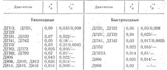
Parallel excitation generator circuit. The diagram is shown in Fig. 1.20. The armature current I I = I + I V at the brushes branches into the load current I and the excitation current I V. Usually the excitation current is small and amounts to (0.01-0.05) I R NOM . A rheostat RP is connected in series with the excitation winding to regulate the excitation. The rheostat allows you to change the excitation current and, therefore, the generator voltage.
The no-load characteristic of a self-excited generator is always removed with independent excitation (the field winding is disconnected from the armature and powered from an external source) and is therefore similar to the no-load characteristic of a generator with independent excitation.
Self-excitation of the generator. Since the field winding is connected to the armature terminals, the process of the initial occurrence of EMF, called the self-excitation process, is important.
Let us consider the process of self-excitation when the generator load is turned off, i.e. at idle.
The magnetic circuit of the machine has a small residual magnetic flux (approximately 2-3% of the nominal one). When the armature rotates in the residual flux field, a small emf is induced in it, causing some current in the field winding. With the appropriate direction, it increases the residual magnetic flux, the EMF in the armature increases and the process develops like an avalanche until it is limited by saturation of the magnetic circuit.
However, the process of self-excitation can develop only under certain conditions, called self-excitation conditions. Let's find out these conditions. The equation of Kirchhoff's second law for the excitation circuit has the form: E + еL= (Rв + Rя)iв, where еL= – d (Liв) /dt is the self-induction emf of the excitation circuit, which occurs when the excitation current increases;
L – total inductance of the field and armature windings; Rв is the sum of the resistances of the excitation winding and the control rheostat.
Since Rа « Rв, the equation takes the form:
Eя=Rв iв +
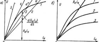
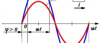
Let us show on the graph the idle speed characteristic E = f (Iв) and the excitation circuit characteristic – straight line Uв = Rв Iв
(Fig. 1.21). The segment ab, equal to E – Rв Iв = d (Liв) / dt, is proportional to the self-induction emf of the excitation circuit. It follows from the graph that at the point at the intersection of the characteristics d (Liв) /dt = 0, the growth of the excitation current stops Uв = E and the self-excitation process ends. The position of point B, called the operating point, depends on the resistance of the excitation circuit Rв » tgα. The larger it is, the steeper the straight line Uв = f (Iв) is and the operating point moves to the left. At a certain excitation circuit resistance Rв, кр = tan αкр, called critical, the voltage at the generator terminals is close to the residual EMF Eo and the generator is not excited.
From the above, the conditions under which the generator must be excited follow:
Ø presence of residual magnetization;
Ø coincidence in direction of the residual magnetic field and the field created by the excitation winding (field mismatch can occur if the excitation winding leads are connected incorrectly or if the armature rotation direction is inappropriate);
Ø the resistance of the excitation circuit must be less than critical;
Ø The speed of rotation of the armature must be higher than the critical speed.
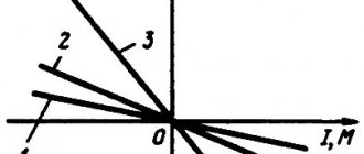
External characteristics. The external characteristic of the parallel excitation generator U= f (I) with Rв = const and n = nnom = const (Fig. 1.18, curves 2 and 2a) differs from the external characteristic of the independent excitation generator by a sharper decrease in voltage with increasing load. This is explained as follows: a decrease in voltage for the same reasons as that of an independent excitation generator leads to a decrease in the excitation current, an additional decrease in the emf of the generator. At rated load, the voltage reduction relative to the no-load voltage is 10-18%.
Regulating characteristic. The regulating characteristic of the generator Iв = f (I) with U= Unom = const and n = nnom = const is similar to the regulating characteristic of the independent excitation generator (Fig. 1.19, curve 2), but is somewhat steeper, which is explained by a more significant decrease in the generator voltage.
World of Science
Self-excitation of a generator with parallel excitation occurs when the following conditions are met:
1) the presence of residual magnetic flux of the poles;
2) correct connection of the ends of the field winding or the correct direction of rotation.
In addition, the resistance of the excitation circuit Rz at a given rotation speed n must be less than a certain critical value or the rotation speed at a given Rz must be higher than a certain critical value [2].
For self-excitation, it is enough that the residual flow is 2-3% of the nominal one. A residual flow of this magnitude is almost always found in a machine that has been running. A machine that has just been manufactured, or a machine that has been demagnetized for some reason, must be magnetized by passing current from an external power source through the field winding.
If the necessary conditions are met, the self-excitation process proceeds as follows. A small EMF, induced in the armature by the residual magnetic flux, causes a small current C in the excitation winding. This current causes an increase in the flux of poles, as a consequence, an increase in EMF, causing a further increase in the excitation current C, etc. This avalanche-like self-excitation process continues until the generator voltage reaches a steady value.
If the connection of the ends of the field winding or the direction of rotation is incorrect, then a current C appears in the opposite direction, causing a weakening of the residual flux and a decrease in the EMF, as a result of which self-excitation is impossible. In this case, it is necessary to switch the ends of the field winding or change the direction of rotation. You can verify that these conditions are met by monitoring using a voltmeter with small measurement limits for the armature voltage when closing and opening the excitation circuit.
The polarity of the generator terminals during self-excitation is determined by the polarity of the residual flow. If, for a given direction of rotation, the polarity of the generator needs to be changed, then the machine must be remagnetized by supplying current to the field winding from an external source.
Let's take a closer look at the process of self-excitation at idle.
In Fig. 2.14, and curve 1 is the idle speed (idle) characteristic, and straight line 2 is the so-called characteristic of the excitation circuit or the dependence Uз = RзИз, where Rз = const is the resistance of the excitation circuit, including the resistance of the adjusting rheostat.
§5.3. DC generators. Main characteristics
DC generators of various excitation systems can be combined into two main groups: generators with independent excitation and generators with self-excitation, which include generators of parallel, series and mixed excitation.Independent excitation generator.
The main statistical characteristics of the generators are analyzed at a constant angular velocity of the drive motor. Characteristics x.x. Eя= f(Iв) at Iа= 0 of the independent excitation generator () is shown in .
The type of such a characteristic can be most simply explained on the basis of formula (5.6), in which the dependence of the flux Fvot of the excitation current Iв is determined by the magnetization loop of the machine’s magnetic circuit. Characteristics x.x. is removed by decreasing from a value of approximately 1.25 Iv.nom to (-1.25 Iv.nom) (descending branch) and then increasing to the previous value (ascending branch). When Iв=0, the residual magnetization flux is maintained in the magnetic circuit and a residual EMF is induced in the armature, amounting to 1–4% of the nominal value. For the calculated characteristic x.x. the middle line is accepted. The external characteristic is constructed based on the equilibrium equation of the emf and voltages in the armature circuit, compiled according to Kirchhoff’s second law in steady state:
Uя= Eя- IяRя, (5.11) where Rя is the resistance of the armature winding.
This characteristic, constructed without taking into account the armature reaction, is depicted with a solid line. The characteristic is rigid, since the current and excitation flux do not depend on the armature current, and the voltage drop IаRя on the armature winding in the nominal mode is 5–15% of the EMF. Deviation of the external characteristic from the linear law (dash-dotted line) can be caused by the armature reaction. When changing from Rн to 0, the armature current continuously increases. The control characteristic Iв= f(Iя) at Uя =const determines the law according to which it is necessary to change the excitation current and, accordingly, the armature emf so that the output voltage remains constant at any armature current. As follows from (5.11) and (5.6), for this, with an increase in current Iа, it is necessary to increase the current Iв ().
Parallel excitation generator. A distinctive feature of self-excited generators is that an external source is not required to excite the machine. Let us consider the principle of self-excitation using the example of a parallel excitation generator () in x.x mode.
Self-excitation of the generator begins when two conditions are met: a) there is a residual magnetization flux Fost in the machine; b) the polarity of the excitation winding and the direction of rotation of the armature are such that the resulting excitation current creates a magnetic flux directed in accordance with Fost. In real DC machines, once magnetized at least once, a residual flux persists for a long time. When the armature rotates, the Fost flow induces an emf Eya ot in the armature winding, and a voltage x.x appears on the excitation winding. Ui ost, and a small current begins to flow through the excitation winding. This current creates a magnetic flux directed in accordance with Fost and reinforcing Eya. The excitation current increases, and the excitation process continues according to the cycle described above. The external characteristic of the parallel excitation generator (), where the load current Iн = Iя-Iв, differs from the characteristic of the independent excitation generator, since a decrease in Uя with an increase in Iн leads simultaneously to a decrease in Iв and, accordingly, Ея. The characteristic becomes less rigid. In addition, in short-circuit mode voltage Uв=Uя =0 and EMF and armature current must be equal to zero. However, in a real generator at Uв = 0, the flow Ф ≠ 0 and is equal to the flow Fost. This flow induces an emf in the armature, and short-circuit current flows through it. Is.c., but the value of this short-circuit current not much. Thus, when Rн changes from ∞ to 0, the currents Iн and Iz respectively increase only up to a certain value, called critical Icr, and then decrease. Regulating characteristic and i.e. characteristics. The parallel excitation generator has the same appearance as that of the independent excitation generator.
Dynamic characteristics. Let's consider the dynamic characteristics using the example of analyzing transient processes in an independent excitation generator when DC voltage Uv is applied to the excitation winding. In the analysis, we will accept the assumptions about the linearity of the magnetization curve of the machine and the absence of armature reaction. The transient process in the excitation circuit is described by a differential equation compiled according to Kirchhoff’s second law:
Uв= iвRв + Lв· diв/dt, (5.12) where Rв and Lв are the active resistance and inductance of the excitation winding.
The armature emf is determined in accordance with (5.6)
ея=kkфωiв , (5.13) where kф is the proportionality coefficient between the flux and the excitation current: Ф= kфiв.
We determine the current from (5.13) and substitute the resulting expression into (5.12). As a result, we obtain a differential equation that determines the transient process in the generator in the idle mode:
deя/dt ·(Lв/Rв) + ея= kkфωUв/Rв. (5.14)
The transition function, which determines the law of change in time of the output quantity with a stepwise change in the input quantity, is found as a solution to the differential equation (5.14) with zero initial conditions (t = 0, eя = 0). This is an exponential
ey = Eя (1-e[t/τв]), (5.15) where τв – electromagnetic time constant of the excitation winding; Eя = ku0 Uв is the steady-state value of the armature emf.
Generator voltage transfer (gain) coefficient in idle mode. ku0 is the ratio of the increments of the armature emf and the excitation voltage in steady state:
ku0 = kkфω /Rв. (5.16)
Equation (5.14) in operator form taking into account (5.16) has the form
τвp ея(p)+ ея(p)= ku0Uв(p). (5.17)
Based on (5.17), we write the transfer function of the generator:
W(p) = eя(p) /uв(p) = ku0 /(τвp+1). (5.18)
From expression (5.18) it is clear that the independent excitation generator in the x.x mode. is an aperiodic link. Transient processes in load mode naturally differ from processes at idle. In this case, the nature of the differences significantly depends on the nature of the load. As an example, let's consider the simplest case: the generator operates on an active load Rн. Equations compiled according to Kirchhoff’s second law for the armature circuit and load, when written in operator form, have the form
eя(p)= (Rя +Lяp)iя(p)+un(p), (5.19)
un(p) = Rнiя(p), (5.20)
where iа(p) and un(p) are operator images of the armature current and load voltage; Rya and Lya are the inductance and active resistance of the armature winding. Substituting iа(p) from (5.20) into (5.19) and then from (5.19) into (5.17), we obtain the operator equation
(τвp+1)(τнp+1)un(p) = kuuв(p), (5.21)
where τtan = Lя /(Rя+Rн) – time constant of the armature-load circuit; ku= ku0Rн /(Rя+Rн) – voltage transfer coefficient at load. Based on (5.21), we obtain the transfer function
W(p) = un(p) /uв(p) = ku /(τвp+1)(τнp+1), (5.22)
those. with an active load, the generator can be represented by two aperiodic links connected in series.
Back | Contents | Forward
To main§ 111. Methods of exciting DC generators
Depending on the method of powering the excitation winding, modern DC generators use independent magnetic flux excitation and self-excitation. With independent excitation (Fig. 154, a), the excitation winding is connected to an auxiliary source of direct current energy. To regulate the excitation current I
in the winding circuit resistance
r
p is switched on.
With such excitation, the current Iv
does not depend on the current in the armature
Ii
.
The disadvantage of independent excitation generators is the need for an additional energy source. Despite the fact that this source usually has low power (several percent of the power of generators), the need for it is a great inconvenience and therefore independent excitation generators find limited use in special installations (HD) and in high-voltage machines in which the excitation winding is powered from armature chains are unacceptable for design reasons. Self-excited generators have wider applications. Depending on the connection of the excitation winding, they can be parallel (Fig. 154, b), sequential (Fig. 154, c) and mixed (Fig. 154, d) excitation. For parallel excitation generators, the current I
is small (several percent of the rated armature current), and the field winding has a large number of turns.
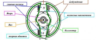
With series excitation, the excitation current is the armature current and the excitation winding has a small number of turns. With mixed excitation, two excitation windings are placed at the poles of the generator - parallel and serial. The process of self-excitation of DC generators proceeds the same way for any excitation scheme. Let us consider the process of self-excitation of a parallel excitation generator, which has received the most widespread use. Some prime mover rotates the armature of the generator, in the magnetic circuit (yoke and pole cores) of which a small residual magnetic flux Φrest is preserved. This magnetic flux is induced in the winding of the rotating armature. d.s. E
rest, which is a few percent of the rated voltage of the machine.
Under the influence of e. d.s. E
ost in a closed circuit consisting of an armature and an excitation winding, a current
I
century flows.
The magnetizing force of the field winding I
вωв (ωв is the number of turns) is directed in accordance with the flow of residual magnetism, increasing the magnetic flux of the machine Φ
m
, which causes an increase in both e.
d.s. in the armature winding E
, and the current in the field winding
I
.
An increase in the latter causes a further increase in Φ m
, which in turn increases
E
and
I
in.
Due to the saturation of the steel of the magnetic circuit of the machine, self-excitation does not occur indefinitely, but up to a certain voltage, depending on the speed of rotation of the machine’s armature and the resistance of the field winding circuit. When the steel of the magnetic circuit is saturated, the increase in magnetic flux slows down and the self-excitation process ends. An increase in resistance in the field winding circuit reduces both the current in it and the magnetic flux excited by this current. Therefore, e decreases. d.s. and the voltage to which the generator is excited. A change in the rotation speed of the generator armature causes a change in e. d.s., which is proportional to the speed, as a result of which the voltage to which the generator is excited also changes. Self-excitation of the generator occurs only under certain conditions, which boil down to the following. 1. The presence of a flow of residual magnetism. In the absence of this flow, no e is created. d.s. E
ost, under the influence of which current begins to flow in the excitation winding, so that excitation of the generator will be impossible.
If the machine is demagnetized and has no residual magnetization, then a direct current from some foreign source of electrical energy must be passed through the excitation winding. After disconnecting the field winding, a residual magnetic flux will remain in the machine. 2. The field winding must be connected so that the magnetizing force of this winding increases the flux of residual magnetism. When the field winding is switched on oppositely, its magnetizing force will reduce the residual magnetic flux and, during prolonged operation, can completely demagnetize the machine. In this case, it is necessary to change the direction of the current in the excitation winding, i.e., swap the wires suitable for its terminals. 3. The resistance of the field winding circuit should not be excessively large; with a very high resistance of the excitation circuit, self-excitation of the generator is impossible. 4. The resistance of the external load should be relatively high, since with low resistance the excitation current will also be small and self-excitation will not occur. Previous page
| table of contents | Next page |
Generator idle characteristics
We bring a direct current generator with independent excitation into rotation at a speed ω in the absence of voltage on the excitation winding, and a voltage will appear at the armature terminals, which is called the residual magnetism voltage.
Circuit of a direct current generator with independent excitation.
We apply voltage to the excitation winding and increase the current in the excitation winding using Rv. Current in the field winding is needed until the generator reaches the saturation region. Now we smoothly reduce the current in the excitation winding to zero. When the excitation current is equal to zero, we change the polarity at the generator terminals and begin to increase the current in the excitation winding to the saturation region, then we reduce this current to zero, change the polarity on the excitation winding and increase the current in the excitation winding until saturation. We get a complete idle speed characteristic.
Characteristics of idle running of a direct current generator with independent excitation.
The complete idle speed characteristic of the generator is a hysteresis loop and is related to the type of steel from which the generator is made. The area of the hysteresis loop is equal to the losses due to the magnetization reversal of steel.
The idle speed characteristic consists of 2 branches: the upper one is called descending, the lower one is called ascending.
The narrower the hysteresis loop, the smaller the losses; in addition, with a narrow loop, there will be less voltage discrepancies on the ascending and descending branches of the no-load characteristics.
For calculations and research, the average idle speed characteristic is used, which passes through zero in the middle of the hysteresis loop.