Author: zaCCCPanec
05 May 2022 13:01
Tags: interesting power transmission supports technology energy
22222
16
What could be more ordinary than power lines? Power line supports are one of the most common engineering structures, and they are always in front of our eyes. However, this area also has its own technological subtleties and even scope for technical progress. Overhead power lines that are not very noticeable to us are acquiring a new look and a new design.
0
See all photos in the gallery
Most often we imagine a power line support in the form of a lattice structure. About 30 years ago this was the only option, and even today they continue to be built.
0
A set of metal corners is brought to the construction site and, step by step, a support is screwed together from these standard elements.
×
0
Then a crane arrives and places the structure vertically. This process takes quite a lot of time, which affects the timing of laying lines, and these supports themselves with dull lattice silhouettes are very short-lived.
0
The reason is poor corrosion protection. The technological imperfection of such a support is complemented by a simple concrete foundation. If it is done in bad faith, for example using a solution of inadequate quality, then after some time the concrete will crack and water will get into the cracks. Several freeze-thaw cycles, and the foundation needs to be redone or seriously repaired.
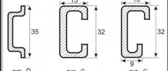
Types and types
Power lines can be divided into two large groups - overhead and underground. They are classified according to many criteria, ranging from purpose to current parameters. Different types of devices are used for different purposes. They conduct electricity to homes, businesses, streetlights, stores, billboards and other structures.
What types of power lines are there?
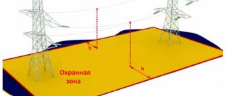
It is useful to know what voltage is transmitted along power lines, since each voltage has its own safe zone from wires. Let me give an example of the relationship between voltage and safe distance to it:
- For power lines 0.4 kV – 2 meters
- Power lines 1 - 20 kV - 10 meters
- Power line 35 kV – 15 meters
- Power line 110 kV – 20 meters
- Power lines 150 - 220 kV - 25 meters
- Power lines 220 - 500 kV - 30 meters
- Power line 750 kV – 40 meters
- Power line 1150 kV – 55 meters
Knowing the safe distance to power lines, you need to learn how to visually determine the voltage.
Methods of protection against electromagnetic radiation
As you gradually move away from the power line, magnetic radiation decreases. SanPiN indicates the distance when it reaches an acceptable value, but does not disappear completely. Professionals say that a completely safe distance is 10 times the permissible distance.
Layout of poles next to a residential building
Additionally, the house has wires and electrical appliances. During operation, they also emit electromagnetic waves at a distance of up to 2 meters from the compressor and heating elements.
The most dangerous are irons and refrigerators. People receive a large share of radiation from televisions, since they spend a long time in front of them. As a result, all radiation is summed up, and the result is a value that exceeds what is safe for humans.
Residential buildings located closer than 100 meters from household voltage lines and 200 meters from high-voltage lines must be protected from electromagnetic radiation.
Power line supports and other visible elements
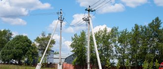
To ensure that the wire is securely held, supports are used. In the simplest case, these are wooden poles. But this design is applicable only to lines up to 35 kV. And with the increase in the value of wood, reinforced concrete supports are increasingly used in this stress class. As the voltage increases, the wires must be raised higher and the distance between phases greater. In comparison, the supports look like this:
Power line supports
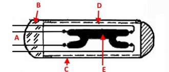
In general, supports are a separate topic, which is quite extensive. For this reason, we will not delve into the details of the topic of power transmission line supports here. But in order to briefly and succinctly show the reader its basis, we will show the image:
Support Attributes
To conclude the information about overhead power lines, we will mention those additional elements that are found on the supports and are clearly visible. This
- lightning protection systems,
- as well as reactors.
The first ones contain a special cable, which is located above the wires, and pin lightning rods. The latter are designed to limit the rate of current rise during a short circuit. The reactor is essentially a choke.
Reactors on power transmission towers
In addition to the listed elements, several more are used in power transmission lines. But let’s leave them outside the scope of the article and move on to cables.
Cable power transmission systems
Power lines are not only overhead, but also cable. They are power wires laid in or under the ground. Elements of such networks can also be located under water or in parts of buildings and other structures. Compared to overhead power lines, ground cable lines (this abbreviation means cable lines) have the following advantages:
- protection from weather, lightning strikes, falling branches and trees, as well as other negative external influences;
- smaller area, as well as the ability to more freely combine the line with other structures;
- safety for people and animals.
According to the conditions of passage, cable lines are divided into underground, underwater and located in buildings. Their classification by purpose, voltage and current nature is identical to that of overhead lines. There are also several types of CLs with different types of insulation. Among them are:
- Rubber. It is flexible and elastic. Quite reliable, but has a low service life and requires constant replacement.
- Made from PVC. An option with a low price, high elasticity and good reliability. Most often used.
- Polyethylene. It is used for lines laid in aggressive conditions and in contact with acids and alkalis. Unvulcanized polyethylene insulation deteriorates when exposed to high temperatures.
- Paper. Rarely used. The paper is impregnated with a special chemical composition, which gives it insulating properties.
- Fluoroplastic. Reliable and resistant to mechanical, temperature and other damage type of insulation.
- Butter. Requires special equipment that will maintain the required oil pressure. It is not currently produced and is gradually being dismantled, being replaced by other types. The reason for refusing such insulation is low reliability and fire hazard.
In order to lay underground power lines, various types of structures are used. They are necessary so that the wires can be maintained and repaired if necessary. The most common types of structures are:
- Tunnels. Enclosed corridors containing pre-installed structures for securing cables. These tunnels are quite spacious - an adult can walk freely through them. This is necessary to provide comfortable conditions for repair, installation and maintenance of cables.
- Channels. Constructions carried out at shallow depths underground. They can be laid both in the soil and under the floor covering. It is impossible to walk and move through these channels, unlike tunnels. If for some reason you need access to them, the covering will have to be removed.
- Mines. Vertical corridors with a rectangular cross-section. They come in different sizes - the largest ones are equipped with a ladder, with the help of which a person can get to the wires. Small impenetrable mines also exist - in order to carry out repair work in them, it is necessary to remove one of the walls.
- Cable floors. These are small technical rooms with a standard height of 1.8 m. Their upper and lower surfaces are floor slabs.
- Cable blocks. A complex structure consisting of several wells and laying pipes.
- Cameras. Structures located underground, covered with a reinforced concrete slab. Usually used to connect several sections of cable lines to each other.
- Overpasses and galleries. Horizontal inclined structures. There are both walk-through and non-pass-through, as well as above-ground or underground. The difference between them is that the overpass is an open structure, and the gallery is a closed one.
No tags for this post.
Kinds
Power lines are used to move and distribute electricity. Types of lines can be divided:
- by type of cable arrangement - aerial (located in the open air) and closed (in cable ducts);
- by function - ultra-long-distance, for highways, distribution.
Overhead power lines can also be divided into subtypes, which depend on the conductors, type of current, power, and raw materials used. These classifications are described in detail below.
Alternating current
Based on the type of current, power lines can be divided into two groups. The first of them is DC power lines. Such installations help to minimize losses when moving energy, and therefore are used to transmit current over long distances. This type of power line is quite popular in European countries, but in Russia such power lines can be counted on one hand. Many railroads operate on alternating current.
Power transfer circuit
Direct current
The second group is DC power lines, in which the energy is always the same regardless of direction and resistance. Almost all installations in Russia are powered by direct current. They are easier to produce and operate, but losses when moving current very often reach 10 kW/km in six months on a power line with a voltage of 450 kV.
Railway networks
About 7% of the electricity generated at Russian power plants is transmitted along overhead lines to railway facilities. In general, the length of the railway track is 43 thousand kilometers. Of these, 18 thousand km are powered by direct current of 3,000 Volts, and the remaining 25 thousand km are powered by alternating current of 25,000 Volts.
The energy from electrified roads is used for more than just running trains. It supplies industrial enterprises, settlements, and other real estate located along railways or in close proximity to highways. According to statistics, more than half of the electricity of the railway contact network is spent on power supply to facilities not included in the transport infrastructure.
Classification
Electrical energy is transmitted through metal wires, where the conductor is copper or aluminum. The method of laying wires differs:
- By air - by air lines;
- In soil (water) - cable lines;
- Gas-insulated lines.
The listed types of power lines are the main ones. Experiments are being conducted on wireless energy transfer, but at present this method is not widespread in practice, with the exception of low-power devices.
Wireless charger
By type of current
Most existing power lines are designed to operate with alternating current, which is due to the ease of voltage conversion.
Certain types of lines operate with direct current. They are intended for some applications (power supply of contact networks, powerful DC consumers), but the overall length is small, despite lower losses on the capacitive and inductive components.
According to the operating mode of neutrals in electrical installations
- Networks with solidly grounded neutral;
- Networks with isolated neutral;
- With resonant grounded neutral;
- With effectively grounded neutral.
According to the operating mode depending on the mechanical condition
The main operating mode of the overhead line is normal, when all wires and cables are in good condition. There may be cases when some of the wires are missing, but the power line is in operation:
- In case of a complete or partial break - emergency mode;
- During installation of wires and supports, use installation mode.
By purpose
- Intersystem (long-distance) – for combining several energy systems. This includes overhead lines 500 kV and above;
- Trunk – for connecting power plants into a network within one power system and supplying electricity to central substations;
- Distribution - for connecting large enterprises and settlements with central substations;
- overhead lines of agricultural consumers;
- Urban and rural distribution network.
Installation method
The main criterion by which power lines are classified is the constructive method of transmitting energy. Lines are divided into the following types:
- aerial - electric current is transmitted through wires suspended on special supports;
- cable - transmission of electric current is carried out through power cables laid in the ground, cable ducts or other types of engineering structures.
What do the inscriptions on overhead line supports mean?
Surely many have seen the inscriptions on power transmission poles in the form of letters and numbers, but not everyone knows what they mean.
Photo 10. Designations on power line supports.
They mean the following: a capital letter indicates the voltage class, for example T-35 kV, S-110 kV, D-220 kV. The number after the letter indicates the line number, the second number indicates the serial number of the support.
- T means 35 kV.
- 45 is the line number.
- 105 is the serial number of the support.
This method of determining power line voltage by the number of insulators in a garland is not accurate and does not provide a 100% guarantee. Russia is a huge country, therefore, for different operating conditions of power lines (cleanliness of the surrounding air, humidity, etc.), designers calculated different numbers of insulators and used different types of supports. But if you approach the issue comprehensively and determine the voltage according to all the criteria described in the article, then you can quite accurately determine the voltage class. If you are far from the electric power industry, then for a 100% determination of the power line voltage, it is still better for you to contact your local energy company.
Anyone who regularly deals with overhead power lines knows that different voltages on the lines are characterized by individual design features of the supports. Therefore, for an experienced electrician, nothing is easier than to determine the voltage on it by the appearance of a power line support.
The design of the support itself, what insulators are installed on it, how many wires, how they are placed - all this, upon visual inspection, will allow a specialist to draw a conclusion about the voltage of a particular high-voltage line. Although often, in order to understand what voltage is on the line, you just need to look at the insulators, because their length is strictly regulated by the PUE (the first chapter of the “Rules for Electrical Installations”).
The average person may have a question: why does a non-specialist need this knowledge? Why does an ordinary person who has nothing to do with the operation of power lines need to know about the design of insulators and the construction of supports? Why extra knowledge? The point is that this knowledge may not only be useful, but even help save someone’s life.
There are many examples where lack of knowledge about electrical safety led to deaths, in particular, some power line supports should not be approached closer than a certain distance at all, this can be deadly. Moreover, it is unacceptable to locate any mechanisms near some power lines. The table above from Chapter 4 of the PUE reflects this situation.
Industrial accidents caused by people's ignorance of electrical safety techniques and simply lack of awareness are by no means uncommon.
The builders needed to turn on the hammer drill, but electricity had not yet been supplied to the site. Nearby, they saw low power transmission poles and decided to connect the tool directly to the wires. Without thinking twice, the workers took a long wire as an extension cord, stripped its ends, rolled them into improvised hooks, and began hooking them to the wires using a wooden pole. The power line turned out to be not 380 volts, as they thought, but 10,000 volts. One of the builders miraculously survived, but was seriously injured.
One more example. Long metal pipes were brought to the site, the slinger began unloading the truck, completely underestimating the fact that there was a 110 kV high-voltage power line running nearby. During the unloading work, one of the pipes ended up a few centimeters from the wire.
As soon as the slinger touched the pipe while standing on the ground, an electrical breakdown occurred through the air, and the person died. And all he needed was to look at the insulators of the ill-fated power line, and see that there were as many as 6 of them in each garland... After all, the higher the voltage of the power line, the longer the garlands of insulators on it would be.
High-voltage lines in the 0.4 kV class are characterized by small glass or porcelain pin insulators mounted on steel hooks or pins. The supports are often reinforced concrete, but you can still find wooden ones in some places. There are two wires here if the line is single-phase, or four or more if it is a three-phase line. The voltage between conductors is 220 or 380 volts. Such lines can be found in collective gardens and in small villages, where they stand along the roads.
High-voltage 10 kV power lines have larger insulators than 0.4 kV class lines. Wide glass or porcelain insulators of brown color, they are located vertically on pins or in the form of hangers on the corners, one or two per wire, sometimes in the form of a garland of two insulators, and sometimes just three separate large insulators on hooks and on a pin. There are three wires in the line.
Through such lines, laid along roads, electricity is supplied, for example, from a city substation to a village. So, the main distinguishing feature of a 10 kV line is large or double wide insulators on three wires. Previously, when 6 kV lines were widely used, they looked exactly the same.
35 kV lines have much larger insulators. Also pin or pendant, but the number of insulators in the garland is from three to five. Here they are also porcelain or glass. The quantity depends on the type of insulators and the design of the support.
Reinforced concrete supports, or completely metal supports, have current-carrying conductors widely spaced from each other. These are not ordinary poles; transverse holders are necessarily used here, even if they are wooden (you can still find them here and there).
In high-voltage lines of 110 kV, exclusively suspended garlands of insulators are used. Glass or ceramic garlands are composed of at least six elements, the number of which most often varies from six to nine depending on the design of the support, but in some cases there may be more than nine insulators.
The support itself can be reinforced concrete with metal cross members or completely metal, assembled like a truss. Each wire on a separate insulator is a single wire. Thus, if the wires are single, and the insulators are made up of 6-8 elements, then you most likely have a power line with a voltage of 110 kV.
The device is similar to a 110 kV power line, but there are ten insulators per garland, often double-sided insulators. There can be from ten to fourteen insulators. So, if in front of you is a reinforced concrete or metal support with 10-14 insulators, then most likely this is a 220 kV power line. All power lines with voltages of 110 kV and more have suspended insulators. You cannot approach the conductors closer than 2 meters - it is dangerous for life, as in the case of a slinger.
There are 14 hanging insulators per garland, but there are two wires for each phase. The support is reinforced concrete or metal. Overhead power lines at 330 kV are characterized by a danger zone of 2.5 meters in each direction from the side wires; a person cannot be closer - it is life-threatening. If there are from 14 to 20 insulators, if there are two wires, this is a 330 kV power line. The supports can be either metal or reinforced concrete.
There are 20 or more insulators per garland, but there are already three wires per phase. The typical danger zone for humans is closer than 3.5 meters from the side conductors. If there are three conductors and 20 insulators per phase, this is a 500 kV power line.
There are 20 or more insulators per garland, just like 500 kV power lines, but there are already 4-5 wires per phase. The typical danger zone is 5 meters from the side conductors. If the conductors are arranged 4 pieces in the shape of a square or 5 pieces in the shape of a ring, then you have a 750 kV power line.
Finally, the 1150 kV overhead line has eight wires at the corners of the octagon for each phase. Insulators from 50 pieces per garland. If there is such a line in front of you, then it may be a section of the Siberia-Center high-voltage power transmission line. You should not approach the wires closer than 8 meters.
A high-voltage power pole or transmission tower is a tall, usually lattice frame structure designed to connect overhead conductors to transmit electrical power. Overhead line supports support wires at the required distance from the surface of the earth, wires of other lines, roofs of buildings, etc.
All high-voltage power lines require the installation of special elements to ensure the stability of their operation. One of the most frequently used elements is the high-voltage intermediate support. This type of engineering structures is installed on straight sections through which overhead power lines pass. The main function performed by the intermediate support of an overhead line is to support wires and cables. It is not designed to withstand long-term stress caused by wire tension. However, in emergency situations (for example, in the event of a wire break), the structure perceives this type of load, which is transmitted by the remaining intact wires.
The supports of overhead power lines of 35-500 kV are made of rolled steel, parts of which are welded. To protect against corrosion, the surface of metal supports is galvanized or periodically painted with special paints. However, they have high mechanical strength and a long service life. Install metal supports on reinforced concrete foundations. With another assembly technology, hot-dip galvanized frame parts can be bolted together. This is more reliable and also very convenient, since the resulting parts are very compact and can be easily transported.
220 kV high voltage towers support wires and cables at a certain height above ground level. The wires from the overhead power line supports are insulated with special insulators. With the help of linear fittings for power transmission lines, the wires are fixed to insulators, and the insulators are fixed to traverses.
Electrical overhead lines (OHL) are designed for the transmission and distribution of electrical energy through wires located in the open air and attached to various supporting structures (OHL supports). Overhead power lines can have voltages up to and including 1 kV and higher than 1 kV (3, 6, 10, 35, 110, 220, 330 kV and higher on the standard voltage scale).
Overhead lines consist of the following main structural elements: overhead lines of various types of supports (intermediate, corner, anchor) for hanging wires and lightning protection cables; high-voltage wires of various designs and cross-sections for transmitting electric current through them; lightning protection cables to protect lines from lightning discharges; high-voltage insulators assembled in garlands to isolate wires from grounded parts of the support; linear fittings for attaching wires and cables to insulators and supports, as well as for connecting wires and cables; grounding devices for draining lightning currents or short circuits into the ground.
The most important characteristics of overhead power lines
:
- l – line span length (distance between adjacent supports);
- f – the greatest sag of the wire in the span;
- h – the smallest (overall) permissible distance from the lowest point of the wire to the ground;
- l is the length of the insulator string;
- a is the distance between adjacent wires (phases) of the line;
- H – full height of the support.
The design parameters of an overhead power line depend on the rated voltage of the line, on the topography and climatic conditions of the area, as well as on technical and economic requirements.
The permissible distance from the lowest point of the wire to the ground is 5-7 m in an uninhabited area, and 6-8 m in a populated area.
The supports of overhead power lines are built in open areas and are therefore exposed to various atmospheric influences, which, depending on the geographical location, manifest themselves to varying degrees and have a major impact on the reliability of the line. Therefore, to ensure reliable operation of the overhead line, it is necessary to protect it with various devices depending on the type of climatic influences.
The operation of the lines is affected by combinations of low temperatures with the highest wind speeds, as well as the temperature accompanying the process of ice and frost formations. When calculating overhead line supports and their elements, climatic conditions must be taken into account - wind pressure, ice wall thickness, air temperature, degree of aggressive environmental influences, intensity of thunderstorm activity, dancing of wires and cables, vibration.
220 kV overhead power line is a device for transmitting electricity through wires located in the open air and attached with insulators and fittings to high-voltage supports or brackets and racks. 220 kV overhead power lines are mainly used for communication between power plants, large consumers and distribution zones. 330 kV overhead power lines are built over long distances, for example, for communication between powerful power plants and electrical substations. The voltage of an overhead power line can be determined visually: if high-voltage supports have insulators from 10 to 15, then this is a 220 kV power line. If the power line wires bifurcate then the power line is 330 kV. In the upper part of the high-voltage support above the wires, lightning protection cables are installed to protect overhead lines from lightning surges.
On overhead power lines with voltages above 1 kV, bare wires and cables are used. Being in the open air, they are exposed to the atmosphere (wind, ice, temperature changes) and harmful impurities of the surrounding air (sulfur dioxide from chemical plants, sea salt) and therefore must have sufficient mechanical strength and be resistant to corrosion (rusting).
Previously, copper wires were used on overhead lines, but now they use aluminum, steel-aluminum and steel, and in some cases, wires made of special aluminum alloys - Aldrey, etc. Lightning protection cables are usually made of steel.
Lightning protection cables are suspended above the wires to protect them from atmospheric surges. On lines with voltages below 220 kV, cables are suspended only at the approaches to substations. This reduces the likelihood of blocking line wires near the substation. On lines with a voltage of 220 kV and above, the cables are suspended along the entire line. Typically steel wire ropes are used.
Previously, cables on lines of all rated voltages were tightly grounded at each support. Operating experience has shown that currents have appeared in the closed circuits of the grounding system - cables - supports. They arose as a result of the action of EMF induced in the cables by electromagnetic induction. At the same time, in a number of cases, significant losses of electricity occurred in repeatedly grounded cables, especially in ultra-high voltage lines.
Research has shown that when high-conductivity (steel-aluminum) cables are suspended on insulators, the cables can be used as communication wires and as current-carrying wires for power supply to low-power consumers.
To ensure the appropriate level of lightning protection of the lines, the cables must be connected to grounded cables through spark gaps.
Power line crossbars serve to support wires above the ground - these are crossbars to which insulators are attached. The grid and diaphragm are components of the metal structure of high-voltage lines. Foundations are designed to reliably strengthen the trunk in the ground. The support cable is used to support the lightning protection cable. The cable rack is easy to recognize on most high-voltage power transmission towers - these are sharp trapezoidal “spiers” at the very top. There are two cable supports on the U-shaped metal supports. There are high-voltage power transmission line supports of 220 kV and without cable supports. Intermediate supports 220 kV (P220-2t, P220-3, P330-2T, P330-2T+5, P330-3T, P330-3T+5) are installed on straight sections of the line. On intermediate metal supports 220 kV with suspended insulators, the wires are fixed in supporting garlands hanging vertically; on traverses with pin insulators, the wires are secured by wire knitting. In both cases, the intermediate elements perceive horizontal loads from wind pressure on the wires, vertical forces from the weight of the wires, insulators and the actual weight of the power line support. With unbroken wires and cables, intermediate supports of 330 kV, as a rule, do not perceive the horizontal force from the tension of the wires and cables in the direction of the overhead power line and therefore can be made of a lighter design (the weight of the power line support is reduced by 2-3 times) than the designs of other types, for example, end ones, which absorb the tension of wires and cables. However, to ensure reliable operation of the 330 kV transmission line, the intermediate structures must withstand some loads in the direction of the line. At angles of rotation of the power line of more than 20°, the load on the 330 kV intermediate supports increases significantly, as a result of which the support structure has a more massive weight; at the same time, the supporting garlands, deflecting under the influence of gravity components, require an increase in dimensions.
Intermediate high-voltage supports with voltage 220 kV, type P220 and PS220
| Name and type of power line support | Height to the bottom of the traverse, m(H) | Weight of power line support coated with BT varnish, kg | Weight of power line support with zinc coating, kg |
| P220-2 | 22,5 | 6208 | 6450 |
| P220-2t | 22,5 | 6327 | 6573 |
| P220-2t+5 | 27,5 | 7764 | 8065 |
| P220-2+5 | 27,5 | 7645 | 7940 |
| PS220-2 | 17,5 | 5503 | 5717 |
| PS220-2t | 17,5 | 5624 | 5843 |
For an experienced electrician who has been working with overhead power lines for many years, it will not be difficult to visually determine the voltage of an overhead line by the type of insulators, supports, and the number of wires in the line without any instruments. Although in most cases, to determine the voltage on an overhead line, you just need to look at the insulators. After reading this article, you will also be able to easily determine the voltage of overhead lines using insulators.
Photo 1. Pin insulators for voltage 0.4, 6-10, 35 kV.
Every person should know this! But why, why does a person far from the electric power industry need to be able to determine the voltage of an overhead power line by the appearance of the insulators and the number of insulators in the overhead power line garland? The answer is obvious, it's all about electrical safety. After all, for each voltage class of overhead lines, there are minimum permissible distances, closer than which approaching the overhead line wires is deadly.
In my practice, there were several accidents associated with the inability to determine the voltage class of overhead lines. Therefore, below is a table from the safety rules, which indicates the minimum permissible distances, the closer of which it is deadly to approach live parts that are energized.
Table 1. Permissible distances to live parts that are energized.
*D.C.
The first incident occurred at the construction site of a country house. For some unknown reason, there was no electricity at the construction site; a 10 kV overhead line ran near the unfinished house. Two workers decided to power an extension cord from this overhead line to connect power tools. After stripping two wires on the extension cord and making hooks, they decided to use a stick to hook them to the wires. On a 0.4 kV overhead line, this scheme would work. But since the voltage of the overhead line was 10 kV, one worker received serious electrical injuries, and miraculously survived.
The second incident occurred on the territory of the production base while unloading pipes. A working slinger was unloading metal pipes from a truck using a truck crane in the coverage area of a 110 kV overhead line. During unloading, the pipes bent so that one end came dangerously close to the wires. And even despite the fact that there was no direct contact of the wires with the load, a breakdown occurred due to the high voltage and the worker died. After all, you can be killed by electric shock from a 110 kV overhead line even without touching the wires, you just need to get close to them. I think it’s now clear why it is so important to be able to determine the voltage of overhead lines by the type of insulators.
The main principle here is that the higher the power line voltage, the greater the number of insulators in the garland. By the way, the highest voltage power line in the world is located in Russia, its voltage is 1150 kV.
The first type of line whose voltage you need to know in person is a 0.4 kV overhead line. These overhead line insulators are the smallest, usually pin insulators made of porcelain or glass, mounted on steel hooks. The number of wires in such a line can be either two, if it is 220V, or 4 or more, if it is 380V.
Photo 2. wooden support of 0.4 kV overhead line.
The second type is VL-6 and 10 kV; outwardly they do not differ. 6 kV overhead lines are gradually becoming a thing of the past, giving way to 10 kV overhead lines. The insulators of these lines are usually pin-type, but are noticeably larger than 0.4 kV insulators. Suspension insulators, one or two in a garland, can be used on corner supports. They are also made of glass or porcelain, and are mounted on steel hooks. So: the main visual difference between the 0.4 kV overhead line and the 6, 10 kV overhead line is the larger insulators, as well as only three wires in the line.
Photo 3. Wooden support of 10 kV overhead line.
The third type is 35kV overhead line. Suspended insulators, or pin insulators, are already used here, but of a much larger size. The number of pendant insulators in a garland can be from three to five, depending on the support and type of insulators. The supports can be either concrete or made of metal structures, as well as wood, but then it will also be a structure, and not just a pole.
Photo 4. Wooden support of 35 kV overhead line.
110 kV overhead line from 6 insulators in a garland. Each phase, single wire. The supports can be reinforced concrete, wooden (almost never used) or assembled from metal structures.
220 kV overhead line from 10 insulators in a garland. Each phase is carried out with a thick single wire. With voltages above 220 kV, supports are assembled from metal structures or reinforced concrete.
Photo 5. Reinforced concrete support of 110 kV overhead line.
330 kV overhead line from 14 insulators in a garland. There are two wires in each phase. The security zone of these overhead power lines is 30 meters on both sides of the outermost wires.
Photo 7. 330 kV transmission line support.
500 kV overhead line from 20 insulators in a garland, each phase is carried out with a triple wire arranged in a triangle. Security zone 40 meters.
Photo 8. 500 kV transmission line support.
750 kV overhead line from 20 insulators in a garland. Each phase has 4 or 5 wires arranged in a square or ring. Security zone 55 meters.
Photo 9. 750 kV transmission line support.
Table 2. Number of insulators in an overhead line garland.
Composition of power lines
The composition of cable and overhead lines is different. For differentiation, we will consider each type of power line separately.
Components of an overhead power line
Overhead lines include many devices and structures. We list the main ones:
- supports;
- fittings and insulators;
- grounding devices;
- wires and cables;
- discharge devices;
- markers for identifying wires;
- substations.
In addition to their direct purpose, overhead lines are used as engineering structures for suspending fiber-optic communication cables. In this regard, on some lines the number of constituent elements is constantly growing.
Components of a cable power line
Cable lines are used to transmit electrical energy in places inaccessible for suspension along overhead line supports. The structure includes a power cable and input units at the substation and to end consumers.
Rationale for high voltage
It is customary to deliver electric current to consumers at 220 and 380 volts. However, in conditions of long lines this is not beneficial, since losses in sections longer than 2 km may not be comparable with the required power consumption.
In order to reduce losses over long distances, the power is increased and high voltage current is transmitted. To do this, step-up substations are used before transmission, and step-down transformers are placed in front of the consumer. So the transmission line looks like this:
Structural diagram of power lines
Purpose of overhead power lines
Such overhead lines are called installations that are used to move and distribute electrical energy along cables located in the open air and held using special racks. Overhead lines are installed and used in a wide variety of weather conditions and geographic areas, and are prone to atmospheric influences (precipitation, temperature changes, winds).
Therefore, overhead lines must be installed taking into account weather factors, air pollution, installation requirements (for a city, field, village), etc. The installation must comply with a number of rules and regulations:
- economical cost;
- high electrical conductivity, strength of the ropes and racks used;
- resistance to mechanical damage and corrosion;
- be safe for nature and people, do not occupy a lot of free territory.
What do insulators look like?
Protective devices
Lightning protection conductors, arresters and grounding devices are used as protection. Grounding of metal supports is carried out by mechanically attaching the supporting structure to the ground loop. Grounding of reinforced concrete supports is especially important, since when current leaks, it begins to flow through the concrete reinforcement, having a destructive effect. The damage caused to the support will not be visually visible.
Important! For best protection, the security wire is placed above all others.
1.9.13
On overhead lines with a voltage of 6-20 kV with metal and reinforced concrete supports, the number of suspended disc insulators in supporting and tension garlands must be determined according to 1.9.12 and, regardless of the material of the supports, must be at least two.
On overhead lines with a voltage of 35-110 kV with metal, reinforced concrete and wooden supports with grounded garland fastenings, the number of disc insulators in tension garlands of all types in areas with the 1st-2nd SZ should be increased by one insulator in each garland compared to the quantity obtained according to 1.9.12.
On overhead lines with a voltage of 150-750 kV on metal and reinforced concrete supports, the number of disc insulators in tension garlands should be determined according to 1.9.12.
Determination of power line voltage
Of course, cable power lines are mostly hidden, and those located in the open air cannot always be distinguished visually.
But air lines can be identified by:
- The type of supports used in power transmission lines;
- The appearance and number of insulators;
- Seeing off;
- The size of the security zone;
- Letter marking on the supports (T – 35 kV, S – 110 kV, D – 220 kV).
Letter marking on the support
Therefore, next we will consider a system for determining the voltage value of power lines using basic visual criteria.
Health hazards from power lines
However, a voltage of 10 kV is considered safe for humans. It creates a background density not exceeding 10 μT (measured in microtesla). For comparison, the Earth's magnetic field is 30–50 μT.
Prohibited in the security zone of power lines
It differs from the radiation generated by overhead lines in that it has a constant or smoothly varying value. A current with a frequency of 50 Hz passes through the power line - this means that per second the current changes its direction 50 times, a complete oscillation occurs - an alternating current wave. The magnitude of the emitted magnetic field also changes with this frequency.
Note that the highest value of natural vibrations reaches 40 Hz. When constantly in the zone of magnetic waves with high levels, malfunctions occur in the human body. This is possible not only when standing under power lines for a long time, but also next to household electrical appliances, especially thermal ones. The damage caused by the proximity of overhead lines can be compared with the health damage caused by a hairdryer, refrigerator, washing machine or laptop.
In the European Union countries, it is generally accepted that if the voltage in the power line wires is higher than 35 kV and the apartment is located closer than the standard size of the security zone plus 20 m, then, according to the health standards of the United Europe, such proximity can lead to a number of diseases of the nervous and cardiovascular systems .
Standard distances from supports
The distance from power lines and possible harm to health in such a case are absolutely dependent. Construction of housing in the European Union is permitted at a distance of 20 meters from the sanitary protection zone, if we take its value from Russian PUE standards.
All-Russian standards for the distance to residential buildings are stated above in this article.
Below is a table of European standards.
| Voltage, kV | Security zone according to PUE, m | EU norm for construction, m |
| 35 | 15 | 35 |
| 110 | 20 | 40 |
It is necessary to note that the site for individual housing construction or a dacha may partially be closer to the high-voltage line than the minimum distance to the residential building. In the technical passport this strip is indicated as an encumbrance zone. On this land you can plant a vegetable garden, a garden and put up a fence. You cannot build a house and construct outbuildings. A seating area in the yard should be located away from power lines.
Impact on human health
Thanks to research by scientists, it was found that exposure to electromagnetic fields has a negative impact on human health. Currents are formed in his body. This is explained by the conductivity of organs and tissues through which blood and lymph circulate.
An analysis of the studies showed that residents of houses located near power lines or substations developed cancer twice as often as residents of other areas. The field had an even stronger effect on the child’s health. Children fell ill with leukemia 4 times more often.
The negative impact of high-voltage lines on the following body systems has been recorded:
- cardiovascular,
- hematological,
- nervous,
- sexual,
- endocrine,
- immune.
It has been established that the health of people living near power lines gradually deteriorates over time. They are more likely to experience headaches, memory problems, muscle pain, and dizziness. The number of strokes and heart attacks is increasing. I am worried about insomnia and weakness. Women have problems bearing and giving birth to children. The health of newborns is weakened.
The harm a person receives when exposed to an electric field depends on the intensity and the duration of the effect on the body.
Valid values:
- in populated areas – 5 kV/m;
- when crossing roads – 10 kV/m;
- outside populated areas – 15 kV/m;
- in hard-to-reach places - 20 kV/m.
A person can be exposed to an electric field of 0.5 kV/m for a long time, without any negative impact on health.
If a person is required to stay in places of high tension, one must be guided by the following standards according to which the time of stay in the zone is:
- not limited at 5 kV/m;
- no more than 180 minutes at 10 kV/m;
- 90 minutes at 15 kV/m;
- 10 minutes at 20 kV/m;
- 5 minutes at 25 kV/m.
If these conditions are met, human health is restored within 24 hours.
If it is impossible to limit the time spent by working personnel at hazardous objects, workplaces are shielded with metal sheets, nets and other devices. Shrubs with a height of 3 meters and 6-meter trees planted under overhead lines give a good effect.
When exposed to electromagnetic fields in residential buildings, it is important to preserve the health of the people living there. For this purpose, sanitary standards have been developed (SanPiN 2971-84), regulating the minimum safe distance, the protective zone, from the power line to the nearest buildings.
Increased demands are placed on the location of ultra-high voltage routes. The distance from the overhead line to the populated area should be:
- at 750 kV not less than 250 m,
- at 1150 kV not less than 300 m.
Dimensions of the protected area
Let us immediately emphasize that the safe distance from power lines is measured perpendicular to the axis of the overhead line - the high-voltage line. The projection of the outermost wire onto the ground or the outer point of the support structure is taken as the reference point. The width of the sanitary zone directly depends on the voltage in the wires and is determined by SanPiN 2971-84. Electromagnetic radiation, its background, is measured at a height of 1 m above the soil.
Width of the security zone according to SanPiN standards in 2022
Please note that you cannot build, plant, or stay in the sanitary zone for a long time. Land for power transmission lines is prohibited from being sold and used for commercial purposes both in the city and in rural areas, on plots in SNT or individual housing construction.
Impact on the environment and ecology
Electromagnetic fields have a strong influence on all biological objects located near air routes: insects, plants, animals.
The proximity to high-voltage lines has a detrimental effect on bees. Insects become aggressive, restless, lose their working capacity and flight activity. There is a threat of death of queens and families.
Flying insects - beetles, mosquitoes, butterflies - tend to an area with a lower level of tension.
Plants change the shape of leaves, stems, flowers, extra petals and other developmental anomalies appear. According to some data, the electromagnetic field has a positive effect on the yield of agricultural crops, on the fruiting of berries and vegetables. Experiments have shown that after exposure to a high-intensity field, the seeds began to produce a higher percentage of germination and rapid germination.
The impact of overhead power lines on animals is just as negative as on people. Artiodactyls are the most sensitive. If the pasture is located in an area adjacent to an overhead line, a potential of 10 kV can be induced in the body of the animal, isolated from the ground by its hooves. When you touch grounded objects (grass, bush branches), a current pulse of 100 - 200 μA occurs. This value is not life-threatening. The health of the artiodactyl will not deteriorate, but it will experience unpleasant sensations. If wooden overhead line supports are treated with creosote, then contact with this substance can have adverse consequences for the animal.
Birds become victims of electrical discharges through direct contact with live parts and when touching the insulating parts of the wire suspension.
To minimize the harm caused to the environment by high-risk objects, it is necessary to use special protective devices.
High-voltage power lines are capable of locally affecting even the weather. It was recorded how power lines affect air flows. The cold air, having reached the high-voltage route (800 kV), began to flow around it.
In his work on the theory of atmospheric electricity, Russian scientist Lev Aleksandrovich Pokhmelnykh put forward the hypothesis that high-voltage power lines have an adverse effect on the environment. According to the scientist, global warming and the formation of an arid climate occur due to the ionization of the atmosphere by power lines, so the greenhouse effect has nothing to do with it.
Voltage in residential areas
Within cities, there are numerous power lines on the streets, the voltage of which usually does not exceed 10 kV. Such values do not pose a risk to human health. The wires provide electricity to homes; they pass over residential areas and fenced areas.
Mountain and power line supports Source neftegaz.ru
Standards for safe use are also taken into account here. Buildings and structures are located at a distance from power lines of at least 5 meters. This line is the front boundary along which all communications pass. All wires are within this zone, except for the cable connected to the house itself.
An insulator with a fixed wire is placed at a height of 275 cm on the wall of the building. It should not enter the building in the areas of bedrooms, children's rooms and living rooms. The use of storage rooms, utility rooms and corridors is allowed.
City and power line pylons Source fadedead.org
The wires can hang over the tracks no more than 350 cm. Moreover, this distance should be more than 6 meters above the tracks for cars.
In single-story residential areas, power lines are usually located on one side of the road. On the plan this place is marked with a red line. The distance from the power line support to residential buildings must fully comply with PUE standards. To connect the building from the opposite side to the wire, it is necessary to use additional poles. Insulators should be located at a height of 620 cm. The shortest distance from a 6 kV line to vegetation is 2 meters.
Harm to technology and means of communication
The increase in the length of electricity transmission routes across the country has led to the fact that the electromagnetic field of power lines began to affect the reception of television signals and radio communications.
What are the causes of radio interference from overhead lines, and why do they affect TV reception? As a result of a corona discharge in space, electromagnetic disturbances arise near the wires, which cause interference for radio receiving devices.
How does weather affect radio interference? Depending on meteorological conditions, interference may decrease, increase, or disappear temporarily. For example, when rain washes away contaminants from wires, the level of interference on radio channels and communication lines also decreases. They do not increase during fog or dew. But in rainy weather, the increase in interference on terrestrial television occurs in proportion to the intensity of the rain.
When using overhead line supports for the installation of fiber-optic communication lines, it is necessary to take into account that the fiber-optic line will be subject to an electromagnetic field. The potential induced in this case will cause its premature failure. To avoid this moment, you need to find the point of zero potential and attach the optical cable to it.
High-voltage power lines have an unsafe effect on steel main pipelines, including gas pipelines in the following cases:
- parallel running of the pipeline and power lines;
- at the places of their intersection;
- in places of approaching and moving away from each other.
The danger lies in the fact that the alternating electromagnetic field created by the overhead electric line affects the pipeline located in the ground. The induction that appears in this case leads to the formation of a longitudinal EMF in the pipeline. The health and life of service personnel is at risk.
How does this process affect the pipeline itself? Due to alternating current, electrolytic corrosion of the metal occurs. Electrical devices associated with the pipeline may fail. In addition, if a power line breaks, the pipeline may be under high voltage.
To ensure safety, pipeline protection devices (PPD) are used:
Does the magnetic field of overhead lines affect mobile communications and phones? Much depends on the operator, on the technical capabilities of the phone, on the distance to the power lines. At high humidity, when corona discharges are clearly audible, the connection at the support may be weak or even absent. But, in general, overhead lines do not have a significant impact on cellular communications.
The same can be said about the effect of overhead lines on drones and other radio-controlled models. Interference occurring on power lines can interfere with the control of these devices. But, basically, nothing interferes with the movement of quadcopters. They are even planned to be used for technological inspections of overhead electrical routes.
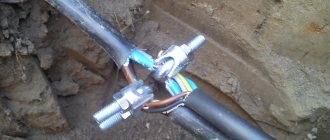
Why are the wires humming?
0
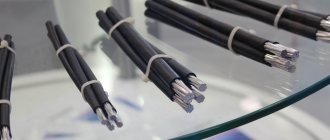
What about the wires? They hang high above the ground and from a distance look like thick monolithic cables. In fact, high-voltage wires are twisted from wire. A common and widely used wire has a steel core, which provides structural strength and is surrounded by aluminum wire, the so-called outer layers, through which the current load is transmitted. There is a lubricant between the steel and aluminum. It is needed in order to reduce friction between steel and aluminum - materials that have different coefficients of thermal expansion. But since aluminum wire has a round cross-section, the turns do not fit tightly against each other, and the surface of the wire has a pronounced relief. This deficiency has two consequences. Firstly, moisture penetrates into the cracks between the turns and washes away the lubricant. Friction increases and conditions for corrosion are created. As a result, the service life of such a wire is no more than 12 years. To extend the service life, repair cuffs are sometimes put on the wire, which can also cause problems (more on this below). In addition, this wire design helps create a clearly visible hum near the overhead line. It occurs due to the fact that an alternating voltage of 50 Hz creates an alternating magnetic field, which causes the individual cores in the wire to vibrate, which causes them to collide with each other, and we hear a characteristic hum. In EU countries, such noise is considered acoustic pollution and is dealt with. Now such a struggle has begun among us.
0
“We now want to replace the old wires with wires of a new design that we are developing,” says a representative of Rosseti PJSC. — These are also steel-aluminum wires, but the wire used there is not round, but rather trapezoidal. The layering is dense, and the surface of the wire is smooth, without cracks. Moisture almost cannot get inside, the lubricant is not washed out, the core does not rust, and the service life of such a wire is approaching thirty years. Wires of a similar design are already used in countries such as Finland and Austria. There are lines with new wires in Russia - in the Kaluga region. This is the Orbit-Sputnik line, 37 km long. Moreover, the wires there have not just a smooth surface, but also a different core. It is made not of steel, but of fiberglass. This wire is lighter, but more tensile strength than conventional steel-aluminum wire.”
0
However, the most recent design achievement in this area can be considered the wire created by the American concern 3M. In these wires, the load-bearing capacity is provided only by conductive layers. There is no core, but the layers themselves are reinforced with aluminum oxide, which achieves high strength. This wire has excellent load-bearing capacity, and with standard supports, due to its strength and low weight, it can withstand spans up to 700 m long (standard 250-300 m). In addition, the wire is very resistant to thermal stress, which determines its use in the southern states of the USA and, for example, in Italy. However, the 3M wire has one significant drawback - the price is too high.