Thermometry is one of the simplest and most effective measurement methods. It is based on the fact that the physical properties of a material change depending on temperature. In particular, by measuring the resistance of a metal, alloy or semiconductor element, its temperature can be determined with a high degree of accuracy. Sensors of this type are called thermoelectric or thermal resistance. We propose to consider the various types of these devices, their operating principles, designs and features.
Types of temperature sensors
The following types of resistance thermometers (hereinafter referred to as RTDs) are considered the most common:
- Semiconductor sensors. The distinctive features of these devices are high accuracy and stable sensitivity, as well as the ability to measure fleeting processes. Thanks to the low measuring current, it is possible to work with ultra-low temperatures (down to -270°C). An example of the design of a semiconductor device.
Thermistor design
Designations:
- A – Meter findings.
- B – Glass stopper covering the protective sleeve.
- C – Protective sleeve filled with helium.
- D – Electrical insulating film covering the inside of the sleeve.
- E – Semiconductor sensitive element (hereinafter SE), in the example given it is germanium doped with antimony.
- Metal sensors . For such meters, the SE is a wire or film resistor placed in a ceramic or metal case. The metal used to manufacture the sensitive element must be technologically advanced and resistant to oxidation, and also have a sufficient temperature coefficient. Platinum meets these criteria almost perfectly. Where measurement requirements are not as stringent, nickel or copper can be used. As an example, we can cite the following temperature sensors: PT1000, PT500, TSP 100 P, TSP pt100, TSP 50P, TSM 296, TSM 045, TS 125, Jumbo, DTS Aries, etc.
How to check with a multimeter
An important issue when operating thermistors is knowledge of the principles for testing them. When assessing serviceability, you need to understand that there are two types of thermistors - with positive and negative temperature coefficients (this was mentioned above). Consequently, the resistance of the part decreases or decreases with increasing temperature.
Taking into account this fact, to check the thermistor you only need two elements - a heating soldering iron and a multimeter.
Algorithm of actions:
- Switching the device to resistance measurement mode.
- Connecting the probes to the thermistor terminals (location does not matter).
- Fixing the resistance on paper and bringing the heated soldering iron to the part.
- Resistance control (it rises or falls depending on the type of thermistor).
- If the resistance decreases or increases, the semiconductor is working correctly.
For example, you can use an NTC thermistor type MF 72. In normal mode, it shows a resistance of 6.9 ohms at normal temperature.
After bringing the soldering iron close to the product, the situation changed - the resistance went downward and stopped at two ohms. Based on this check, we can conclude that the thermistor is working properly.
If the resistance changes sharply or does not move at all, we can talk about the failure of the part.
It is worth considering that such a test is very rough. For accurate control, you need to check the temperature and resistance of the thermistor, and then compare the data with the official parameters.
Decoding abbreviations
So that there are no questions about what TCM is, we will give a decoding of this and other abbreviations:
- RCM is a resistance thermometer (RT), in the sensitive element (SE) of which copper wire (M) is used.
- TSP, using platinum (platinum wire) SE.
- KTS b - designation of a set of several platinum TS., allowing for multi-zone measurements; as a rule, installation of such devices is carried out at the inlet and outlet of the heating system in order to establish the temperature difference.
- TPT – technical (T) platinum thermometer (PT).
- KTPTR is a set of TPT instruments, the letter “P” at the end indicates that not only the temperature difference between different sensors can be measured.
- TSPN - “N” at the end of TSP indicates that the sensor is low temperature.
- NSX - this abbreviation means “nominal static characteristic” corresponding to the standard “temperature-resistance” function. It is enough to look at the HCX table for pt100 or any other sensor (for example, pt1000, rtd, ntc, etc.) to have an idea of its characteristics.
- ETS are reference instruments used for calibrating sensors.
What is the difference between a thermoresistance and a thermocouple?
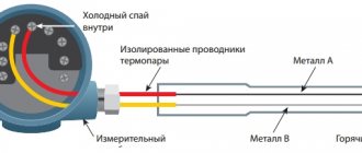
The thermocouple circuit, its design, as well as the principle of operation are significantly different from a resistance thermometer; we will tell you about this in simple words. For the pt100 device, as well as other sensors, the operating principle is based on the compatibility between the change in metal temperature and its resistance.
The thermocouple principle is based on the different properties of two metals assembled into a single bimetallic structure. The device, connection, purpose of a thermocouple, as well as a description of the error of these devices will be discussed in a separate article.
Now it is enough to understand that a thermocouple and a TSP, for example pt100, are completely different devices that differ in operating principle.
Operating principle of the measuring device
The operation of a thermal converter is based on the property of various materials to change their electrical resistance under different temperature conditions - this parameter is called the temperature coefficient of electrical resistance.
The changed temperature entails a change in the thermal vibration of the metal crystal lattice and a change in the electrical resistance of the sensor. Thus, the higher the temperature of the sensitive sensor, the more significant the vibrations of the crystal lattice, and the higher the level of electrical resistance.
As a secondary temperature sensor, the temperature transducer needs careful calibration before starting the measurement process. This is done by measuring resistance at reference points and then plotting a time dependence on resistance. The thermal converter itself, in this case, must acquire a temperature indicator similar to the measurement environment.
The accuracy of the readings can be affected by the presence of impurities in the sensor metals and possible design defects. Their heterogeneous structure can change the resistance and the speed of reaching stationary indicators for a certain temperature.
To correctly measure temperatures, it is important to ensure proper thermal contact with the measured object.
The dimensions of the sensor should be at the minimum required level, which will eliminate the possibility of increasing the measurement period and will allow recording rapidly changing processes.
Platinum Temperature Meters
Considering the prevalence of metal sensors, it makes sense to provide a brief description of these devices in order to clearly show the comparative characteristics of various types, features, and also describe the scope of application.
In accordance with the standards of GOST 6651 2009 and IEC 60751, for working devices of this type the temperature coefficient value should be 0.00385 ° C-1, for reference devices - 0.03925 ° C-1. Measured temperature range: from -196.0°C to 600.0°C. The undoubted advantages include a high accuracy coefficient, a temperature-resistance characteristic close to linear, and stable parameters. Disadvantage: the presence of precious metals increases the cost of the structure. It should be noted that modern technologies make it possible to minimize the content of this metal, which makes it possible to reduce the cost of products.
The main area of application is temperature control of various technological processes. For example, such a device can be installed in a pipeline in which the density of the working medium strongly depends on temperature. In this case, the readings of the vortex flow meter are corrected with information about the temperature of the working medium.
Thermal converter sensor TSP 5071 produced by Elemer
Sources of uncertainty in on-site temperature measurements
The new standard GOST R 8.625-2006 provides rules for rejecting a resistance thermometer by the consumer. They established that a thermometer can only be rejected if the deviation of the thermometer’s resistance from the NSX lies completely outside the range due to the expanded uncertainty of temperature measurement under operating conditions. Therefore, the problem of assessing the uncertainty that arises when measuring temperature at an object becomes very relevant. Sources of uncertainty in temperature measurement with an industrial resistance thermometer can be divided into sources associated with the physical operating conditions of the vehicle and electrical signal conversion:
– heat-conducting properties of this thermometer design and mounting elements; – transfer of heat by radiation into the environment; – heat capacity of the temperature sensor; – rate of change of measured temperature; – current leakage (grounding quality); – electrical noise; – accuracy of the meter or signal converter.
Nickel resistance thermometers
The temperature coefficient (hereinafter referred to as TC) for this type of measuring devices is the highest - 0.00617 ° C-1. The range of measured temperatures is also significantly narrower than that of platinum SEs (from -60.0°C to 180.0°C). The main advantage of these devices is the high level of the output signal. During operation, one should take into account the feature associated with the heating temperature approaching the Curie point (352.0°C), which causes a significant change in parameters due to unpredictable hysteresis.
These devices are practically not used, since in most cases they can be replaced by devices with copper sensitive elements, which are significantly cheaper and more technologically advanced (easier to manufacture).
Main parameters of thermistors
When choosing a part, it is important to focus on its indicators and characteristics, which vary depending on the type, manufacturer, source material and other indicators.
When choosing a product, you need to find out the main parameters and determine whether they are suitable for solving the task or not.
Thermistor parameters:
- DIMENSIONS. When purchasing, you need to be sure that the part is the right size and will fit on the board (in the circuit).
- RESISTANCES RT and RT. Parameters are measured in Ohms and are indicated in relation to the current temperature in degrees Celsius or Kelvin. If the part is designed to operate at temperatures from -100 to +200 degrees Celsius, the temperature regime for the environment is assumed to be 20-25 degrees Celsius.
- TIME CONSTANT Τ (SEC). The parameter reflects thermal inertia. The calculation takes into account the time required to change the temperature of the thermal resistor by 63% of the difference in t of the part and the surrounding air. In most cases, this parameter is taken equal to 100 degrees Celsius.
- TCS (% per degree Celsius). As a rule, this indicator is prescribed for the same temperature t as the cold resistance. In such a situation, other numbers are used in the designation - at.
- Dissipation power Pmax (maximum permissible parameter), W. Based on this indicator, one can judge the limit before which no irreversible changes occur in the semiconductor (the parameters remain the same). In this case, the temperature tmax cannot be exceeded when Pmax is reached.
- Temperature tmax is the maximum permissible parameter at which the characteristics of the thermistor remain unchanged for a long time (at the level set by the manufacturer).
- Energy sensitivity coefficient (measured in W/percent*R). Designation - G. The indicator reflects the power that must be dissipated on the part to reduce the R parameter by one percent.
- Dissipation coefficient (measured in Watts per degree Celsius). Symbol - H. The parameter reflects the power that is dissipated by the thermal resistor when the temperature conditions of the part and the surrounding air differ by one degree.
The coefficients discussed above (G and H) depend on the characteristics of the semiconductor used and the characteristics of heat exchange between the product and its environment. The parameters are related to each other through a special formula - G=H/100a.
- Heat capacity (measured in Joules per degree Celsius). Symbol - C. The indicator reflects the amount of heat (energy) required to heat the thermistor by one degree.
Some of the parameters discussed are related to each other. In particular, the time constant τ is equal to the ratio between the heat capacity and the dissipation coefficient.
When purchasing a positron, in addition to the above parameters, you need to take into account the range of positive temperature resistance and the factor of change in R in the positive TCR sector.
Copper sensors (TCM)
TC of copper measuring instruments is 0.00428°C-1, the range of measured temperatures is slightly narrower than that of nickel analogues (from -50.0°C to 150°C). The undoubted advantages of copper meters include their relatively low cost and the temperature-resistance characteristic that is closest to linear. But, the narrow range of measured temperatures and low resistivity parameters significantly limit the scope of application of TCM thermal converters.
Appearance of thermal converter TSM 1088 1
But, nevertheless, it is too early to write off copper sensors; there are many examples of successful implementations, for example, TXA Metran 2700, which is intended for various types of industry, but is also successfully used in housing and communal services.
Considering that platinum thermistors are most in demand, we will consider options for their design.
Classification by temperature triggering
Thermistors differ in the temperature to which they respond when triggered. From this position, the following types of parts are distinguished:
- LOW TEMPERATURE. Such elements operate at temperatures below 170 Kelvin (minus 1020C). 1 Kelvin = minus 272.150C.
- MEDIUM TEMPERATURE. Here the operating range is higher and lies between 170 and 510 Kelvin.
- HIGH TEMPERATURE. Thermistors of this class operate at temperatures from 570 Kelvin.
- SEPARATE CLASS. An individual group of high-temperature thermal resistors operating in the range from 900 to 1300 K will also be highlighted.
Regardless of the type (posistors, thermistors), thermistors can operate in different temperature conditions and external conditions. When operating under conditions of frequent temperature changes, the initial parameters of the part may change.
We are talking about two parameters - the resistance of the part at room temperature and the resistance coefficient.
Typical designs of platinum thermal resistances
The most widely used version of the SE in PTS is called a “stress-free spiral”; among foreign manufacturers it goes by the term “Strain free”. A simplified version of this design is presented below.
Strain free design
Designations:
- A – Terminals of the thermoelectric element.
- B – Protective housing.
- C – Spiral made of platinum wire.
- D – Fine filler.
- E – Glaze that seals the SE.
As can be seen from the figure, four spirals of platinum wire are placed in special channels, which are then filled with fine filler. The role of the latter is aluminum oxide (Al2O3), purified from impurities. The filler provides insulation between the turns of the wire, and also acts as a shock absorber during vibrations or when it expands due to heating. A special glaze is used to seal the holes in the protective housing.
In practice, there are many variations of the standard design, the differences may be in design, sealing material and sizes of the main components.
Performing Hollow Annulus.
This type of design is relatively new; it was developed for use in the nuclear industry, as well as at facilities of special importance. In other areas, sensors of this type are practically not used, the main reason for this is the high cost of the products. Distinctive features: high reliability and stable performance. Let's give an example of such a construction.
Sample performance of "Hollow Annulus"
Designations:
- A – Conclusions from the SE.
- B – Isolation of SE terminals.
- C – Insulating fine filler.
- D – Sensor protective housing.
- E – Platinum wire.
- F – Metal tube.
The SE of this design is a metal tube (hollow cylinder), covered with a layer of insulation, on top of which a platinum wire is wound. The cylinder material is an alloy with a temperature coefficient close to platinum. The insulating coating (Al2O3) is applied by hot spraying. The assembled SE is placed in a protective housing, after which it is sealed.
This design is characterized by low inertia; it can be in the range from 350.0 milliseconds to 11.0 seconds, depending on whether a submersible or mounted SE is used.
Film version (Thin film).
The main difference from previous types is that platinum is sprayed in a thin layer (several microns thick) onto a ceramic or plastic base. A glass, epoxy or plastic protective coating is applied over the spray.
Miniature film sensor
This is the most common type of design, the main advantages of which are low cost and small dimensions. In addition, film sensors have low inertia and relatively high internal resistance. The latter almost completely neutralizes the impact of the terminal resistance on the instrument readings (thermal resistance tables can be found on the Internet).
As for stability, it is inferior to wire sensors, but it should be borne in mind that film technology is improving year by year, and the progress is quite noticeable.
Glass insulated spiral.
In some expensive vehicles, the platinum wire is coated with glass insulation. This design ensures complete sealing of the SE and increases moisture resistance, but narrows the range of measured temperatures.
Thermal converter device
The design of this device consists of a temperature-sensitive element (one or more) and internal connecting wires, which are located in a sealed protective housing, and complemented by external leads for connection to the measuring device.
The sensitive element of the device is a resistor made of metal wire or film, and having leads for connecting connecting wires.
Tolerance class
According to current standards, a certain deviation from the linear temperature-resistance characteristic is allowed. Below is a table of accuracy class correspondence.
Table 1. Tolerance classes.
| Accuracy class | Tolerance standards °C |t | | Temperature measurement range | |||
| Platinum sensors | Copper | Nickel | |||
| Wire | Film | ||||
| A.A. | ±0,10+0,0017 | -50°C…250°C | -50°C…150°C | x | x |
| A | ±0,15+0,002 | -100°C…450°C | -30°C…300°C | -50°C…120°C | x |
| B | ±0,30+0,005 | -196°C…660°C | -50°C…500°C | -50°C…200°C | X |
| WITH | ±0,60+0,01 | -196°C…660°C | -50°C…600°C | -180°C…200°C | -60°C…180°C |
The error shown in the table corresponds to current standards.
TSM/TSP switching circuits
There are three connection options:
- 2 wire (see A in Fig. 7), this simplest method is used in cases where the accuracy of the results is not critical. An additional error is created by the nominal resistance of the conductors with which the sensor is connected. Please note that for accuracy classes A and AA this connection scheme is unacceptable.
Figure 7. Two-wire, three-wire and four-wire resistance thermometer connection circuit - 3-wire (B) . This option has higher accuracy than the 2-wire connection option. This is due to the fact that it becomes possible to measure the resistance of the installation wires to take into account their influence.
- 4-wire . This option allows you to completely eliminate the impact of the resistance of the installation wires on the measurement results.
In measuring instruments, the vehicle is usually connected in a bridge circuit.
Example of bridge connection of a secondary device (pt100) for air temperature measurement
Please note that under rhp. in the electrical diagram, the resistance of the communication lines, that is, the wires with which the sensor is connected, is implied.
Menu
Introduction
Temperature is one of the most frequently measured physical quantities.
Problems of temperature measurement and control occur in almost all areas of human activity. Temperature control systems are used to maintain microclimate and in various household appliances, where the basic requirement is their availability. Precision temperature control in agriculture is necessary for growing greenhouse crops. In the chemical industry and metallurgy, temperature control of highly aggressive media in ranges of several thousand degrees is often required. In production, violations of the technological process associated with the controlled temperature exceeding acceptable limits can lead to the release of a batch of defective goods. In medicine, an error in temperature measurement can cost a patient's health and even a human life. The life of the entire population of our planet depends on the quality of temperature control in the nuclear industry, in particular during the casting of reactor vessels. It is obvious that such diverse requirements, both in terms of range and accuracy, and in terms of the type of design and reliability of measuring systems, have given rise over the years to a wide variety of methods and means used for temperature measurement and control.
The key element of any temperature measurement and control system is the primary measuring transducer (sensing element). The performance of the entire system as a whole largely depends on its accuracy and other basic parameters. There are various types of temperature sensors, the most common among them are thermocouples, semiconductor thermistors and resistance thermometers [].
Resistance thermometers
A resistance thermometer (RT) consists of one or more temperature-sensitive elements and internal connecting wires placed in a sealed protective housing, as well as external terminals and leads intended for connection to the measuring device. The sensitive element (SE) of a resistance thermometer is a resistor made of metal wire or film, with leads for attaching connecting wires, which has a known dependence of electrical resistance on temperature [].
In practice, the term “resistance thermometer” refers to both a sealed sensor in a metal or ceramic housing with an external connector for connection to measuring instruments, and the sensing element itself, which can be manufactured in a housing with wire leads or in an SMD design for surface mounting.
The main advantages of TCs compared to other types of temperature sensors are their high accuracy, wide range of operating temperatures, small size, resistance to vibration, linearity of the nominal static characteristic and a relatively high value of the temperature coefficient of resistance (TCR). The main materials for the manufacture of SE TS are platinum, copper, nickel and their alloys. In practice, platinum resistance thermometers (PRTs) with different purities of platinum are more often used, which have the highest stability of characteristics, resistance to aggressive environments and a wide range of operating temperatures (Table 1).
Table 1. Comparative characteristics of common types of temperature sensors
| Temperature sensor type | Main advantages | Main disadvantages | Main Applications |
| Resistance thermometers | High linearity of the nominal static characteristic Wide range of operating temperatures High stability of the main parameters Resistance to aggressive media Relatively low cost | Need for external circuitry for excitation | Widely used in both relatively inexpensive and precision temperature measurement and control systems |
| Semiconductor thermistors | Low cost and availability High temperature coefficient of resistance | Requirement for an external circuit for excitation High non-linearity of the nominal static characteristic Low stability of the main parameters | Designed for use in inexpensive devices with low requirements for measurement accuracy, in simple systems of one- and two-threshold temperature control, or for organizing temperature control in secondary components of complex electronic equipment |
| Thermocouple | Widest operating temperature range High repeatability High performance | Need for reference junction compensation Low output voltage Need to use large structures for reference junction compensation to achieve high measurement accuracy | Widely used in low-cost devices with “electronic” compensation of the reference junction with low measurement accuracy. Used in ultra-precision measuring systems 0.01...0.25 °C with compensation of the reference junction using a Dewar vessel or specialized thermostats |
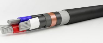
Based on the design of the sensitive element, film and wire resistance thermometers are distinguished. As a rule, copper and nickel vehicles are made of wire (Fig. 1), and platinum ones can be either wire or film. The latter have less sensitivity to vibrations, but are designed to operate in a narrower temperature range (Fig. 2). According to their intended purpose, they distinguish between working and reference resistance thermometers; the parameters of both groups of TCs are regulated by the relevant standards.
Rice. 1. Wire resistance thermometer design
Rice. 2. Film resistance thermometer
Local and international standards for vehicles
There are many standards for working industrial vehicles that have local or interstate status. Among the most common are the “European” IEC 60751 (DIN/IEC EN 60 751) and the “North American” ASTM 1137. Many others, such as DIN 43760, BS 1904 (1984) and SAMA RC-4 (1966), despite their occasional references in the literature are considered obsolete. The IEC 60751 standard is one of the most widespread and regulates the characteristics of PTS with a nominal resistance of 100 Ohms at a temperature of 0 °C and a temperature coefficient of resistance α = 0.00385 °C–1 []. ASTM E1137/E1137M-08 covers the requirements for PRTs for industrial applications with α = 0.00385 °C–1 in the temperature range from 0 to +100 °C and a nominal resistance of 100 ohms at 0 °C [].
In Russia, until 01/01/2011, the standard GOST R 8.625-2006 “Resistance thermometers made of platinum, copper and nickel” was in force, which corresponds to the international standard IEC 60751 (2008) in terms of determining the dependence of the resistance value on temperature and tolerances for platinum SEs and TCs with temperature resistance coefficient α = 0.00385 °C–1.
The standard establishes general technical requirements and test methods for technical resistance thermometers whose sensing elements are made of platinum, copper and nickel. These instruments are designed to measure temperatures from –200 to +850 °C or part of this range []. Since 2011, a new interstate standard GOST 6651-2009 “Resistance thermal converters made of platinum, copper and nickel” has appeared in Russia. General technical requirements and test methods", which was created on the basis of GOST R 8.625-2006. Unfortunately, at the time the material was submitted to the editor, the text of the new standard was still not available. However, the draft of this standard is available on the Internet and does not contain significant differences compared to GOST R 8.625-2006 []. Therefore, later in the article the main provisions of the GOST R 8.625-2006 standard are chosen as the basis.
Differences in standards in different regions of the world have led to differences in some basic vehicle parameters among manufacturers. For example, different standards use different TCR values: α = 0.003923 °C–1 (SAMA), α = 0.00385 °C–1 (DIN/IEC EN 60 751), α = 0.003902 °C–1 (US IS), α = 0.003916 °C–1 (JIS), etc. Therefore, in order to avoid errors in calculations during design, it is important to take into account the provisions of the standard against which the characteristics of the selected resistance thermometer were normalized.
Basic parameters of the vehicle
The main parameters that determine the areas of application and connection circuits of resistance thermometers are the temperature coefficient of the resistance thermometer, the nominal resistance, the range of measured temperatures and the nominal static characteristic of the vehicle.
Temperature coefficient of resistance thermometer
The temperature coefficient of a resistance thermometer characterizes the change in resistance value as a function of temperature:
α = (R100–R0)/(R100×100),
where R100, R0 are the vehicle resistance values from the nominal static characteristic (NSC) at 100 and 0 °C, respectively, rounded to the fifth decimal place. As noted earlier, different standards set different TCS values. To increase compatibility, GOST R 8.625-2006 considers two values: α = 0.00391 °C–1 and α = 0.00385 °C–1 (corresponds to IEC 60751).
Nominal resistance of the vehicle
The nominal resistance of the vehicle is the resistance normalized by the manufacturer at 0 °C, rounded to whole units, selected from the range: 10; 50; 100; 500; 1000 Ohm []. There are vehicles with other values of nominal resistance, but currently the most widespread are PTS with a nominal resistance of 100 Ohms at 0 °C. At the same time, there is a tendency to use vehicles with a nominal resistance value of up to 1 kOhm and even 10 kOhm. Measuring systems that use devices with a high nominal resistance have additional advantages, an important one of which is the reduction in the influence of the length of the connecting wires of the vehicle on the accuracy of measurements.
Maximum vehicle measurement range
The maximum measuring range of the vehicle depends not only on the properties of the material from which the sensitive element is made, but also on design features, such as the method and material of insulation, connecting elements, etc. Despite the fact that the domestic standard applies to the range from –200 to +850 °C [], there are resistance thermometers with operating temperature limits that go beyond this. For most industrial working vehicles, the measurement range is from –196 to +660 °C (platinum), from –50 to +200 °C (copper) and from –60 to +180 °C (nickel).
Table 2 shows the tolerance classes of resistance thermometers corresponding to GOST R 8.625-2006 [].
Table 2. Tolerance classes and measurement ranges for resistance thermometers and sensitive elements
| Tolerance class | Tolerance, °С | Measuring range, °С | |||
| Platinum TS, CHE | Copper TS, ChE | Nickel TS, ChE | |||
| wire | film | ||||
| AA W 0.1 F 0.1 | ±(0.1+0.0017 |t|*) | –50…+250 | –50…+250 | – | – |
| AW 0.15 F 0.15 | ±(0.15+0.002 |t|) | –100…+450 | –50…+450 | –50…+120 | – |
| BW 0.3 F 0.3 | ±(0.3+0.005 |t|) | –196…+660 | –50…+600 | –50…+200 | – |
| CW 0.6 F 0.6 | ±(0.6+0.01 |t|) | –196…+660 | –50…+600 | –180…+200 | –60…+180 |
Note.
* |t| — absolute value of temperature, °C, without taking into account the sign.
In practice, vehicles standardized by two additional accuracy classes are sometimes used; they are usually called “1/10 DIN” and “1/3 DIN”, which means, respectively, 1/10 (±0.03 °C) and 1/3 (±0.1 °C) from class B at 0 °C.
Nominal static characteristic
The nominal static characteristic (NSC) represents the dependence of the resistance of the vehicle on temperature. For PTS, this dependence has the form (Callendar van Dusen equation):
- in the range from –200 to 0 °C:
Rt = R0[1+A×t+B×t2+С(t–100)t3]; - in the range from 0 to +850 °C:
Rt = R0(1+A×t+B×t2),where Rt is the resistance of the vehicle, Ohm, at a temperature of t °C; R0 - resistance of the vehicle, Ohm, at a temperature of 0 °C; A, B and C are coefficients obtained empirically.
The values of coefficients A, B and C are different for different temperature coefficients of resistance:
- α = 0.00385 °C–1: A = 3.9083×10⁻³ °C–1, B = –5.775×10⁻⁷ °C–2, C = –4.183×10⁻¹² °C–4;
- α = 0.00391 °C–1: A = 3.969×10⁻³ °C–1, B = –5.841×10⁻⁷ °C–2, C = –4.33×10⁻¹² °C–4.
For copper and nickel resistance thermometers, there are similar calculated dependencies that can be found in the reference literature [].
The nominal static characteristic for a resistance thermometer can be presented in the form of a table, which indicates the temperature values and the corresponding resistance values of the vehicle, or in graphical form. In Fig. Figure 3 shows the dependence of the resistance value of a Pt100 platinum thermometer (NSH) on temperature, constructed using the Callendar van Dusen equation. The blue line indicates the dependence obtained using coefficients A, B and C. The red line is the characteristic obtained as a result of linear approximation with B = C = 0 [].
Rice. 3. Dependence of PTS resistance (Pt100) on temperature
The magnitude of the error arising from the linear approximation of the vehicle characteristics (B = C = 0) can be estimated based on the graph shown in Fig. 4.
Rice. 4. Error in linear approximation of the PTS characteristic (Pt100)
Information in Fig. 4 helps to make the right decision about the advisability of precision linearization of the PTS characteristic, which may require the use of additional components, computing resources of the system processor, or be limited to linear approximation.
Connection circuits for resistance thermometers
The simplest circuit for connecting a resistance thermometer is a voltage divider (Fig. 5). Here TC Rt is its arm, and a source with voltage Upit ensures the flow of electric current in the divider circuit. The voltage drop across the vehicle Ut depends on the value of its resistance, and therefore on the ambient temperature tamb.
Rice. 5. Temperature measurement circuit using a device based on a voltage divider
The accuracy of measurements in the circuit (Fig. 5) will depend on the accuracy and stability of the characteristics of the vehicle Rt, the reference resistor Rop and the voltage source Upit. In order to reduce measurement error, a precision, highly stable resistor Rop and a stabilized reference voltage source should be used.
Another negative factor is the effect of self-heating of the resistance thermometer: the flow of a relatively high current in the electrical circuit (a few to tens of milliamps) can lead to additional heat generation on the vehicle, its heating and, as a result, to a sharp decrease in the accuracy of measurements.
As an example, let us estimate the temperature deviation as a result of self-heating for a highly stable precision platinum resistance thermometer Rt of the PTS 0603 series (Vishay) with a nominal resistance R0 = 100 Ohm []. Let us choose, for clarity, a reference resistor with a nominal value of Rop = 1000 Ohms. Let the value at the output of the stabilized voltage source be VDD = +5 V. The total resistance of the voltage divider circuit: Rtot = R0+Rop = 100+1000 = 1100 Ohms. Then the amount of current flowing through the divider will be equal to: IDD = VDD/Rtot = 5/1100 = 0.0045 A. The power dissipated by the PTS will be approximately: P = IDD2×R0 = 0.0021 W (2.1 mW ). According to the technical documentation for the PTS 0603 series, its self-heating value is 0.9 K/mW in the absence of forced ventilation. Thus, the increase in the temperature of this PTS in our example can reach a value of Tload = 0.9 × 2.1 = 1.9 K. Obviously, for tasks of measuring temperature with an accuracy of the order of tenths of a degree, this is more than an acceptable error!
The magnitude of the measuring current must be such that self-heating does not lead to the vehicle parameters going beyond the tolerance limits. The increase in its resistance due to self-heating should not exceed 20% of the tolerance. It is recommended to excite DC circuits for vehicles with a nominal resistance of 100 Ohms with a measuring current of 1 mA or less []. To minimize the impact of this effect, it is necessary to select a reference resistor with a high nominal resistance value and/or a source with a lower supply voltage. Despite the fact that this will lead to a decrease in the sensitivity of the circuit, the use of a vehicle with a relatively high TCR and a modern element base for signal normalization makes it possible to compensate for this shortcoming.
In Fig. Figure 6 shows an example of a practical implementation of a circuit based on a voltage divider using a stabilized reference voltage source.
Rice. 6. The simplest connection diagram for a Pt100 resistance thermometer
The MAX6126A41 reference voltage source with precision resistor R1 provides TC excitation with a current of approximately 200 μA at 0 °C []. The gain of the MAX9617 zero-drift operational amplifier is set by the MAX5491WA30000 precision divider and is equal to Ku = 31 [10, 11]. The output voltage of the circuit is 616 mV at 0 °C. The change in output voltage is 2.37 mV/°C. Precision platinum resistance thermometers of the PTS and PTL series [, ] can be used as Pt100, and resistors of the PHR0805 or P0805 series produced by Vishay can be used as a highly stable resistor R1, here and in other circuit solutions in this article [12, 13].
The main disadvantages of the switching circuit (Fig. 6) are the high dependence of the excitation current on temperature, which causes additional nonlinearity, increasing the measurement error and the complexity of organizing a remote connection of the vehicle, since the resistance of the connecting wires in a two-wire circuit will have a noticeable effect on the measurement results. Considering the relatively low ratings of the devices used, it is obvious that even parasitic resistances of hundreds of mOhms will cause unacceptable errors in temperature measurements. According to GOST R 8.625-2006, the use of a two-wire circuit is not allowed for vehicles of classes AA and A (Table 2).
Despite the existing disadvantages, the circuit can be used to organize simple temperature measurement systems, the advantages of which are low cost of implementation, small overall dimensions and, most importantly, the short distance of the resistance thermometer from the signal standardization circuit.
In the case of a remote connection of the vehicle, the length of the connecting wires will affect the accuracy of the measurements, since the measuring current will cause an additional voltage drop, directly proportional, according to Ohm's law, to the resistance value. Since the resistance of conductors depends on their length, increasing the distance to the sensor will require the use of more expensive connecting conductors or adjustments to the approach to constructing the measuring system.
If it is necessary to connect a remotely located resistance thermometer, it is more advisable to use a 4-wire “Kelvin” circuit, in which the measuring current flows through one pair, and the measurements themselves are made using the second pair of connecting wires. To achieve high measurement accuracy, it is necessary to use amplifiers with high input impedance and low input current.
This principle is implemented in the example in Fig. 7. Platinum resistance thermometer Pt100 is connected in a 4-wire circuit. Increased linearity is achieved by excitation of the TC with a stabilized current source (198 μA), the circuit of which is implemented using a MAX6126A25 reference voltage source and resistor R2. The MAX9617 operational amplifier eliminates the influence of self-current consumption of the reference voltage source. The MAX4208 instrumentation amplifier has 1 pA input current and 135 dB common mode rejection ratio []. Resistor R1 is designed to shift the signal level relative to the common bus for more effective suppression of powerful common-mode interference. The MAX4208 instrumentation amplifier's gain of Ku = 31 is set using the MAX5491WA30000 precision divider. A somewhat non-standard way of setting the gain of an instrumentation amplifier is due to the uniqueness of its architecture []. The output voltage of the circuit will be 15.5 mV at a temperature of –250 °C, 615 mV at 0 °C and +2.4 V at 850 °C.
Rice. 7. Wiring diagram for remote Pt100 resistance thermometer using a current source
The use of modern analog-to-digital converters (ADCs) with a differential connection of the input signal source and the reference voltage source allows not only to obtain a digital signal at the output, ready for input into the microcontroller, but also to simplify the connection of resistance thermometers. In Fig. Figure 8 shows a diagram of a precision temperature meter based on an ADC.
Rice. 8. Precision temperature meter
The MAX11201B low-noise, 24-bit sigma-delta ADC allows you to connect an RTD without the need for precision current or voltage sources using the low-cost, low-noise, low-dropout MAX8510 (LDO) regulator [, ]. The voltage drop across precision resistor R5 provides a reference voltage to the ADC. Since the measuring current flowing through resistor R5 also excites the resistance thermometer, any fluctuations in the current value will be completely compensated. Resistors R1 and R6 ensure normal operation of the buffer amplifiers built into the ADC. They limit the absolute value of the input and reference voltages relative to ground within the range of +150 mV to (AVdd–150) mV.
In order to reduce the number of connecting wires for connecting the thermal resistance to three, a precision current mirror can be introduced into the circuit using the MAX9617 operational amplifier and the MMBTA14 transistor (Fig. 9). A matched pair of resistors PRAHR182I2-750RFW will ensure equality of currents I1 and I2 with an accuracy of 0.05%, thereby compensating for the voltage drop on the connecting wires []. The latter must be of the same type, the same length and cross-section. Currently, various specialized shielded cables are produced for connecting resistance thermometers in 2-, 3- and 4-wire circuits.
Rice. 9. Precision temperature meter with 3-wire resistance thermometer connection
For industrial applications, the MMBTA14 bipolar compound transistor is more preferable than the field-effect transistor, especially when operating at high temperatures. For insulated gate transistors (MOSFETs), the gate leakage current doubles with every 8°C increase in temperature and can reach several tens of nA. Thus, the current mirror error caused by the driving current of a bipolar transistor can be less than that of an insulated gate field effect transistor.
Conclusion
One of the ways to increase the accuracy of measurements using TS is their calibration to obtain individual coefficients of the dependence of the resistance value on temperature. The obtained coefficients can, for example, be stored in the memory of a digital measuring system and an appropriate correction can be made to the measurement result. However, this method may be acceptable in small-scale production and is practically not feasible in mass production due to the high complexity of the calibration procedure itself. In this case, a more effective solution may be to use precision resistance thermometers.
However, the very fact of using precision vehicles cannot guarantee high accuracy of the system as a whole. In this case, the adequacy of the chosen circuit for switching on the vehicle to the problem being solved plays an important role. In addition, it is necessary to take into account the influence of factors such as the length and quality of connecting wires and connectors, ensuring electromagnetic compatibility through effective shielding, filtering, proper arrangement of elements and printed circuit board layout. There is also a very specific, but noticeable source of errors, such as the effect of the crystal temperature on the ADC conversion results, the impact of which can be taken into account by introducing an additional sensor into the system to measure the crystal temperature.
As practice shows, only such an integrated approach, taking into account various aspects of design, makes it possible to create systems that are balanced in terms of accuracy and cost and have competitive advantages in the market of modern electronic equipment.
Literature
- GOST R 8.625-2006 “Resistance thermometers made of platinum, copper and nickel.” M.: Standartinform, 2006.
- IEC EN 60 751. Industrial Platinum Resistance Thermometers and Platinum temperature sensors. Edition 2.0. International Electrotechnical Commission.
- ASTM E1137/E1137M-08. Standard Specification for Industrial Platinum Resistance Thermometers.
- GOST 6651-2009 “Resistance thermometers made of platinum, copper and nickel. General technical requirements and test methods". Draft standard. Information portal https://www.temperatures.ru
- Industrial electronics. Developer's Guide. 2010. Issue. 1. Maxim Integrated Products. https://www.symmetron.ru
- Thermal Management Handbook. Maxim Integrated Products. https://www.maxim-ic.com
- Platinum SMD Flat Chip Temperature Sensor. PTS Series. Technical Datasheet, Rev. 03/11/2011. https://www.vishay.com
- Leaded Platinum Temperature Sensor. PTL Series. Technical Datasheet, Rev. 03/11/2011. https://www.vishay.com
- MAX6126: Ultra High Precision, Ultra Low Noise, Series Voltage Reference. Technical Datasheet, Rev.5, 12.2010. https://www.maxim-ic.com
- MAX9617: Single/Dual SC70, Zero-Drift, High-Efficiency, 1.5MHz Op Amps with RRIO. Technical Datasheet, Rev.4, 02.2011. https://www.maxim-ic.com
- MAX5491: Precision-Matched Resistor-Divider in SOT23. Technical Datasheet, Rev.3, 12.2004. https://www.maxim-ic.com
- PHR Series. ESCC 4001/023 Qualified High Precision (5 ppm, 0.01%), Thin Film Chip Resistors. Technical Datasheet, Rev. 29.11.2010. https://www.vishay.com
- P Series. High Precision Wraparound - Wide Ohmic Value Range Thin Film Chip Resistors. Technical Datasheet, Rev. 02/14/2011. https://www.vishay.com
- MAX4208: Ultra-Low Offset/Drift, Precision Instrumentation Amplifiers with REF Buffer. Technical Datasheet, Rev.1, 04.2009. https://www.maxim-ic.com
- MAX11201:24-bit, Single-Channel, Ultra-Low-Power, Delta Sigma ADC with 2-Wire Serial Interface. Technical Datasheet, Rev.0, 06.2010. https://www.maxim-ic.com
- MAX8510: Ultra-Low-Noise, High PSRR, Low-Dropout, 120 mA Linear Regulators. Technical Datasheet, Rev.3, 05.2006. https://www.maxim-ic.com
- PRAHR PRA HR (CNW HR) Series. ESA Qualified High Precision Thin Film Chip Resistor Arrays. Technical Datasheet, Rev. 04.10.2010. https://www.vishay.com
Service
Information about maintenance of the temperature sensor is indicated in the device passport or operating instructions; typical faults and methods for their repair, the recommended cable length for connection, as well as other useful information are also given there.
Resistance thermometers do not require special maintenance; the tasks of the maintenance personnel include:
- Checking the conditions in which the sensor is operated.
- External inspection for structural integrity and cable connections, checking the movement of the movable fitting (if any).
- In addition, the presence of seals is checked.
- Grounding is checked.
Such inspection should be carried out once a month or more often.
In addition, devices must be verified using a reference sensor, for example, ETS 100.
Platinum Reference PTS (ETS 100 Sensor)
To calibrate sensors, special tables are used; one of them for thermal resistance pt100 is given as an example. We will not present the calibration method itself; its description is easy to find on the Internet.
Calibration table for thermistor pt100 (fragment, without indicating measurement calibration limits)
As for the verification method for standard platinum sensors, it should be carried out at special reference points.
How to connect
The principle of connecting thermistors is simple (using the example of Arduino). This requires a circuit board, a part, and a 10k ohm resistor. Since the product has high resistance, this parameter for conductors does not affect the final result.
One resistance pin is connected to the 5V pin and the other is connected to the thermistor pin.
The second tap of the thermistor must be connected to ground. The center of the two resistors is connected to the “Analog 0” pin.
<