Disconnector is a medium voltage (6-10 kV) switching device designed to disconnect an electrical circuit in the absence of current or with insignificant current (for example, no-load current of transformers).
Disconnectors are used to provide safety during equipment repair or maintenance by creating a visible break in the electrical circuit. Also, disconnectors are used to switch from one bus to another, in electrical installations with several buses.
The disconnectors are equipped with an on/off position lock and grounding blades that prevent the supply of voltage to the disconnected section of the network.
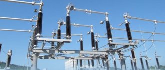
Outdoor disconnectors are designed for installation on power transmission line supports, so they operate in the most severe conditions, including rain, thunderstorms, snow, and ice.
Outdoor installation disconnectors of the RLND, RLK series are designed to turn on and off de-energized sections of a high-voltage electrical circuit, no-load currents of transformers, charging currents of overhead lines, as well as grounding of disconnected sections of the circuit using built-in grounding switches.
Currently, the most popular are two types of external disconnectors: rotary (RLND) and swing (RLK).
Select an outdoor disconnector...
Column disconnectors RLND
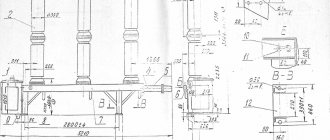
A linear disconnector for outdoor installation of a two-column type, RLND series, is the simplest budget type of disconnector for outdoor installation.
The disconnector is made in the form of a three-pole (on one frame) device, horizontally rotating type, each pole of which has one movable and one fixed insulator that carries the current-carrying system. Opening connections of the main and grounding circuits are made through lamellar contacts, the contact pressure in which is created by springs.
The RLND disconnector is designed:
- to create a visible break in the electrical circuit in order to ensure safe maintenance of electrical equipment;
- for switching on and off energized de-energized sections of the high voltage circuit;
- for grounding disconnected areas using stationary ground electrodes;
- for turning off and turning on the no-load current of transformers.
The RLND disconnector is equipped with a PRNZ-10 drive for manually switching on and off the main and grounding blades of the disconnector.
Terms of Use:
- ambient temperature from -40° C to +40° C;
- installation height above sea level - no more than 1000 m;
- wind speed no more than 40 m/s in the absence of ice, up to 15 m/s with a permissible ice wall of no more than 10 mm;
- ice wall thickness 10 mm;
- seismicity of the area is up to 7 points.
Symbol for disconnector RLND
RLND-1(2)-10(.II).IV/(400)630 UHL1
- P – disconnector;
- L – linear;
- N – outdoor installation;
- D – two-column;
- 1, 2 – location of grounding blades (1 – on the side of the rotary insulator, 2 – on both sides);
- 10 – rated voltage, kV;
- II, IV - degree of atmospheric pollution (II - for porcelain insulators, IV - for polymer insulators);
- 400, 630 – rated current, A;
- UHL1 – climatic version and placement category.
Technical characteristics of RLND disconnectors
| Parameter | Meaning |
| Rated voltage, kV | 10 |
| Highest operating voltage, kV | 12 |
| Rated current, A | (400)630 |
| Rated thermal current, kA | 10 |
| Rated current of electrodynamic resistance, kA | 25 |
| Leakage distance of external insulation, m | 0,23 |
| Permissible wire tension applied to fixed insulators, N, no more | 200 |
| Weight, kg | 30 |
Select disconnector RLND...
Design
RG series disconnectors for voltages of 110 and 220 kV with a normal insulation level in accordance with GOST 1516.3, as well as disconnectors with increased electrical strength, are made with improved performance properties. The connecting dimensions of the new disconnectors were selected taking into account the possibility of installing them on existing supporting structures of disconnectors of the RDZ series.
Disconnectors are two-column devices with contact blades rotating in a horizontal plane. Disconnectors consist of a main current-carrying system, rotary support insulation, a supporting frame and grounding conductors.
The contact blades of the disconnectors are made of copper bars (110 kV) or pipes (220 kV), to which bronze alloy lamellas are attached. The output contacts are made with transition contact rollers and are hermetically sealed. This ensures stable contact pressure throughout the entire service life and low operating forces on the manual drive handle. The contact surfaces of the detachable and output contacts are coated with silver.
The disconnectors are equipped with high-strength porcelain or polymer insulators.
The main contact blades of disconnectors and grounding switches can be controlled by both electric motor drives PD-14UHL1 and manual drives PRG-6UHL1. PD-14UHL1 drives are equipped with switching units based on microswitches. All drives are equipped with a modernized electromagnetic locking type ZB-1M with an electromagnetic key KEZ-1M and a key KM-1 for emergency release.
Disconnectors and their main components are protected by Russian Federation certificates for utility models.
Rocker type disconnectors RLK
The RLK series disconnector is made in the form of a three-pole swing-type device, each plus of which has two fixed columns mounted on the frame of the disconnector, and one movable column mounted on a rotary bracket, which can swing in the direction of the longitudinal axis of the disconnector.
The disconnector is intended:
- to create a visible break in the electrical circuit in order to ensure safe maintenance of electrical equipment;
- for switching on and off energized de-energized sections of the high voltage circuit;
- grounding of disconnected areas using stationary ground electrodes;
- for turning off and turning on the no-load current of transformers.
The RLND disconnector is equipped with a PR-RLK drive designed for manual switching on and off of the main and grounding blades of the disconnector.
Terms of Use:
- ambient temperature from -40°С to +40°С;
- installation height above sea level - no more than 1000 m;
- wind speed no more than 40 m/s in the absence of ice, wind speed up to 15 m/s with a permissible ice wall of no more than 10 mm;
- ice wall thickness 10 mm;
- seismicity of the area is up to 7 points.
Symbol of RLC disconnector
RLC(V)-1a-(IV)-10/400(630) UHL1
- P – disconnector;
- L – linear;
- K – swing type;
- (B) – vertical installation;
- 1a, 1b, 2 – grounding blades on the side of the fixed column, on the side of the movable column, on both sides (in the absence of blades, the index is omitted);
- IV – degree of atmospheric pollution (for polymer insulators);
- 10 – rated voltage, kV;
- 400, 630 – rated current, A;
- UHL1 – climatic version and placement category.
Technical characteristics of RLC disconnectors
| Parameter | Meaning |
| Rated voltage, kV | 10 |
| Highest operating voltage, kV | 12 |
| Rated current, A | (400)630 |
| Rated thermal current, kA | 10 |
| Rated current of electrodynamic resistance, kA | 25 |
| Leakage distance of external insulation, m | 0,23 |
| Permissible wire tension applied to fixed insulators, N, no more | 200 |
| Weight, kg | 27 |
Select RLC disconnector...
Exhaust fuses-disconnectors PRVT type
Fuse-disconnectors of the PRVT-10 series are designed to protect power transformers and distribution systems from short circuits and extreme overload currents, as well as to switch on and off sections of the electrical circuit (with an isolated or grounded neutral) with the load disconnected using an operating rod.
The fuse-disconnector is made in the form of a single-pole device consisting of a porcelain insulator, at the ends of which a contact system is attached to brackets for installing a replaceable element with a fuse-link.
In case of overload and short circuit currents, the fuse link burns out, the holder of the replaceable fuse-disconnector element automatically tilts back, thereby creating a visible gap. Thus, the device performs simultaneous functions of a protective device and a disconnector.
Replaceable elements are made with two types of time-current characteristics: type “K” - fast; type “T” – slow, which allows for selectivity of protection.
The delivery set of PRVT for 3 poles includes 19 replaceable elements and 1 spare cartridge.
The design of fuse-disconnectors ensures:
- reliable fixation of the knife cartridge in the upper contact in the on position and quick tilting of the cartridge when disconnected;
- the ability to quickly and conveniently replace the element being replaced;
- reusable cartridge.
The switching life of the cartridge is at least 5 shutdowns with a total short circuit current of 6.3 kA, and reload currents are up to several dozen shutdowns.
Removal and installation of the holder of the replaced element is carried out manually using a special operational insulating rod. The rod allows you to operate in wet weather and in the rain at wind speeds of up to 15 m/s. The design of the fuse-disconnectors eliminates spontaneous operations without an operating rod. There are 2 types of rods available to choose from.
After disconnecting the line, the knife-chuck can be removed and stored by the master, which prevents unauthorized activation of the PRVT by unauthorized persons, even in the presence of a ladder.
To ensure safety during maintenance and repair work, the PRVT design is equipped with a special bolt (pin) for applying a standard portable grounding to it (with the fuses disconnected).
The poles of the fuse-disconnectors are fastened to the support on a traverse (by the bracket in the middle part of the insulator).
PRVT-10 fuse-disconnectors can be supplied with sets of mounting parts for installation on various types of VL-10 supports, as well as for upgrading existing 10/0.4 kV cabinet-type substations to a power of 25–250 kVA with PKT-101 and PKT fuses –102, directly at the site of operation of the package transformer substation.
Technical characteristics of PRVT disconnectors
| Parameter | Meaning |
| Rated voltage, kV | 10 |
| Highest operating voltage, kV | 12 |
| Rated current, A | 5-80 |
| Rated base current, A | 200 |
| Rated breaking current, kA | 6,3 |
| Leakage distance of external insulation, m | 0,32 |
| Permissible tension of wires in the horizontal direction, in the plane of the pole, N, no more | 250 |
| Weight, kg | 27 |
Select fuse-disconnector PRVT…
Purpose of load switch
Autogas load switch
Unlike a disconnector, a load switch is designed to disconnect a live line .
When energized contacts are opened or closed, an arc discharge occurs, which can melt the contacts of the load switch and thereby damage it. Therefore, it is necessary to prevent the occurrence of an arc discharge or weaken it.
To extinguish or weaken the arc discharge, the air environment between the contacts of the load switch is replaced with a safer environment. This is the main difference between a load switch and a disconnector - the contacts of the load switch are in an inert environment that prevents the development of an electric arc.
Currently, there are several options for protecting switches from electric arcs:
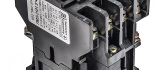
- Autogas environment is the most ingenious solution. The switch contacts are located inside a polymer casing, which, when an arc discharge occurs, begins to release gases that prevent the development of the arc. This class of switching devices is called autogas load switches. Autogas switches are the most affordable, but they can only operate at low currents, usually up to 630 A.
- Oil media is the oldest solution. In this case, the switch contacts are placed in a tank with mineral oil, which prevents the formation of an arc. Oil circuit breakers began to be used in Russia in 1925, but at present they are gradually falling out of use, giving way to vacuum circuit breakers.
- SF6 gas environment - using sulfur hexafluoride SF6 as the internal environment of the switch. Sulfur hexafluoride (SF6 gas) is colorless, non-toxic and non-flammable. It received its name due to its high electrical insulating and arc extinguishing properties, as well as its high breakdown voltage. However, due to high disposal costs, insufficient compactness of SF6 devices, as well as toxic compounds formed during their operation, manufacturers began to abandon SF6 circuit breakers in favor of vacuum circuit breakers.
- Vacuum is an ideal environment that prevents the formation of an arc discharge. The contacts in this case are located inside the vacuum boat. Representatives of this class of devices are not only the widespread vacuum switches, but also VNVR load switches, which are very similar to autogas switches, but differ from them in the presence of vacuum chambers instead of polymer suppressor chambers.
Thus, the main difference between a load switch and a disconnector is the ability to disconnect a live line by suppressing the arc discharge with an inert medium between the switch contacts.