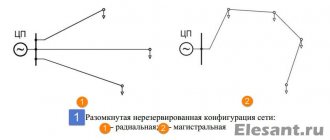
Disconnectors. Device and operation. Application and features
Disconnectors are switching devices used to switch off and on a current circuit without a consumer, or with a small load.
Such a small current can be the magnetizing current of the transformer, or another current not higher than 15 amperes. Disconnectors also serve to create a circuit break when the electrical network is turned off. This is necessary to create safety when carrying out repair work on electrical equipment. In this case, the disconnector forms a visible break between the circuit of the working equipment and the devices being repaired.
Device
The design of disconnectors can be studied using the example of a switching device with 3 poles, a chopping type.
It consists of three poles located on one frame. All poles have two contacts: movable and fixed. Movable types of pole terminals are fastened with insulators with one shaft. The shaft is also connected to the lever of the device’s drive mechanism. When controlling the disconnector mechanism, all three knives are immediately turned on simultaneously.
The connection of the contacts is made rigid using special springs. They press on steel plates and press the moving contact knives against the stationary one.
During a short circuit, a large current passes through the disconnector, which leads to its destruction. To solve this problem, a magnetic lock was built into the design of the disconnector, which includes 2 plates located on the sides of the moving contact. These plates are magnetized by the action of short circuit current, strongly attracted to each other, and create additional elasticity between the contacts.
The design of the disconnectors does not provide a device for extinguishing the electric arc, therefore, when the load is on, it is prohibited to turn off the disconnector. Other devices, such as switches, are designed for such purposes. To prevent the circuit from being switched off by the disconnector when the load is on, their design includes mechanical interlocks. Mechanical clamps are also used for these purposes.
Requirements for disconnectors
The following requirements are necessary for servicing disconnectors by an electrician or other maintenance personnel:
Operating principle and switching procedure
In switchgears, operations with disconnectors should be carried out only after the disconnected state of the circuit breaker has been verified.
Before disconnecting the disconnector, you need to inspect the entire structure from the outside. The disconnectors, interlocking devices and their drives must be free of damage that could interfere with the shutdown operation. It is especially necessary to inspect whether there are any shunt jumpers for the disconnectors.
If any defects or malfunctions are found, then turning off the disconnector must be done carefully, with the permission of the official who ordered the switching. If cracks are detected on the insulators, it is prohibited to perform any operations with the disconnectors.
With a manual drive mechanism, the disconnector must be turned on quickly and carefully, and there should be no impact at the end of the stroke. If an electric arc appears during switching on, then the knives cannot be pulled back, since the size of the arc will increase and block the interphase space, causing a short circuit. In any case, the operation must be completed. When the contacts close, the arc will disappear and will not create any problems.
The reverse operation to disconnect the circuit is carried out slowly and with caution. First, make a small movement with the lever to check the action of the rods, breakage of insulators, and play in connections. If an arc appears when the circuit is disconnected, then you need to immediately return the disconnector back to its place and find out the reason. It is prohibited to do this until the switch is clarified.
Switching off single-pole disconnectors
Such operations are carried out with special rods, in a certain sequence, to ensure maximum protection of personnel. Let's imagine a case where an electrician began to shutdown by mistake, without disconnecting the load.
With the load turned on, it is not dangerous to turn off the 1st disconnector, since a strong arc does not form. When disconnecting the contacts, only a small voltage can occur; on the one hand, the disconnector will have the source voltage, on the other, there will be the same potential difference, which is induced by running motors, as well as by capacitors available in the network.
When the 2nd disconnector is turned off, a powerful arc may occur. There will not be much power at the 3rd disconnector. Therefore, no matter how the disconnectors are located, the middle disconnector must be turned off first, then the upper one, then the lower one (if vertically positioned). If the location is horizontal, then the principle is the same, only instead of top and bottom, you need to turn off right and left in any order.
If the switches are equipped with springs, then you need to work with the disconnectors by first loosening the springs on the switches, in order to avoid accidental operation of the switches when operating the disconnectors.
On a 6-10 kilovolt line, where there is current compensation for grounding, before turning off the magnetizing current, first turn off the arc suppression reactor to avoid overvoltages. They can arise due to non-simultaneous decoupling of phase contacts.
Features of application
Disconnectors serve to visibly disconnect a section of an electrical circuit during equipment repair, create safety, and exclude power supply to the repair section. Also, releases can be used to switch electrical power from one circuit to another.
According to the rules, disconnectors can turn on and off:
Switching off equalizing currents
Disconnectors can turn off and turn on charging currents of overhead and cable networks, magnetization currents, including power currents, equalizing currents, as well as weak load currents. This is confirmed by directive and regulatory documents. Equalizing current is the current between sections of an electrical closed network, caused by the difference in voltage values during switching of electrical communication, that is, during disconnection or connection.
In closed switchgears up to 10 kV, disconnectors can turn on and off the magnetizing currents of power transformers, line charging currents, ground faults, no more than the following values:
If partitions made of dielectric material are installed between the poles, then the permissible current during switching can be increased by 1.5 times.
With voltages from 6 to 10 kilovolts, disconnectors can switch on and off equalization currents up to 70 amperes, as well as line load currents up to 15 amperes, if the switching operation is carried out by 3-pole externally installed disconnectors with a drive mechanism.
If there is no switch in the electrical circuit, then at a network voltage of up to 10 kV it is permissible to operate disconnectors at low currents, which are much less than the rated current of the devices.
Most often, disconnectors are equipped with stationary grounding switches. This makes it possible not to install portable grounding connections on devices that require repair, which means there will be no violation of safety rules when installing grounding connections.
Security
When making switches using live disconnectors, the electrician must choose the correct location near the drive to avoid injury if the insulator and other parts accidentally fall, as well as to protect against possible electric arcs.
You cannot look at contacts while performing a transaction. But after the operation, it is necessary to inspect the condition of the disconnector knives and stationary types of knives. There are cases when the knives did not turn on completely, or the stationary knives did not turn off when they were turned off in individual phases. Each phase is inspected separately, even if there is a mechanical connection between the knives of all phases.
Source
Disconnectors
In accordance with regulatory documents, the disconnector can be either a low-voltage or high-voltage electrical device. Accordingly, the terms may differ depending on the voltage level.
What is a disconnector?
Definitions concerning low voltage apparatus
Disconnector is a contact switching device that, in the open position, meets the requirements for the disconnection function.
Disconnection (function): The act of cutting off the power of an entire installation or a particular part thereof by disconnecting that installation or part thereof from any source of electrical energy for safety reasons.
A disconnector is a switching device which, in the open position, satisfies certain requirements for its isolating function.
Definitions concerning high-voltage apparatus
A disconnector is a contact switching device that provides an insulation gap in the off position that satisfies standard requirements.
A disconnector is capable of opening and closing a circuit with a small current or small change in voltage at the terminals of each of its poles. It is also capable of carrying currents under normal circuit conditions and carrying currents for a normal time under abnormal conditions such as a short circuit.
Small currents are currents such as capacitive currents of bushings, busbars, connections, very short cables, currents of permanently connected step resistances of switches and currents of voltage transformers and dividers. For rated voltages up to and including 330 kV, a current not exceeding 0.5 A is considered a low current by this definition; for rated voltages from 500 kV and above and currents exceeding 0.5 A, it is necessary to consult the manufacturer, unless there are special instructions in the operating instructions for the disconnectors.
Small voltage changes include voltage changes that occur when inductive voltage regulators or switches are bypassed.
For disconnectors with a rated voltage of 110 kV and above, equalizing current switching can be installed.
Purpose of disconnectors
Disconnectors are used to create a visible gap separating equipment that is out of service from live parts that are live. This is necessary, for example, when taking equipment out for repairs in order to carry out work safely.
Disconnectors do not have arc extinguishing devices and therefore are intended primarily for switching on and off electrical circuits in the absence of load current and being only energized or even without voltage.
If there is no switch in the electrical circuit in 6-10 kV electrical installations, small currents that are significantly less than the rated currents of the devices can be switched on and off by disconnectors, as discussed below.
Requirements for disconnectors
The requirements for disconnectors in terms of maintenance by operating personnel are as follows:
- disconnectors must create a clearly visible circuit break corresponding to the voltage class of the installation;
- the drives of the disconnectors must have devices for rigidly locking the knives in each of the two operating positions: on and off. In addition, they must have reliable stops that limit the rotation of the knives to an angle greater than the specified one;
- disconnectors must be switched on and off under any worst-case environmental conditions (eg icing);
- support insulators and insulating rods must withstand mechanical loads arising during operations;
- the main blades of the disconnectors must be interlocked with the blades of the grounding device, eliminating the possibility of simultaneous activation of both.
Features of the use of disconnectors
Disconnectors are used for visible separation of a section of the electrical network during inspection or repair of equipment, to create safe working conditions and separation from adjacent parts of electrical equipment that are energized, for the creation of which the disconnectors are equipped with an on (off) position lock and grounding blades that prevent the supply of voltage to a section of the network taken out for repair. Also, disconnectors are used to switch connections from one bus system to another, in electrical installations with several bus systems.
According to the Rules for the Technical Operation of Electrical Installations (PTEEP), it was allowed (deviations are possible depending on the Rules to which the organization in charge of the electrical installation is subject) to turn off and turn on disconnectors:
- neutrals of power transformers 110-220 kV;
- grounding arc suppression reactors 6-35 kV in the absence of a ground fault in the network;
- magnetizing current of power transformers 6-500 kV.
- Open-circuit switching of a transformer up to 10 kV is permitted up to 750 kVA inclusive. Higher - produced by a switch (up to 10 kV and up to several kVA - for example, a load switch);
- charging current and ground fault current of overhead and cable power lines;
- charging current of bus systems, as well as charging current of connections in compliance with the requirements of regulatory documents.
- In 6-10 kV ring networks, it is allowed to switch off equalizing currents up to 70 A with disconnectors and close the network into a ring if the voltage difference across the open contacts of the disconnectors is no more than 5%.
It is allowed to turn off and turn on three-pole disconnectors for outdoor installation at a voltage of 10 kV and below a load current of up to 15 A.
It is allowed to remotely switch off by disconnectors a faulty switch of 220 kV and higher, shunted by one switch or a chain of several switches of other connections of the bus system (quadrangle, one-and-a-half, etc.), if disconnecting the switch can lead to its destruction and de-energization of the substation.
Classification and design of disconnectors
Certain types of 6 - 10 kV disconnectors differ from each other in the type of installation (disconnectors for indoor and outdoor installation); by the number of poles (single-pole and three-pole disconnectors); according to the nature of the movement of the knife (vertical-rotary and swing-type disconnectors). Three-pole disconnectors are controlled by a lever drive, while single-pole disconnectors are controlled by an operational insulating rod.
The differences in the designs of disconnectors for indoor and outdoor installations are explained by their operating conditions. Outdoor disconnectors must have devices that destroy the ice crust formed during icing. In addition, they are used to interrupt small load currents and their contacts are equipped with horns to extinguish the arc that occurs between the diverging contacts.
Use of disconnectors to disconnect equalizing currents and small load currents
The ability of disconnectors to turn on and off charging currents of cable and overhead lines, magnetizing currents of power transformers, equalizing currents (this is the current passing between two points of an electrically connected closed network and caused by the voltage difference and load redistribution at the time of turning off or turning on the electrical connection) and small load currents confirmed by numerous tests carried out in power systems. This is reflected in a number of directive materials regulating their use.
Thus, in closed 6-10 kV switchgears, disconnectors are allowed to switch on and off magnetizing currents of power transformers, charging currents of lines, as well as ground fault currents not exceeding the following values:
At a voltage of 6 kV: magnetizing current - 3.5 A Charging current - 2.5 A Ground fault current - 4.0 A
At a voltage of 10 kV: magnetizing current - 3.0 A Charging current - 2.0 A Ground fault current - 3.0 A
Installing insulating partitions between the poles allows you to increase the switched on and off current by 1.5 times.
6-10 kV disconnectors allow switching on and off equalizing currents up to 70 A, as well as line load currents up to 15 A, provided that operations are carried out with three-pole outdoor disconnectors with a mechanical drive.
Disconnectors are often equipped with stationary grounding conductors, which makes it possible not to resort to installing portable grounding connections on equipment being taken out for repairs, and thereby eliminating violations of safety rules associated with the process of installing portable grounding connections.
Techniques for performing operations with disconnectors
In switchgears, operations to turn off and turn on connection disconnectors that have a switch in their circuit must be performed after checking the off position of the switch at the place of its installation.
Before turning off or turning on the disconnectors, it is necessary to carry out an external inspection of them. Disconnectors, drives and locking devices must not be damaged to prevent operations. Particular attention should be paid to the absence of jumpers shunting the disconnectors. If any defects are detected, operations with live disconnectors must be carried out with great care and only with the permission of the person who ordered the switching. Operations with live disconnectors are prohibited if cracks are found on the insulators.
Activation of disconnectors by hand should be done quickly and decisively, but without impact at the end of the stroke. When an arc appears between the contacts, the blades of the disconnectors should not be pulled back, since when the contacts diverge, the arc can lengthen, close the gap between the phases and cause a short circuit. In all cases, the switching operation must be carried out to completion. When the contacts touch, the arc will go out without causing damage to the equipment.
Disabling the disconnectors, on the contrary, is carried out slowly and carefully. First, make a test movement with the drive lever to make sure that the rods are working properly. absence of swings and breakdowns of insulators. If an arc occurs at the moment of divergence of contacts, the disconnectors must be turned on immediately and no operation should be performed on them until the cause of the arc formation is determined.
Operations with single-pole disconnectors performed using operating rods must be performed in the order that ensures the greatest safety for personnel. Let us assume that the personnel mistakenly proceeded to disconnect the disconnectors under load.
With a mixed load, it is safest to turn off the first of the three disconnectors, since this does not create a strong arc, even if the rated current passed through the circuit. At the moment the contacts diverge between them, only a relatively small potential difference may appear, since on one side the disconnector being switched off will be under the voltage of the power source, and on the other side, approximately the same EMF will act for some time, induced by synchronous and asynchronous rotating when powered in two phases load motors, as well as due to capacitor banks installed in the distribution network.
When the second disconnector is turned off under load, a strong arc will appear. The third disconnect will not cut off any power at all. Since disconnecting the second-in-order disconnector poses the greatest danger, it should be located as far as possible from the disconnectors of other phases. Therefore, for any arrangement of disconnectors (in a horizontal or vertical row), the middle phase disconnector should always be turned off first, then, when the disconnectors are located in a horizontal row, the outermost disconnectors are turned off one by one, and when the disconnectors are located vertically (one above the other), the top disconnector is turned off second, and the bottom one is third. .
The operations of switching on single-pole disconnectors are performed in the reverse order.
In circuits containing switches with spring drives, operations with disconnectors should be performed with weakened springs to avoid accidental activation of the switches during operations with disconnectors.
In 6-10 kV networks operating with compensation for capacitive ground fault current, before turning off the magnetizing current disconnectors of the transformer in the neutral of which the arc suppression reactor is connected, you must first disconnect the arc suppression reactor in order to avoid overvoltages, which may be caused by non-simultaneous opening of the contacts of the three phases disconnectors.
Personal safety of personnel performing operations with disconnectors
When performing any operation with energized disconnectors, the person performing the operation (and monitoring his actions - in the case of two persons participating in switching) must first select such a place near the device drive in order to avoid injuries from possible destruction and falling down of the device insulators along with the fixed ones. on them with conductive elements, and also protect yourself from the direct impact of an electric arc when it occurs.
It is not recommended to look at the contact parts of the device during the operation. However, after completing the switching on or off operation, checking the positions of the main knives of the disconnectors and the knives of the stationary grounding switches is mandatory, since in practice there have been numerous cases of non-switching of the main knives, non-disconnection of the knives of the stationary grounding switches of individual phases, the knives getting past the contact jaws, the breaking of rods from drives, etc. . In this case, each phase of the disconnectors must be checked separately, regardless of the actual position of the knives of other phases and the presence of mechanical connections between them.
Design and operating principle
The design of the devices is developed in compliance with the following principles:
The device does not have elements intended for spark extinguishing, therefore, in order to prevent the occurrence of an arc when installed on high-voltage equipment, these devices are connected together with switches. Thus, the line is disconnected by the disconnector only after the power supply is turned off.
Structurally, disconnectors consist of a rigid frame with the following elements mounted on it:
Devices designed to work with high voltages have two contact half-knives, which move in opposite directions, which eliminates the risk of breakdown between the contacts (the example in the photo above is on the left of the RGP-35 with 2 half-knives).
There are also design features, depending on the type of device.
The device is activated by turning the contact knives, turning the line on or off. This can be done manually or by means of a special mechanism that provides automatic operation of the disconnector.
Main purpose and application
The need to use these disconnectors in modern energy networks is explained primarily by the need to maintain safety during the operation of equipment and transmission lines.
These devices are used in places where contact lines are connected to power supplies and for the purpose of safely performing switching operations during the operation of electrical networks.
Disconnectors can be installed on the following equipment and lines:
The use of disconnectors eliminates the risk of spontaneous switching on and off of connections, preventing abnormal and emergency situations.
Classification
Russian enterprises produce disconnectors of various types, distinguished by the following design features:
The devices also differ in the rated voltage and current for which they are designed, the presence of grounding conductors, shaped knives and other design features.
Disconnectors are designated according to their type and design.
An example of a designation in which letters and numbers indicate the following points:
From the product labeling you can obtain information about its type and characteristics.
Disconnector drives
The drives are designed to control the main and grounding blades of disconnectors.
The drives have mechanical indicators of the disconnector position, and in lever ones the indicator can be a handle and switching devices for auxiliary circuits (control, signaling, blocking) of the KSA or PU type. To avoid incorrect actions with disconnectors and grounding knives, blocks are mounted on the drives. The following locking systems are used: mechanical (M), mechanical locking systems Ginodman (MBG), electrical (E) and electromagnetic (EM).
To control the main and grounding knives, disconnectors are produced with one, two or three shafts.
Electric motor drives have motor and manual control of the main knives and manual control of the grounding knives, as well as remote control. For operational manual control, motor drives are equipped with removable handles.
To protect against external factors (dust and rain), the drives in accordance with GOST 14254-96 have the following degrees of protection (code 1P):
The letters in the drive symbols mean:
Manual drives of the PR series are designed to control the main and grounding knives of outdoor disconnectors. PR-2 type drives are designed to control disconnectors for voltages of 10-110 kV and separators for voltages of 35-110 kV.
PR-3 drives are designed to control disconnectors for voltages of 10-35 kV in enclosed spaces. PR-4 drives are designed to control indoor disconnectors of the RRI series.
PRI drives are designed to control grounding knives, I PRI-1 – the main and grounding knives of outdoor disconnectors. PRN-10 type drives are designed to operate the main and grounding blades of RLND series disconnectors for a voltage of 10 kV. Motor drives PD-3 are designed to control disconnectors for outdoor installation, PD-12 disconnectors for indoor installation, and the PD-5 drive is designed to control disconnectors in closed and open switchgear.
For indoor installation
ARE USED:
- in order to visualize the connection and disconnection, and the actual break of previously de-energized sections of the electrical circuit, for the safe repair of equipment built into the power transmission line network;
- to break electrical circuits operating under low voltage, where the possibility of a discharge arc between the contact knives is excluded;
- for grounding previously disconnected areas when using stationary grounding conductors.
The devices are designed to operate in alternating current networks with a frequency of 50 and 60 Hz and voltages of 6 and 10 kV.
SINGLE-POLE - type RVO, RVK, RVR, RVP R
— disconnector;
B
- for indoor installation;
O
- single-pole;
P
- vertical chopping type;
K
- box-section current-carrying system;
P
- translational movement of the main knives. Available for currents up to 600 A. The numbers in the name mean voltage (kV) and current (A). The knife rotates through an angle of up to 100 and is held in the off position only by its own weight. The angle of rotation of the knife is fixed by a limiter. For the same series at 1000 A, in order to reduce the effort of pulling out the knife, an intermediate shaft was introduced.
| Single pole | ||||||
| Brand | Durability, kA | Dimensions, mm | Weight, kg | |||
| Electrodynamic (amplitude) | Thermal | Length | Width | Height | ||
| RVO-10/400 | 41 | 16 | 468 | 72 | 156/429 | 5,9 |
| RVO-10/630 | 52 | 20 | 468 | 72 | 160/433 | 6,3 |
| RV O-10/1000 | 100 | 40 | 480 | 92 | 163/440 | 11 |
| RLVOM-10/1000 | 100 | 40 | 486 | 380 | 199/460 | 14…17 |
| RV K-10/2000 | 85 | 31,5 | 560 | 350 | 280/500 | 26 |
| RVR(Z)-10/2500 | 125 | 45 | 1050 | 470 | 318/545 | 65 |
| RVR(Z)-10/4000 | 200 | 71 | 610/1050 | 470 | 318/545 | 65 |
| RVR(3)-20/6300 | 260 | 100 | 910/1400 | 700 | 680/1050 | 222 |
| RVR(3)-20/8000 | 320 | 125 | 1400 | 700 | 680/1050 | 238 |
| RVP(3)-20/12500 | 490 | 180 | 1600 | 820 | 857 | 625 |
| RV K-3 5/2000 | 115 | 45 | 980 | 700 | 550/1010 | 74 |
THREE-POLE - types RV, RVZ, RVF and RVFZ are three current conductors mounted on one frame with a common shaft, rods and drive lever.
RVFZ - symbol: F - figured; Z - with grounding knives.
The conductor consists of two fixed contacts and a movable knife connecting them. The knife is held in the on position by rods and a shaft. By rotating the shaft through a PR-P type drive (front connection) or PR type (10 - rear connection; 11 - front connection), the movable knives are turned on or off. The devices are installed in alternating current networks with a frequency of 50 Hz and voltages of 6 and 10 kV.
| Brand | Variant of arrangement of grounding knives | Option for bushing arrangement | Overall dimensions, mm, no more | Weight, kg, no more | ||
| L | H | B | ||||
| RV 10/1000 U3 | — | I var. – without bushings. | 654 | 199 | 472 | 28 |
| RV 10/630 U3 | 182 | 464 | 25 | |||
| RVZ 10/1000 I U3 | I var. – grounding blades on the side of detachable contacts RVS | I var. – without bushings. | 704 | 197 | 622 | 30 |
| RVZ 10/630 I U3 | 186 | 589 | 28 | |||
| RVZ 10/1000 II U3 | II var. – grounding blades on the side of the hinge contacts | I var. – without bushings. | 197 | 622 | 30 | |
| RVZ 10/630 II U3 | 186 | 589 | 28 | |||
| RVZ 10/1000 III U3 | III var. – grounding blades on both sides | I var. – without bushings. | 744 | 197 | 745 | 33 |
| RVZ 10/630 III U3 | 186 | 713 | 31 | |||
| RVF 10/1000 II U3 | — | II var. – bushings on the side of the hinge contacts. | 722 | 202 | 437 | 34 |
| RVF 10/630 II U3 | 32 | |||||
| RVF 10/1000 III U3 | — | III var. – bushings on the detachable contact side. | 437 | 34 | ||
| RVF 10/630 III U3 | 32 | |||||
| RVF 10/1000 IV U3 | — | IV var. – bushings on both sides | 406 | 39 | ||
| RVF 10/630 IV U3 | 37 | |||||
| R V F Z 10/1000 I-II U3 | I var. – grounding blades on the side of the detachable contacts | II var. – bushings on the side of the hinge contacts. | 199 | 649 | 39 | |
| R V F Z 10/630 I-II U3 | 35 | |||||
| R V F Z 10/1000 II-II U3 | II var. – grounding blades on the side of the hinge contacts | II var. – bushings on the side of the hinge contacts. | 39 | |||
| R V F Z 10/630 II-II U3 | 35 | |||||
Option for the location of grounding knives: I - on the side of the detachable contacts;
II - from the side of the hinge contacts; III - on both sides. Option for arrangement of bushings: II - on the side of the hinge contacts; III - from the side of detachable contacts; IV - on both sides
Operation requirements, maintenance
To ensure safe operation of disconnectors, devices must be selected based on the conditions of use and technical characteristics. During operation, the devices are subject to regular maintenance, carried out by certified personnel with an assigned electrical safety group.
Regular external inspections are carried out to identify:
It is also envisaged that annual maintenance and major repairs will be carried out every 3-4 years. During repair work, equipment is inspected and adjusted, faults are eliminated, damaged elements are replaced or new devices are installed to replace those that have expired.
Test procedure
The operation of disconnectors requires the following tests, measurements and inspections to be carried out regularly:
The operation of mechanisms and interlocks is also additionally checked. The results obtained are documented in appropriate reports, indicating certain indicators.
The use of high-voltage disconnectors allows you to ensure safety in the process of switching lines at high voltage levels.
You can read more about the disconnector in “GOST R 52726-2007 AC disconnectors and grounding switches for voltages above 1 kV and drives for them”: Open and read the file
Source
Load switches
What are load switches?
The load switch is a three-pole AC switching device for voltages above 1 kV, designed to interrupt operating current, and equipped with a drive for manual or automatic control.
Load switches are not designed to interrupt short-circuit current, but their making capacity corresponds to the electrodynamic resistance during short circuits. In 6-10 kV distribution networks, load switches are often called switches with a breaking capacity of less than 20 kA.
A load switch is a high-voltage switching device that, in terms of the level of permissible switching currents, occupies an intermediate position between a disconnector (switching under load is prohibited, with the exception of transformers and lines being switched on at idle) and a switch (oil, vacuum, air, electromagnetic, SF6) that is capable of disconnecting without damage to both rated load currents and overcurrents in emergency modes. The load switch allows switching the rated current, but is not designed to interrupt currents during a short circuit. Overcurrents in such switches are switched off using special fuses.
Load switch drive
The drive of the load switches can be muscular, directly switching on and off from a pre-tensioned spring. Sometimes an electric activation drive and a remote shutdown solenoid are used.
Types of load switches
- Autogas
- Vacuum
- SF6
- Air
- Electromagnetic
Application
Load switches are installed in 6-10 kV switchgears and substations and allow switching up to several MVA, depending on the design and rated current.
Load switches are used in connections of power transformers on the high voltage side (6-10 kV) instead of power switches, if this is possible under the operating conditions of the electrical installation. Since they are not designed to cut off short-circuit current, the functions of automatically turning off transformers in the event of their damage are assigned to fuses or to switches belonging to previous links in the system, for example, to linear switches located closer to the energy source.
In distribution networks, the most common designs of load switches (VNR, VNA, VNB) with gas-generating type extinguishing devices.
Advantages
- Ease of manufacture and operation;
- Significantly lower cost compared to other switches - several times (especially for gas switches);
- Possibility of switching off and switching on rated load currents;
- Availability of cheap overcurrent protection in the form of fuses. usually filled with quartz sand (type PC, PKT);
- The presence of a visible gap between the contacts, which eliminates the installation of an additional disconnector (a visible gap is necessary for the safety of work on the outgoing line).
Flaws
- Switching only rated powers;
- Short service life (for gas-type load switches).
Sectional disconnectors
Sectional disconnectors are devices used to electrically connect wires of adjacent sections of a contact network to each other.
Disconnectors used to connect supply feeders to catenary wires are called feeder disconnectors. These disconnectors have the same design as sectional disconnectors. A sectional disconnector of the type adopted by us consists of two stick insulators mounted on the frame, and one insulator (fixed) is tightly fastened with a bolt on a strip welded to the frame.
The movable insulator is fixed on a shaft, onto the end of which a lever with a disconnector drive rod attached to it is mounted. Copper heads are fixed on the top caps of the insulators, one of which is equipped with a knife and the other with a fork. Power wires are attached to the copper heads using cable lugs and connected to the wires of the corresponding sections of the contact network.
In addition to the knife and fork, the copper heads are equipped with spark-extinguishing horns, which serve to extinguish the arc that occurs when the disconnector is turned off under load. To ensure reliable arc extinguishing, the horns must have the correct shape, and the contact of the horns when the disconnector is turned on must occur earlier than the contact of the main contacts of the disconnector. This ensures that when disconnecting, the current breaks on the horns, and not between the main contacts of the disconnector. The horns must be made of round copper with a diameter of at least 10 mm and be in close contact with each other. The surface of the horns should be smooth and free of bulges and sharp corners on which the arc could linger. Sections of contact wire with a cross section of 100 mm2 are sometimes used as horns. The use of horns of insufficient cross-section leads to their rapid misadjustment and disruption of the tight contact between them, which can lead to a delay on the arc disconnector at the moment of its shutdown under load, to overlapping of the insulators and to the destruction of the disconnector. As already indicated, to connect depot and loading tracks, sectional disconnectors with a grounding contact are used, through which, when the disconnector is disconnected, the disconnected section of the network is simultaneously grounded.
On AC roads, sectional disconnectors are used, assembled on insulators of appropriate electrical strength. Sectional disconnectors are located on the top of the support or on a special console installed at the height of the supporting cable. If the disconnector is installed on a console, it is necessary to ensure that there are no grounded structures located in the immediate vicinity of its horns and especially above them, to which the arc that occurs when the disconnector is turned off could be transferred. When installing the disconnector not at the top of the support, the distance of its live parts to the front edge of the support must be at least 800 mm.
The contact network disconnectors are connected using a flexible copper wire with a cross-section of 95 mm2, and the wires coming from the movable insulator of the disconnector are fixed on an insulator installed near the disconnector, which is called a support insulator. The letter or number assigned to this disconnector must be clearly written on the cover of each drive. The locks of the disconnector drives are made of at least four types, and the drives of the disconnectors located close to one another must be locked with locks of different types. A tag is attached to each key, which clearly indicates the number or letter of the disconnector to which the key belongs.
The motor drive consists of an electric motor, mechanical transmission and automatic switch mounted in a common housing. The greatest use in motor drives are single-phase closed-type commutator electric motors with natural cooling, which have the service characteristic necessary to create a sufficient initial torque. The electrical connections inside the electric motor are designed in such a way that it can be reversed. To prevent the electric motor from running away when operating without load, a centrifugal rotation speed regulator is mounted on the armature axle, which also serves as a brake when the engine is turned off.
Mechanical transmission is carried out through a friction connection, which is necessary to absorb the manpower of the moving parts when the transfer is completed and the electric motor is turned off, as well as in the event of jamming of the disconnector or its drive in an intermediate position. The auto switch serves to break the motor or contactor circuit when the transfer is completed and to prepare the circuit for the next switching of the disconnector.
The design of a cargo drive of the design and construction bureau TsE MPS. The drive consists of a shaft with a drum loosely mounted on it, a locking disc with pawls, a locking lever and an electromagnet. A crank is mounted on the shaft, connected to the disconnector rod.
The drive is transferred using a weight suspended on a steel cable, thrown over a guide roller and tightly fixed to the drum.
There is a tooth on the drum hub on the disc side that is aligned with the disc pawl when the drum is seated on the shaft, making it possible for the disc to rotate in only one direction. This ensures that the drum is disengaged from the shaft when winding the drive (lifting the load and winding the cable onto the drum), which is carried out using a removable handle. The disk is secured to the shaft with a pin and serves to fix two positions of the disconnector - on and off. For this purpose, there are two protrusions on the outer circumference of the disk, located at an angle of 180° relative to each other. The locking lever rests in turn on these protrusions, which fixes one or another position of the disconnector.
To prevent the possibility of reverse rotation of the drive, there are two teeth on the left side of the disk hub, against one of which rests a pawl mounted on a stand in which the shaft with all the parts attached to it is mounted on ball bearings. When the electromagnet is excited, the lever rests with a latch against the vertical end of the locking lever and turns it around. The design of the latch is such that the latch and the lever are disengaged immediately after turning it at an angle sufficient for the disc protrusion to pass. Thanks to this, the possibility of the second protrusion of the disk slipping through and making two switchings of the disconnector by pressing the button on the control panel once is eliminated.
Manual switching of the disconnector is carried out using a button-rod, through which the lever is pressed and the locking lever is turned. The button-rod is closed from the outside with a lid and locked with a lock. The drive is equipped with a disconnector position indicator and a switching number counter. Each time the drive is turned on (from the control panel or manually using a button-rod), the shaft rotates 180° (each time in the same direction). In this case, the disconnector is turned on or off alternately. One winding of the drive is enough for 10 operations, after which it is necessary to lift the load upward using the handle and thereby start the drive again.
Sectional disconnectors are turned on and off by a manual or motor drive installed at the bottom of the support and connected to the disconnector lever through a system of hinged gas pipes. Depending on the purpose, sectional disconnectors can be:
1) Longitudinal - for longitudinal connection of adjacent sections of the contact network;
3) Feeder – for connecting supply feeders;
4) Dead-end – for connecting the contact network of dead-ends, etc.
IV.ECONOMIC PART
In the course project, the cost of constructing a contact network at a stretch or station should be assessed. The initial data for drawing up estimates for construction and installation work are the specifications for the contact network plans and the prices for the work.
CONCLUSION
The purpose of this course project was to draw up a power supply diagram for a contact network.
The course project was completed on the basis of an assignment issued by the supervisor on the topic “Contact network of an electrified area.”
During the course project, the maximum permissible span lengths of overhead catenaries were determined, a power supply and sectioning diagram for the contact network and installation plans for the overhead contact network of the station and section were drawn up.
Also, the cost of work and materials for the construction of the overhead contact network was determined.
In the course project, measures were developed to ensure the safety of working with voltage.
During the work on the course project, the contact network of the electrified section of the railway was studied.
BIBLIOGRAPHY
1. Bondarev N.A., Chekulaev V.E. Contact network, textbook. M.: “Transport”, – 592 p.
2. Bondarev N.A., Gorshkov Yu.I.. Contact network, textbook. M.: “Transport”, – 398 p.
3. Freifeld A.V. “Design, construction and operation of contact networks and overhead lines”, M.: Transport, – 236 p.
4. Freifeld A.V., Brod N.G., “Design of contact network”, M.: Transport, – 288 p.
Source
RMNSA disconnectors for 6-10 kV with automated drive and short circuit indicators
general information
The remote-controlled disconnector RMNSA is recommended for use at the facilities of subsidiaries and affiliates of PJSC Rosseti as the only equipment of this type currently certified by PJSC Rosseti.
The reliability of RMNSA disconnectors is confirmed by the experience of successful operation in various climatic zones of the country for more than 7 years. In 2012, RMNSA disconnectors became the first remote-controlled disconnectors in Russia introduced into pilot operation in distribution networks. The design of the disconnectors has been refined and optimized taking into account the experience of industrial operation and the wishes of customers. In particular, the ability to integrate IKZ from various manufacturers has been added. The RMNSA disconnector fully complies with the target technological model of innovative development of PJSC Rosseti - “Transition to digital active-adaptive networks with a distributed intelligent automation and control system” and the creation of “Digital Distribution Zones”.
RMNSA disconnectors are included in:
- List of certified equipment for the use of subsidiaries and affiliates of Rosseti PJSC in areas with I-II* degree of pollution (Conclusion I3-26-18 until March 22, 2023 for disconnectors of the type RMNSA-10/630-T-St and RMNSA-10/400- T-St with PA-N-1 drive with climatic version UHL1*).
- register of innovative solutions of PJSC Rosseti;
- electronic catalog of standard solutions for digital electronic devices.
Purpose
RMNSA disconnectors are designed for use on 6-10 kV overhead power lines for manual, local and remote switching on and off of de-energized sections of the electrical circuit using an automated drive, as well as switching off no-load currents of transformers and charging currents of overhead and cable lines.
It is also possible to use RMNSA in ice melting schemes. Main installation locations
: hard-to-reach, remote sections of the network of newly constructed and reconstructed power lines, as well as on branches of overhead lines and for sectioning particularly important sections, following the backbone principle of network formation.
The use of RMNSA disconnectors with IKZ allows you to identify a damaged section of the network within a few minutes, section the network remotely (without a team visiting) and restore power supply to consumers in undamaged areas, thereby reducing financial losses by significantly minimizing the time of interruption in power supply, the number of extinguished consumers and undersupply electricity.
IKZ as part of the system allows you to register both phase-to-phase faults (SC) and single-phase ground faults (SGC). Operational control of the disconnector, collection of information about the state of the disconnector, monitoring of emergency events, maintaining an event log, as well as increasing the observability of the network and monitoring its key parameters is carried out using a single control cabinet.
RMNSA disconnectors are supplied in both basic and extended configurations with short circuit indicators. Delivery of equipment is possible with the following IKZ (DSI VL-30) https://dc-en.ru/catalog/20/229/ - INNION LLC (FLA3.1V) https://innion.ru/solution/dmg_indicators/ vl_indicators/model-fla31v/
Design and device
The main advantage of the RMN disconnector is the chopping type of contact of a patented design, which creates the necessary force for pressing the contacts and has a solid contact part without flexible or rotating elements, which ensures high mechanical strength and reliable operation of the device throughout its entire service life (30 years).
This design eliminates the possibility of mechanical breakage of live parts, which is typical for disconnectors with a set of flexible copper busbars and pigtail-type contacts, which pose a danger to personnel working on high-voltage lines. The design of the contact prestressing unit uses flat springs made of high-carbon steel. Anti-icing covers are installed on top of the main knives, reliably protecting the detachable contacts from ice. The disconnector uses polymer insulators with an organosilicon (silicone) one-piece protective shell. The hinge joints of the disconnector and the drive elements do not require lubrication during the overhaul period.
Structural elements exposed to weather conditions have an anti-corrosion coating. In critical components, parts made of stainless steel and non-ferrous metals are used.
Short circuit indicators (SCI) perform the functions of current sensors, short circuit recorders and emergency process indicators and have a wide range of adjustable operating parameters, such as operation current, operation delay time, automatic reset time and others, which are set taking into account the operating parameters of the overhead line (current loads, autoreclose operation, etc.) at the installation site.
Technical characteristics of RMN
| Parameter name | Meaning | |
| Rated voltage (corresponding to the highest operating voltage), kV | 10 (12) | |
| Rated current, A | 400 | 630 |
| Rated short-time withstand current (thermal current), kA | 10,0 | 12,5 |
| The highest peak of the rated short-term withstand current (electrodynamic withstand current), kA | 25 | 31,5 |
| Rated frequency, Hz | 50±2 | |
| Thermal resistance current flow time, s: − for main knives; − for grounding conductors | 3,0 1,0 | |
| Installation height above sea level, m, no more | 1000 | |
| Wind speed, m/s, no more | 40 | |
| Seismic resistance, points on the MSK-64 scale when installed at a height of up to 10 m from the zero level | 9 | |
| Contact type | chopping | |
| Weight of disconnector RMN, kg Weight of KMC (traction), kg | 70,6 27,5 | |
| Service life, years, not less | 30 | |
| Warranty period from the moment of commissioning, months, not less | 60 | |
| Resource for mechanical resistance, cycles B – O, not less | 10000 | |
Technical characteristics of the drive PA-N-1-UHL1
| Parameter name | Meaning |
| Moving force, kN, not less | 3,5 |
| Speed, mm/s | 50±10 |
| Displacement, mm | 150±1 |
| Rated supply voltage, V | 230±69 |
| Rated frequency, Hz | 50 |
| Power consumption in heating mode, W, no more | 300 |
| Battery voltage, V | 12±0,6 |
| Battery capacity, A• h, not less | 13 |
| Installation height above sea level, m, no more | 1000 |
| Seismic resistance, points on the MSK-64 scale when installed at a height of up to 10 m from the zero level | 9 |
| Wind speed, m/s, no more | 40 |
| Weight, kg, no more | 72 |
| Overall dimensions, mm | 625*416*870 |
| Service life, years, not less | 30 |
| Warranty period from the moment of commissioning, months, not less | 60 |
| Resource for mechanical resistance, cycles B – O, not less | 10000 |
| PA drive weight, kg | 72 |
The technical characteristics of the IKZ can be found on the website (DSI VL-30) https://dc-en.ru/catalog/20/229/ - INNION LLC (FLA3.1V) https://innion.ru/solution/ dmg_indicators/vl_indicators/model-fla31v/
Advantages
Integration of the IKZ board into the RMNSA disconnector control drive allows you to combine two devices, reduces the cost of the IKZ kit and installation by 35%, reduces maintenance and operating costs, thus providing a comprehensive solution that allows you to detect and section damaged sections of the line. The solution allows you to:
— increase the observability and controllability, reliability and security of the power system; — reduce the time for localizing damage and bringing the line out for repair in case of persistent damage; — reduce operating costs (OPEX index) by reducing the volume of under-supply of electricity and minimizing the number of trips by the internal control department to make operational switches; — integrate the control of the RMNSA disconnector into telemechanics systems, existing SCADA systems in accordance with GOST R IEC 60870 5-104; — increase the convenience and speed of working in networks; — reduce the likelihood of accidents and failures, as well as reduce the risk of industrial injuries; — modernize sections of the network in accordance with the concept of building digital active-adaptive networks with a distributed intelligent automation and control system.
Monitoring network parameters and controlling the functioning of RMNSA with IKZ is possible through the SCADA system, the RMO-M mobile application for Android and the RMO-S application for stationary devices. Configuration (change of settings) of indicators is carried out from the remote control, which allows setting, changing response parameters and monitoring operation without removing the indicator from the overhead line.
The product was developed and manufactured by JSC NPO "PRIBOR" in St. Petersburg.
Geography of supply of disconnectors to the power grid market of the Russian Federation
RMNSA disconnectors are operated in distribution networks:
- Branches of “KnES”, “GtES”, “TkhES”, “PrES” of “Rosseti Lenenergo”; — PA “SES”, “YES”, “ZES” of the Kirovenergo branch, Nizhnovenergo and Marienergo branches of Rosseti Center and Volga Region; — Branches “Tverenergo” and “YarESK” “Rosseti branch “Komienergo” “Rosseti North-West”; — PA “IES”, “SES”, “BES”, “BTsES” LLC “Bashkirenergo” “MES Urals”; — “BES” Branch of JSC “Grid Company”.
Contacts
To obtain any information you are interested in (selection of installation locations, system composition and equipment, standard technical solutions and materials for design, delivery times, questionnaires and information on current costs), please contact our specialists. e-mail, tel.
Purpose and where to use
The use of disconnectors in the energy sector to break circuits is dictated, first of all, by safety considerations. They are used to make connections to contact networks for supplying current from supply lines. These mechanisms also serve to safely change the interconnection patterns of circuit sections.
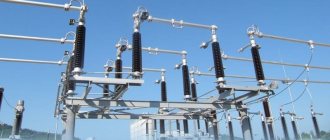
Figure 1 shows a section of a line with high-voltage disconnecting devices.
Figure 1. Line section with high-voltage disconnectors
The switching mechanisms under consideration have two important qualities that allow you to control the switching process:
This design of the disconnector allows maintenance personnel to quickly assess the condition of the working parts of the switching mechanism before switching on, as well as visually monitor the position of the contact knives in a specific situation. Disconnectors always operate using high voltage switches, both outdoors and indoors.
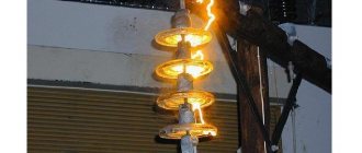
Such devices can be used to switch transformers operating at no-load, as well as to disconnect lines with circulating pickup currents. With appropriate shunting devices, it is possible to disconnect live electrical circuits or turn off low-power transformer load currents. In this case, an arc discharge is always observed at the initial stage of shutdown or before switching on, when the contacts approach the breakdown distance.
The arcing time is reduced by the presence of contact springs. An exception is the class of load switches, the design of which includes autogas arc extinguishing devices - VNA. Such switches can be used as high-voltage disconnectors, which are used for switching sections of circuits up to 10 kV. (Fig. 2).
Main Applications
High voltage circuit disconnectors are used in many applications. With their help they serve:
The ability of three-pole and single-pole disconnectors to switch charging currents of overhead wires and cable lines, turn on and off induction currents of power transformers, cut off equalizing currents, and disconnect circuits with small load currents makes these devices indispensable in various power systems.
The areas of application of high-voltage disconnectors are regulated by PTEEP. The rules allow their use in networks of 6 - 10 kV, to switch on or off load currents up to 15 A or equalizing currents up to 70 A.
Separators
What is a separator?
A separator is a high-voltage device designed to automatically disconnect damaged sections of a circuit during a dead-reclosure pause, since its design is not designed to extinguish an electric arc. The separator device is the same as the disconnector. The difference from the latter is that the separator in combination with the short-circuiter creates a separator-short-circuit system which represents an alternative to the high-voltage circuit breaker.
The separator is a disconnector that quickly turns off a de-energized circuit after a command is given to its drive. If in a conventional disconnector the shutdown speed is very low, then in a separator the shutdown process lasts 0.5-1.0 s. The separator disconnects damaged sections of the electrical circuit after the safety switch is turned off. The switch is triggered by an artificial short circuit created by a short circuit.
The separators are a two-column disconnector with grounding knives (ODZ); one ODZ-1A, ODZ-1B, two ODZ-2 or without them (OD), controlled by the SHPO drive (separator drive in the cabinet). Up to 110 kV inclusive, three poles of the separator are connected into a common three-pole device and controlled by one SHPO drive.
Separators for 220 kV are made in the form of three separate poles, each of which is controlled by an independent drive.
The separator is switched off automatically under the action of wound springs when a blocking relay or a shutdown electromagnet is activated, releasing the free release mechanism of the drive. The separator is switched on manually.
Operations performed by separators
The separators allow the following operations to be switched off and on:
- voltage transformers, charging current buses and substation equipment of all voltages (except capacitor banks);
- parallel branches under load current, if the disconnectors of these branches are bypassed by other switched-on disconnectors or switches;
- magnetizing currents of power transformers and charging currents of overhead and cable lines;
- neutrals of transformers and arc suppression coils in the absence of a phase-to-ground fault in the network.
Operating principle of separators
Typically, the separator is a chopping-type contact system without arc extinguishing and equipped with a spring-motor drive. In normal mode, the electric motor tensions the spring and places the mechanism on the latch. When a signal is given, the latch is released by a special electromagnetic release and, under the action of a tensioned spring, the separator opens the circuit. This principle (spring shutdown) is necessary for the energy independence of the separator operation (for its reliable operation). It is also necessary to note the mandatory blocking of switching off the separator under current.
Advantages of separators
Cheap - compared to a heavy high-voltage circuit breaker
Disadvantages of separators
Low reliability - since the separators are located mainly in outdoor switchgear, precipitation can lead to failure of the separator.
Design and principle of operation
The creation of a high-voltage disconnector was driven by the need for a switching mechanism capable of providing a safe and visually observable break in high-voltage energized circuits. The design of such a device is based on high reliability of contacts, ensuring the circuit is closed and opened in all weather conditions.
The design of the high-voltage disconnector does not provide for the presence of spark-extinguishing elements. Therefore, in order to prevent the formation of a high-power electric arc that can destroy contacts, the devices are connected in series with high-voltage load switches. Before disconnecting the desired line, use a switch to turn off the load.
The disconnector design consists of a rigid load-bearing frame on which the following elements are mounted:
Disconnectors intended for switching circuits whose voltage exceeds 110,000 V, consist of two contact movable half-blades, separated in opposite directions. The distance between the separated contacts is quite large, which eliminates the breakdown of this space in cases of unauthorized activation of the switch.
An example of a three-pole disconnector is shown in Figure 3.
Figure 3. Three-pole switch with vertical rotation of knives
Despite the fact that the radios operate with the load disconnected, the possibility of the presence of dangerous induced or capacitive currents cannot be excluded. In order to ensure complete safety for personnel, grounding blades are used, which are mounted on one platform and can perform their intended protective function only after the load switch is disconnected and the contacts connecting the serviced area to the live line are disconnected. Otherwise, a short circuit occurs between the grounded wires.
In order to eliminate short circuits caused by grounding blades as a result of accidental supply of rated currents, many models are equipped with locking mechanisms. The mechanisms block the movement of the knives when the grounding device is not removed or when the load is on. Most often, mechanical locking is used, but there are also electromagnetic and even hydraulic locking mechanisms. There are models with combined blocking elements.
Principle of operation
Connection or disconnection of the switched electrical circuit is ensured by turning the contact knives. Depending on the design, the moving contacts can be rotated vertically or horizontally. The drive that imparts force to the rotating mechanism is a rod with a handle, with the help of which the operator controls the contact knives. The drive handles are mounted directly on the supports under the disconnector.
Manual control is used mainly on overhead lines up to 6 kV. Knives on lines of 110 kV and above are controlled by electric drives using metal cabinets located at a safe distance.
Manual drive PR-3 lever type
Standard disconnectors are in most cases operated by manual lever drives, the operation of which depends entirely on the operator's muscular strength.
The kinematic diagram of the manual drive consists of three parts:
- The drive handle, which is a lever that rotates around an axis at one of the fixed ends by approximately 90 degrees. The lever can be equipped with a locking device for a padlock or electromechanical lock, as well as drive position sensors. The drive handle is usually installed on the front of the switchgear cabinet, for example, a KSO chamber. In fact, this part is usually called the drive.
- A rod, which at one end is attached to the drive lever, and at the other to a lever or coupling mounted on the axis of the disconnector. The rod is located entirely inside the switchgear cabinet; its length is always selected locally, based on the distance from the front side of the cabinet to the rear wall on which the disconnector is installed.
- Disconnector shaft driving the main or grounding contacts of the disconnector
Classification
The domestic industry produces high-voltage disconnectors of various types. They can be classified according to the following criteria:
In addition, devices differ in rated voltage and rated current for which they are designed. Products come with grounding switches (disconnectors RVZ, Fig. 4), with figured knives (RVF) and others.
Figure 4. RVFz 1063
The type of device can be determined by its designation.
The letters indicate:
For example, RV is an internal disconnector, and the abbreviation RLND means that this is a linear type of device with two support-insulating columns for outdoor use.