Hello, dear readers of the site. Intermediate electromagnetic relays are used in many electronic and electrical circuits and are intended for switching electrical circuits. They are used to amplify and transform electrical signals; remembering information and programming; distribution of electrical energy and control of the operation of individual elements, devices and equipment units; coupling of elements and devices of radio-electronic equipment operating at different voltage levels and operating principles; in alarm, automation, protection circuits, etc.
An intermediate electromagnetic relay is an electromechanical device that can switch electrical circuits and also control another electrical device. Electromagnetic relays are divided into permanent
and
alternating current
.
The operation of an electromagnetic relay is based on the interaction of the magnetic flux of the winding and a moving steel armature, which is magnetized by this flux. The figure shows the appearance of the RP-21 type intermediate relay.
Purpose of the intermediate relay
An intermediate relay is a device that ensures the operation of several electrical circuits.
This is an auxiliary device that is designed to control the operation of various machines and complexes. Ensures the operation of several electrical circuits at once when it is necessary to simultaneously switch different contacts.
For example, one of the contacts should display an alarm signal on the relay screen, and the other should turn off. Either one connection starts the machine, the other turns off another part of the device.
An intermediate relay (IR) is also used to slow down the reaction at the required high loads. For monitoring a main relay that switches large currents under high voltage conditions.
An intermediate relay is called because in the control circuit it is located between the pulse source it controls and the power executive circuits.
Safety precautions during operation
There is a list of some measures that must be carried out for the correct and safe operation of the device.
Let's look at the list of these nuances:
- Personnel who service the relay must carefully check the functionality of the device and the condition in which it is located.
- Contact connections must be periodically cleaned from contamination.
- You must immediately remove the device from the network if damage is detected.
- It is necessary to comply with operational requirements for temperature, operating conditions and others.
- If problems occur, you should contact a specialist.
RP device
Design of the intermediate relay
The design of the device depends on the manufacturer and can be changed in accordance with the purpose. The standard device consists of the following components:
- electromagnetic coil with core;
- magnetic circuit;
- spring mechanism;
- contact group.
The coil winding contains a large number of turns of insulated copper wire. Inside there is a metal core, which is secured by an L-shaped plate (yoke). A plate or armature is installed above the coil. It is made of metal and is held in place by a return spring. The moving contacts are fixed to the anchor. A pair of fixed contacts are located opposite. The core and coil together form an electromagnet. Parts such as the yoke, core, and armature are components of the magnetic circuit.
RP can be designed for both direct and alternating current, with voltage from 12 to 220 volts. Externally, the devices are no different. The device operating on direct current has a solid magnetic circuit. If it is assembled from separate plates, the device is designed to operate with alternating current not exceeding 10 amperes.
For ease of installation, the devices use unique blocks, which allows you to install a 220V intermediate relay on a DIN rail. The device has holes for relay contacts, as well as contact screws for connecting external conductors. Both input and output pins have the same numbering.
What technical characteristics to pay attention to
When choosing an intermediate relay, you need to know what parameters to pay attention to.
The choice of device should depend on:
- The type of electrical current used.
- The number and type of contact used in the device.
- Maximum values of long-term contact currents.
- Power consumption.
- Relay sizes.
- Voltage indicator.
- Operating conditions.
- Resistant to the effects of vibration, noise and others.
- The periods during which work with contacts occurs.
Do not neglect these parameters, because the correct functioning of the relay will depend on them.
Types of intermediate relays
Intermediate relay on Din-rail
Based on their design, they are divided into relays for electromagnetic intermediate or mechanical and electronic devices. Mechanical relays can operate under different conditions. These are durable and reliable devices, but not accurate enough. Therefore, more often their analogs are mounted in the circuit - electronic relays on a DIN rail. The relay can also be installed on a flat surface. To do this, the lock latches need to be moved apart.
Based on their purpose, devices are divided into the following categories.
- Combined interdependent devices operating in a group.
- Logic devices that operate on microprocessors in a circuit with digital relays.
- Measuring, with an adjustment mechanism, triggered at a certain signal level.
According to the method of operation of the RP, there are direct ones, which directly open or close the circuit, and indirect ones, which work together with other devices. They do not open the circuit immediately after a signal is received.
There are devices of the maximum switching type, when operation occurs at the moment the threshold value of the circuit parameter increases. The minimum type is triggered during a decrease in characteristics.
According to the method of connection to the circuit, there are primary ones that can be connected directly to the circuit. Secondary ones are installed through inductors or capacitors.
There is a group of protection relays that are similar in principle to intermediate relays. There are semiconductor devices, induction, polarization and electromagnetic. For example, a phase control device is a kv relay.
Principle of operation
Control circuit for an asynchronous motor using an intermediate relay.
The basis of operation is the coordinated interaction of the magnetic flux of the coil and the moving armature, which is magnetized by this flux. The armature is held by a spring and does not touch the core until voltage is applied to the winding.
When current begins to flow, the magnetic field magnetizes the core. It attracts the armature, forcing the spring tension. The moving contacts on the armature move, closing or opening with the fixed contacts. After turning off the voltage, the current disappears, the core is demagnetized, and the return spring returns the armature and contacts to their original position.
In relation to the purpose of the relay, the contacts can be normally open, normally closed and changeover. One device can have several groups of contacts at once. This design allows you to simultaneously control several electrical circuits.
There are special requirements for contacts. They must have good electrical conductivity, low contact resistance, no tendency to weld, and also have greater wear resistance and a long service life.
Contacts are made from an alloy of hard and refractory metals and metal-ceramic compounds. More often they are made of silver. The material has low resistance, high electrical conductivity, good technological properties, and is also relatively inexpensive.
In the diagrams, the relay coil is designated as a rectangle with the letter “K” and a serial number. Contacts are written with the same letter, but with two numbers. Of these, the first means the serial number of the relay, and the second means the number of the contact group to which it belongs. Numbers are written with a dot. The contacts are connected by a straight dashed line if they are located next to each other.
The contacts in the diagram are shown under the condition that no voltage is supplied to the relay. The diagram and designation of the contact output are usually indicated by the manufacturer on the cover that covers the working part of the device.
Pass-through and crossover switches
I have an article on this issue. It says that if you need to control the light from 2 places, pass-through switches (or switches, as people say) are used. To each of them you need to lay three wires.
The scheme will be like this:
Classic lighting switching scheme from two points with pass-through switches
If there are 3 or more light control points, you need to install cross switches (except for the two pass-throughs at the edges of the circuit), with 4 wires laid to each of them:
Circuit with a cross switch for turning on lighting from three places
If you need control from 4 places, but you need 2 pass-through and 2 cross switches, respectively:
Scheme of two pass-through and two cross switches for turning on the light from four places
And so on, the number of cross switches increases.
Disadvantages of circuits with pass-through and crossover switches
Some disadvantages of classic circuits with switches may seem unobvious or insignificant, but I will still list them.
- Pass-through and cross-over switches have a higher price tag than regular switches.
- They are often out of stock in stores.
- More wiring required.
Application area
An intermediate relay in the electrical panel
of the RP is present in almost all power, control and protection circuits. Switching devices are used in substations, control rooms, and boiler rooms. On a production line, the device can perform both simultaneously and sequentially several switchings in control or power circuits. RP is widely used in computing, telecommunications, controls and other electronic devices.
In water supply and heating systems, when the deep pump is turned on, power is supplied to the coil. When the contacts are closed, the control system begins to operate. The display displays voltage parameters, phase load currents, if necessary, temperature and other data depending on the complexity of the circuit.
In the heating system, the relay acts as an amplifier of the control signal. The thermal sensor sends a signal that turns on the RP. The contacts of the latter supply voltage to the winding, after which the contacts close. In this way, power is connected to the heating element, boiler, boiler and other powerful heating devices.
Connection diagrams
After the intermediate relay has been installed in the electrical cabinet, it should be connected to the electrical circuit. For this purpose, the contacts of the coil itself and direct contact elements are used. The relay usually has several pairs of NO normally open and NC normally closed contacts. The normal position is considered to be the absence of a signal to the coil. Since the coil does not have polarity, the contacts are connected arbitrarily.
Such a device is installed in control and automation circuits. Located between the actuator (for example, a contactor) and the reference source. The figure shows the electrical diagram of the device:
The picture shows an intermediate relay without voltage supply. If you apply it, the contacts will switch. The voltage in the coil can be different: 220, 24 and 12 volts.
How to connect the device is shown in the figure below:
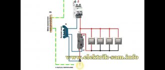
In some cases, an intermediate type relay is used as a contactor, then the installation diagram will look like this:
As you can see, the intermediate relay has three groups of contacts that control the load and one group to hold the current in the coil. You can install an additional contactor, then the device is connected first to the contactor.
This device can also be connected to a motion sensor. Thanks to it, it is possible to connect several powerful lamps to the motion sensor system. Installation occurs as follows: the winding of the device is connected to the sensor, and the power contact switches the load in the lighting system. How to install such a sensor is shown below:
Another option for installing an electronic starter is to a thermostat. The diagram is shown in the picture (click to enlarge):
In this case, the thermostat and starter are connected in sequential order to the first phase and neutral wire (in the diagram they are designated as T1 and K1, respectively). The installation of the remaining contacts of the starter is carried out evenly between other phases.
Finally, we recommend watching a useful video on the topic:
https://youtube.com/watch?v=d6BA3PFlwCU
That's all I wanted to tell you about how to properly connect this device. We hope that the video instructions and intermediate relay connection diagrams provided were useful to you!
Product parameters
RPs of different types have their own set of parameters regarding technical characteristics. The need for certain data arises based on the tasks assigned to the device. The main characteristics responsible for the normal operation of the relay:
- sensitivity;
- current (voltage) of actuation, release, hold;
- safety factor;
- operating current;
- winding resistance;
- switching capacity;
- dimensions;
- electrical insulation.
It is necessary to know at what temperature and humidity the device can be operated, the explosiveness of the working environment, and the permissible dust concentration. These parameters are set out in the technical specifications or instructions for use. The type of current and operating voltage is indicated on the winding of the device.
RP is an important and integral component of most circuits in the energy sector. The variety of models indicates that such a switching device is capable of fully performing many functions in any circuit.