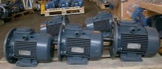
Asynchronous motors AIR - have general industrial use and provide drive in machines and mechanisms through the conversion of electrical energy into mechanical energy. They have characteristics typical for this type of equipment that meet the requirements of GOST.
All options under consideration are asynchronous, three-phase, with a squirrel-cage rotor and the BEZ trademark. We hope that we will be able to provide you with information that will help you decide on the required model and you will be able to buy an AIR engine already being confident in your choice.
Mounting version IMxxxx
The mounting design of the AIR electric motor is designated by the Latin letters IM and four numbers after them. Also sometimes found is a designation according to the international standard IEC60034-7 (code I), including the Latin letters IM, the Latin letter B or V and 1 to 2 digits.
The first number is the design of the electric motor
1- electric motor on feet with bearing shields
2- electric motor on feet with bearing shields and a flange on one shield
3- electric motor without feet with bearing shields and a flange on one shield
The second and third numbers indicate the spatial method of mounting the electric motor. If the third digit is “8”, for example IM1081, then such an electric motor can be mounted in any position.
The fourth digit is the design of the shaft end
1- electric motor with one cylindrical shaft end
2- electric motor with two cylindrical shaft ends
3- electric motor with one conical shaft end
4- electric motor with two conical shaft ends
General information about AIR engines
Asynchronous electric motors of the AI series were created by specialists from countries that are part of the international organization Interelectro. This series is considered the basic one, on the basis of which units in modified and specialized versions were developed. The power of such motors covers a wide range, ranging from 25 W to 400 kW. The height of the rotation axis also ranges from 45-355 mm.
The power and height of the rotation axes in AI units are made in two versions - P and S. This is where the abbreviation AIR arose along with another abbreviation AIS. The first option was used back in the Soviet Union, and the second was adopted by the European Electrotechnical Committee for Standardization. All foreign companies are guided by these standards, which is why AIR engines are used in the domestic Russian market, and AIS engines are exported. Each asynchronous electric motor AIR is one step higher in power than the AIS at the same height of the rotation axis.
- Basic. Includes symbols that determine the series, power and engine speed. For example, the marking AIR200M6 corresponds to the AI series with alignment according to option P, the axis of rotation is located at a height of 200 mm, M is the dimensions (length) of the housing according to the installation dimensions, 6 is the number of poles.
- Basics. In this case, the basic designation additionally includes the electrical and structural modification, the type of protection and cooling used. In addition, specialized design is taken into account, including in accordance with environmental conditions. Consequently, the marking AIRBS100M4NPT2 will be deciphered as follows: AIR100M4 - basic designation, B - closed type design, natural cooling without blowing, C - increased slip, N - low noise level, P - installation dimensions of increased accuracy, T - use in tropical climates, 2 – accommodation category.
- Complete. In addition to the main designation, it contains additional design and electrical characteristics. In this case, the voltage value is added to the main designation: 220/380V, network frequency - 60, design according to the installation method and shaft end - IM2181, output device and number of fittings - K3-N-3, type of flange panel - F-100.
Specifications
The installation and subsequent operation of the AIR electric motor must be adjusted to the mechanical load connected to its shaft, connection and operating conditions. The technical characteristics of the electric machine are selected in accordance with the above parameters. The engine characteristics are also indicated in the passport or on the nameplate.
Key technical data include:
- Power – determines the amount of electricity processed; for AIR electric motors this parameter ranges from 0.12 to 315 kW.
- The supply voltage depends to a certain extent on the winding connection diagram. AIR electric motors can be connected either in star or triangle, so the voltage is indicated for both methods - 220/380 or 380/660V.
- Rotation speed is the number of revolutions per unit of time; for the AIR brand it can range from 750 rpm to 3000 rpm.
- Efficiency - determines the ratio between energy expended and work done.
- The permissible temperature range is usually from – 40 to + 45ºС.
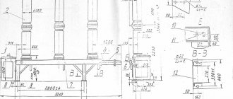
- Type of installation - in total there are three methods for the AIR electric motor: IM1081 - on the frame (horizontally), IM2081 both on the frame and on the flange (both horizontally and vertically), IM3081 only on the flange (vertically). An example of basic design options is shown in the figure below:
Rice. 3. Method of mounting the AIR electric motor
- Electrical and magnetic losses are determined by the open circuit voltage and short-circuit current.
- Geometric dimensions - indicate the main dimensions and distances from the elements of the electric machine to the nearest parts with which the motors are used.
- The degree of dust and moisture protection is indicated by two Latin letters IP and a pair of numbers, one of which determines resistance to dust, and the second to moisture.
The general industrial purpose of some of them involves technical features, which are indicated by the corresponding letters with which the engines are produced:
- B – ensures operation in high temperature conditions;
- B – built-in electrical machines;
- C – with increased sliding parameter;
- E – with the function of forced rotor braking.
- E2 – with manual braking control.
- ZE is a three-phase device for connecting to a single-phase network.
- F – for pumping units.
- RZ - in motor-gear devices.
- Sh – general industrial electric motors for the clothing industry.
- P – with high precision mounting characteristics.
- F – oil-resistant version.
- A – used in nuclear power plants.
- X2 – increased chemical resistance.
General scheme for marking electric motors
1. Series designation:
AIR, A, 4A, 5A, AD, 7AVER - general industrial electric motors with power adjustment according to GOST 51689-2000
AIS, 6A, IMM, RA, AIS - general industrial electric motors with power binding according to the European standard DIN (CENELEC)
AIM, AIML, VA, AV, VAO2, 1VAO, 3V - explosion-proof electric motors
AIU, VRP, AVR, 3AVR, VR - explosion-proof mining electric motors
A4, DAZO4, AOM, DAV, AO4 - high-voltage electric motors
2. Sign of modification:
M - modernized electric motor (for example: ADM63A2U3)
K-electric motor with a wound rotor (for example: 5 ANK280A6)
X-electric motor with aluminum frame (for example: 5AMX180M2U3)
E- single-phase electric motor 220V (for example: AIRE80S2U3)
N - protected electric motor with self-ventilation (for example: 5AN200M2U3)
F - protected electric motor with forced cooling
C- electric motor with increased slip (for example: AIRS180M4U3)
B- built-in electric motor (for example: ADMV63V2U3)
P - electric motor with increased starting torque (for example: AIRR180S4U3)
P-electric motor for driving a fan in poultry farms (“poultry house”)
3. Dimensions (height of the shaft rotation axis above the mounting surface) mm:
50, 56, 63, 71, 80, 90, 100, 112, 132, 160, 180, 200, 225, 250, 280, 315, 355, 400
4. Installation dimensions or core length:
A, B - core length option
S, M, L - variant of core length and installation dimensions along the length of the bed
X, XK, Y, YK - stator core length option for high-voltage motors
5. Number of poles:
2 (3000 rpm), 4 (1500 rpm), 6 (1000 rpm), 8 (750 rpm), 10 (600 rpm), 12 (500 rpm)
4/2, 6/4, 8/6, 12/4, 12/6, 6/4/2, 8/6/4, etc. — multi-speed electric motors
6. Sign of design modification:
B - electric motor with built-in winding temperature protection sensor
B1 - electric motor with temperature protection sensor for windings and bearing units
B2 - electric motor with winding temperature protection sensor and heater
E - electric motor with built-in electromagnetic brake (for example: AIR80A2EU3)
E2 - electric motor with built-in brake and release handle
P - electric motor with increased accuracy of installation dimensions
Ж - electric motor for driving monoblock pumps (for example: AIR80A2ZHU2)
N - low noise electric motor (for example: 5AN180S4/16NLBUHL4)
L - electric motor for driving elevators (for example: 5AN180S4/16NLBUHL4)
C - electric motor for driving oil pumping units (for example: AIR180S4SNU1)
Tr - electric motor for axial fans in transformer cooling systems
P3 - electric motor for gearmotors
7. Climatic version (GOST 15150-69)
U - for a macroclimatic region with a temperate climate
UHL - for macroclimatic regions with temperate and cold climates
HL - for a macroclimatic region with a cold climate
T - for macroclimatic regions with both dry and humid tropical climates
M - for the macroclimatic region of the region with a moderately cold maritime climate
О - for all macroclimatic regions on land, except for very cold ones (general climatic version)
B - for all macroclimatic regions on land and sea, except very cold (all-climatic version)
8. Placement categories (GOST 15150-69)
1- for outdoor use
2- for use under a canopy, in tents, body trailers
3- for use in rooms without controlled climatic conditions
4- for use in rooms with artificially controlled climatic conditions
5- for use in rooms with high humidity
0.55 kW
| 1000 rpm | DIN | GOST | GOST |
| Motor type | АIS80В6 | AIR71V6 | AIR80A6 |
| Power P, kW | 0.55 kW | 0.55 kW | 0.75 kW |
| Synchronous frequency, rpm | 1000 | 1000 | 1000 |
| Dimensions, h | 80 | 71 | 80 |
| Shaft diameter d1, mm | 19 | 19 | 22 |
| Mounting paws width b10, mm | 125 | 112 | 125 |
| Fastening of paws along length L10, mm | 100 | 90 | 100 |
| Flange mounting at d20 centers, mm | 165 | 165 | 165 |
| “Flange lock” d25, mm | 130 | 130 | 130 |
| 1500 rpm | DIN | GOST | GOST |
| Motor type | АIS80А4 | AIR71A4 | AIR80A4 |
| Power P, kW | 0.55 kW | 0.55 kW | 1.1 kW |
| Synchronous frequency, rpm | 1500 | 1500 | 1500 |
| Dimensions, h | 80 | 71 | 80 |
| Shaft diameter d1, mm | 19 | 19 | 22 |
| Mounting paws width b10, mm | 125 | 112 | 125 |
| Fastening of paws along length L10, mm | 100 | 90 | 100 |
| Flange mounting at d20 centers, mm | 165 | 165 | 165 |
| “Flange lock” d25, mm | 130 | 130 | 130 |
| 3000 rpm | DIN | GOST | GOST |
| Motor type | AIS71B2 | AIR63V2 | AIR71A2 |
| Power P, kW | 0.55 kW | 0.55 kW | 0.75 kW |
| Synchronous frequency, rpm | 3000 | 3000 | 3000 |
| Dimensions, h | 71 | 63 | 71 |
| Shaft diameter d1, mm | 14 | 14 | 19 |
| Mounting paws width b10, mm | 112 | 100 | 112 |
| Fastening of paws along length L10, mm | 90 | 80 | 90 |
| Flange mounting at d20 centers, mm | 130 | 130 | 165 |
| “Flange lock” d25, mm | 110 | 110 | 130 |
Electric motor connection diagram
Nominal data are given in accordance with GOST 28173-89.
AIR electric motors designed for a voltage of 220/380V must be connected when the windings are connected in a star to a linear voltage of 380V, and when the windings are connected in a delta to a linear voltage of 220V.
Similarly, AIR electric motors designed for a voltage of 380/660V must be connected when the windings are connected in a “star” to a linear voltage of 660V, and when the windings are connected in a “delta” to a linear voltage of 380V.
For electric motors designed for a voltage of 380V, the windings are by default connected in a “star” for a linear voltage of 380V.
A different connection of the windings will lead to failure of the electric motor and the manufacturer’s refusal of warranty obligations due to the presence of “consumer fault”.
Nuances of operation
In the case of installation and subsequent use of basic AIR electric motors, it is important to observe and take into account some of the nuances specified by the manufacturer, namely:
The electric motor must be connected through a protection system against short circuit currents, overheating, phase failure, overloads, etc. When performing installation work or connecting the AIR electric motor, it is important to ensure an air flow for cooling; the casing itself must be moved away from obstacles by at least 20mm. In case of couplings, the shaft of the AIR electric motor is aligned coaxially with the load. Regardless of the connection method, subsequent balancing of the load on the shaft is required. It is important to consider that the rotor is balanced without keys.
INDUCTION ELECTRIC MOTORS SIEMENS
OOO "PROMOBORUDOVANIE"SIEMENSSIEMENSDIN EN ISO 9001
Distinctive features of electric motors:
- increased efficiency;
- compliance with European (DIN/VDE) and international standards (IEC/EN);
- production is certified according to DIN EN ISO 9001 standard;
- high-quality steel (iron, copper and aluminum);
- improved cooling system and bearing units;
- ease of operation and maintenance;
- lower temperature loads;
- long service life of windings and bearings due to lower temperature loads;
- reduced noise during operation;
- increased overload capacity due to improved cooling;
- suitable for use with frequency converters, resistant insulation DURIGNITIR2000;
- various design options.
Explanation of designations for SIEMEMS electric motors
| Position | Decoding | Example | |||||||||||||||||||||||||||||||
| 1.2.3. 4. | Motor type | 1LA7 is a three-phase asynchronous electric motor with a squirrel-cage rotor. | |||||||||||||||||||||||||||||||
| 5.6. | Dimensions | ||||||||||||||||||||||||||||||||
| 7. | Dimensions |
|
Installation of meters and electrical wiring to them
1.5.27. Meters must be located in dry rooms that are easily accessible for maintenance, in a place that is sufficiently free and not cramped for work, with a temperature in winter not lower than 0°C.
General industrial meters are not allowed to be installed in rooms where, due to production conditions, the temperature can often exceed +40°C, as well as in rooms with aggressive environments.
It is allowed to place meters in unheated rooms and corridors of switchgears of power plants and substations, as well as in outdoor cabinets. In this case, provision should be made for their stationary insulation for the winter through insulating cabinets, hoods with heated air inside them with an electric lamp or heating element to ensure a positive temperature inside the hood, but not higher than +20°C.
1.5.28. Meters designed to account for electricity generated by power plant generators should be installed in rooms with an average ambient temperature of +15+25°C. In the absence of such premises, it is recommended that meters be placed in special cabinets, where the specified temperature must be maintained throughout the year.
1.5.29. Meters must be installed in cabinets, chambers of complete switchgears (KRU, KRUP), on panels, switchboards, in niches, on walls with a rigid structure.
It is allowed to mount meters on wooden, plastic or metal panels.
The height from the floor to the meter terminal box should be within 0.8-1.7 m. A height of less than 0.8 m is allowed, but not less than 0.4 m.
1.5.30. In places where there is a danger of mechanical damage to meters or their contamination, or in places accessible to unauthorized persons (passages, staircases, etc.), a locked cabinet with a window at dial level should be provided for meters. Similar cabinets should also be installed to co-locate meters and current transformers when performing metering on the low voltage side (at the consumer input).
1.5.31. The designs and dimensions of cabinets, niches, panels, etc. should provide convenient access to the terminals of meters and current transformers. In addition, it must be possible to conveniently replace the meter and install it with a slope of no more than 1°. The design of its fastening must ensure the possibility of installing and removing the meter from the front side.
1.5.32. Electrical wiring to meters must meet the requirements given in Chapter. 2.1 and 3.4.
1.5.33. The presence of rations in the electrical wiring to the settlement meters is not allowed.
1.5.34. The cross-sections of wires and cables connected to meters must be taken in accordance with 3.4.4 (see also 1.5.19).
1.5.35. When installing electrical wiring to connect direct-connection meters, it is necessary to leave the ends of the wires with a length of at least 120 mm near the meters. The insulation or sheath of the neutral wire at a length of 100 mm in front of the meter must have a distinctive color.
1.5.36. For safe installation and replacement of meters in networks with voltages up to 380 V, it must be possible to turn off the meter by switching devices or fuses installed before it at a distance of no more than 10 m. Voltage relief must be provided from all phases connected to the meter.
Current transformers used to connect meters for voltages up to 380 V must be installed after switching devices in the direction of power flow.
1.5.37. Grounding (grounding) of meters and current transformers must be carried out in accordance with the requirements of Chapter. 1.7. In this case, the grounding and neutral protective conductors from meters and current transformers with voltages up to 1 kV to the nearest terminal assembly must be copper.
1.5.38. If there are several connections at the facility with separate electricity metering, the meter panels must contain inscriptions with the names of the connections.
Protection degree IPxx (GOST 17494-87)
The first digit is protection against penetration of solid bodies.
- unprotected electric motor
1- electric motor, protected from solid bodies with a diameter of more than 50 mm
2- electric motor, protected from solid bodies with a diameter of more than 12 mm
3- electric motor, protected from solid bodies with a diameter of more than 2.5 mm
4- electric motor, protected from solid bodies with a diameter of more than 1.0 mm
5- electric motor, protected from dust
The second number is protection against water penetration
- unprotected electric motor
1- electric motor protected from vertically dripping water
2- electric motor, protected from falling drops at an angle of up to 15º to the vertical
3- electric motor, protected from falling drops at an angle of up to 60º to the vertical (from rain)
4- electric motor, protected from water sprayed from all directions
5- electric motor, protected from water jets from all directions.
Possible built-in options for SIEMENS electric motors
| Option | Description |
| A 11 | RTS motor protection - thermistors with 3 temperature sensors for emergency shutdown |
| A 12 | RTS motor protection - thermistors with 6 temperature sensors for emergency shutdown and alarm |
| A 23 | Motor temperature sensor with built-in thermistor KTY 84-130 |
| A 25 | Motor temperature sensor with built-in 2 thermistors KTY 84-130 |
| M 72 | Version for Zone 2 direct connection to the network (Ex nA II T3) |
| M 73 | Version for Zone 2 powered by frequency drive (Ex nA II T3) |
| M 34 | Version for Zone 21 (IP65) direct connection to the network |
| M 38 | Version for Zone 21 (IP65) powered by frequency drive |
| M 35 | Version for Zone 22 (IP55) direct connection to the network |
| M 39 | Version for Zone 22 (IP55) powered by frequency drive |
| N 57 | Encoder (HTL) |
| N 58 | Encoder (TTL) |
| G 17 | Forced cooling |
| H 61 | Forced cooling and encoder (HTL) |
| H 97 | Forced cooling and encoder (TTL) |
| G 26 | Brake and encoder |
| H 62 | Brake and encoder (HTL) |
| H 98 | Brake and encoder (TTL) |
| H 63 | Brake and forced cooling |
| H 64 | Brake, and forced cooling and encoder (HTL) |
| H 99 | Brake and forced cooling and encoder (TTL) |
| K 82 | Manual brake |
| C 00 | Brake supply 24 V DC |
| C 01 | Brake power 400V, 50Hz |
| C 02 | Brake power 180 VDC (from MM411-ECOFAST) |
| G 50 | Mounting location for vibration sensor for bearing monitoring |
| K 50 | Version IP 65 |
| K52 | Version IP 55 |
| K 16 | Second shaft end (Standard) |
| K 20 | Bearings for increased shaft loads |
| K 37 | Low noise version for 2-pole motors, direction of rotation clockwise |
| K38 | Low noise version for 2-pole motors, direction of rotation counterclockwise |
| K 45 | Anti-condensation heating 230 V |
| K 46 | Anti-condensation heating 115 V |
| K9, 10 | Terminal box on the side |