In order for electric current to flow for a long time, several conditions must be met. One of them is the closed circuit. Its components ensure the creation of a circuit that allows charge carriers to flow. The minimum number of elements required for this is three. But the real chain can be as large as desired, although some parts must be in it.
What are electrical circuits
An electrical circuit is a set of devices necessary for the passage of electric current through them.
An electrical circuit is a complex of various elements connected to each other. It is designed to allow electrical current to flow where transients occur. The movement of electrons is driven by potential differences and can be described using terms such as voltage and current.
The internal circuit is provided by connecting voltage as a power source. The remaining elements form the external network. For the movement of charges in the field power source, the application of an external force will be required. This can be a winding of a generator, transformer or galvanic source.
For such a system to function correctly, its circuit must be closed, otherwise no current will flow. This is a prerequisite for coordinated operation of all devices. Not every circuit can be an electrical circuit. For example, grounding or protection lines are not grounding or protection lines because no current flows through them in normal operation. They can be called electric based on their operating principle. In an emergency, current passes through them, and the circuit closes, going into the ground.
Depending on the power source, the voltage in the circuit can be constant or variable. The battery of elements provides constant voltage, and the windings of generators or transformers provide alternating voltage.
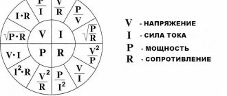
Formulas
Similar to potential energy in a gravitational field, there is a formula for the electrical energy of a charge with charge magnitude q that is located at a location with electrical potential U: , el = q * U. The given formula reflects the electric potential energy of the charge q.
But what happens when electric current flows? Then you replace the electric charge q in the formula for Epot with I * t, i.e. current strength I multiplied by time t. That is, you will get the formula: Epot, el = I * t * U.
A capacitor can also store electrical energy. The formula for calculating the accumulated energy is as follows: Ec = 0.5 * C * U2, where C is the capacitance of the capacitor.
Main components
Electric Current Inverter
All components in a circuit participate in the same electromagnetic process. They are conventionally divided into three groups.
- Primary sources of electrical energy and signals can convert energy of a non-electromagnetic nature into electrical energy. For example, a galvanic cell, a battery, an electromechanical generator.
- The secondary type has electrical energy at both the input and output. Only its parameters change - voltage and current, their shape, magnitude and frequency. Examples could be rectifiers, inverters, transformers.
- Active energy consumers convert electric current into lighting or heat. These are electrothermal devices, lamps, resistors, electric motors.
- Accessory components include switching devices, measuring instruments, connecting elements and wire.
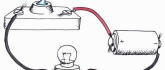
The basis of an electrical network is a circuit.
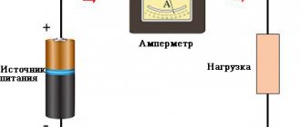
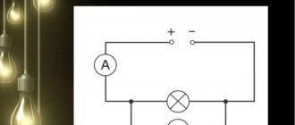
This is a graphic drawing that contains conventional images and symbols of elements and their connection. They are carried out in accordance with GOST 2.721-74 - 2.758-81 The circuit of the simplest line includes a galvanic element. An incandescent lamp is connected to it via a switch using wires. It includes a voltmeter and an ammeter to measure current and voltage.
Open and closed circuits
In "open" and "closed" circuit terminology, a switch in which a contact from one connection terminal is connected to a contact from another terminal (for example, a switch with a blade fully touching a fixed contact) allows current to flow through itself continuously and is called a closed switch. . Conversely, a switch that breaks the continuity of the circuit (for example, a switch with a blade that does not touch the fixed contact) does not allow current to pass and is called an open switch.
Circuit classification
Electrical circuits are classified by type of complexity: simple (unbranched) and complex (branched). There is a division into DC and AC circuits, as well as sinusoidal and non-sinusoidal. Based on the nature of the elements, they are linear and nonlinear. AC lines can be single-phase or three-phase.
Branched and unbranched
The same current flows in all elements of an unbranched circuit. The simplest branched line includes three branches and two nodes. Each branch has its own current flowing. A branch is defined as a section of a chain that is formed by sequentially connected elements located between two nodes. A node is a point where three branches meet.
If a dot is placed on the diagram at the intersection of two straight lines, there is an electrical connection of two lines at this place. If the node is not marked, the chain is unbranched.
Linear and nonlinear
An electrical circuit in which consumers do not depend on the voltage and direction of currents, and all components are linear, is called linear. The elements of such a circuit include dependent and independent sources of currents and voltages. In a linear element, the resistance of the element does not depend on the current, for example, an electric furnace.
In nonlinear, passive elements depend on the values of the direction of currents and voltage, and have at least one nonlinear element. For example, the resistance of an incandescent lamp depends on voltage and current surges.
Exercises
Exercise No. 1
Draw a diagram of a circuit containing one galvanic element and two bells, each of which can be switched separately.
What will be responsible in the circuit for turning on the bell? Key . And since we have two bells and each needs to be turned on independently of the other, there must be two keys (Figure 4).
Figure 4. Electrical circuit diagram with two bells, each of which can be turned on separately
Pay attention to the location of the bells. If we simply connect them one after the other, it will be the wrong solution. After all, if we then turn off one bell, it will be a kind of “broken wire” for the second, and the second bell will not work.
Exercise No. 2
Come up with a diagram for connecting a galvanic cell, a bell and two buttons arranged so that you can call from two different places.
To make calls from two different places we can place buttons as shown in Figure 5.
Figure 5. Electrical circuit diagram with a bell and two buttons
The second key (button) can be placed on the other side of the chain in a similar way.
Exercise #3
Figure 6 shows a diagram of the connection of a lamp and two switches.
Look at the diagram and think about where such wiring can be used. Figure 6. Circuit diagram with a lamp and two switches
Please note that keys/switches connected to each other are depicted in this way. Those. When one is closed, the other is also closed, and vice versa.
This type of wiring is convenient to use in large rooms. For example, when entering a long corridor, you turn on the light next to the door. You go to the other end of the corridor to another room, and you need to turn off the light behind you. There is a second button next to you. Clicking on it turns off the light.
You can also use this version of the electrical circuit if different people from different places in the room need to turn the light on/off.
Designations of elements on the diagram
Before proceeding with the installation of equipment, it is necessary to study the regulatory accompanying documents.
The diagram allows you to convey to the user the full characteristics of the product using letter and graphic symbols entered into a unified register of design documentation. Additional documents are attached to the drawing. Their list can be indicated in alphabetical order with digital sorting on the drawing itself, or on a separate sheet. Ten types of circuits are classified; in electrical engineering, three main circuits are usually used.
- Functional has minimal detail. The main functions of the nodes are represented by a rectangle with letter symbols.
- The schematic diagram shows in detail the design of the elements used, as well as their connections and contacts. The required parameters can be displayed directly on the diagram or in a separate document. If only part of the installation is indicated, it is a single-line diagram; when all elements are indicated, it is complete.
- The electrical wiring diagram uses positional designations of elements, their location, installation method and sequence.
To read electrical diagrams, you need to know the graphic symbols. The wires that connect the elements are represented by lines. The solid line is a general designation for wiring. Above it may be information about the installation method, material, voltage, current. For a single-line diagram, a group of conductors is depicted with a dotted line. At the beginning and at the end indicate the marking of the wire and the place of its connection.
Vertical notches on the wiring line indicate the number of conductors. If there are more than three, digital designation is performed. The broken line indicates control circuits, security, evacuation, and emergency lighting networks.
The switch in the diagram looks like a circle with a line tilted to the right. The device parameters are determined by the type and number of dashes.
In addition to the main drawings, there are substitution diagrams.
Unit of measurement of electrical energy
Since electrical energy is a form of energy, it has a unit of measurement called joule, abbreviated [J]. Designated as Epot, el . Electrical energy is also measured in watt-seconds [W * sec]. That is, 1 J = 1 W * sec.
To give you an idea of how much 1 J of electrical energy is, here's a quick example: In order for a 1 W LED bulb to burn for one second, you need 1 J of electrical energy.
Let's take a quick look at the units of measurement for this example. Watt is a unit of measurement of power. Power P is defined as work per unit of time, i.e. P = W/t .
Thus, power also has a unit of joule per second: [P] = J/s.
Thus, multiplying power by time gives the unit of energy: [P] * [t] =c * J/s = J.
A multiple of 1 W is 1 kilowatt-hour: 1 kW * h = 3.6 * 106 W * s = 3.6 * 106 J.
The unit of measurement "Watt" is named after the Scottish inventor JAMES WATT (1776-1819), the unit "Joule" is named after the English physicist James Prescott Joule (1818-1889).
Three-phase electrical circuits
Three-phase circuit in operating mode
Both single-phase and multi-phase systems are common among electrical circuits. Each part of a polyphase circuit is characterized by the same current value and is called a phase. Electrical engineering distinguishes two concepts of this term. The first is a direct component of a three-phase system. The second is a quantity that changes sinusoidally.
A three-phase circuit is one of the multiphase alternating current systems where sinusoidal EMF (electromotive force) of the same frequency acts, which are shifted in time relative to each other by a certain phase angle. It is formed by the windings of a three-phase generator, three power receivers and connecting wires.
Such circuits serve to ensure the generation of electrical energy, for its transmission, distribution, and have the following advantages:
- cost-effectiveness of electricity generation and transportation compared to a single-phase system;
- simple generation of a magnetic field, which is necessary for the operation of a three-phase asynchronous electric motor;
- the same generator set produces two operating voltages - linear and phase.
The three-phase system is beneficial when transmitting electricity over long distances. In addition, material consumption is significantly lower than single-phase ones. The main consumers are transformers, asynchronous electric motors, converters, induction furnaces, powerful heating and power units. Among single-phase low-power devices we can mention power tools, incandescent lamps, household appliances, and power supplies.
The three-phase circuit is characterized by a significant balance of the system. The methods for connecting the phases received the “star” and “triangle” structures. Typically, the phases of generating electric machines are connected by a “star”, and the phases of consumers are connected by a “star” and a “triangle”.
The total resistance of the circuit when the active and reactive elements are connected in parallel.
In order to calculate the total resistance of a circuit composed of active and inductive resistances connected to each other in parallel (Fig. 5, a), you must first calculate the conductivity of each of the parallel branches, then determine the total conductivity of the entire circuit between points A and B and then calculate the total resistance of the circuit between these points.
Figure 5. Circuit impedance when connecting active and reactive elements in parallel . a) - parallel connection of R and L; b) - parallel connection of R and C.
The conductivity of the active branch, as is known, is equal to 1/R, similarly, the conductivity of the inductive branch is equal to 1/ωL, and the total conductance is equal to 1/Z
Total conductivity is equal to the square root of the sum of the squares of active and reactive conductivity, i.e.
(7)
Reducing the radical expression to a common denominator, we get:
(8)
where:
(9)
Formula (9) is used to calculate the total resistance of the circuit shown in Fig. 5a.
Finding the total resistance for this case can also be done geometrically. To do this, you need to construct a resistance triangle on the appropriate scale, and then divide the product of the lengths of the legs by the length of the hypotenuse. The result obtained will correspond to the total resistance.
Similar to the case discussed above, the total resistance with a parallel connection of R and C (Fig. 5b) will be equal to:
(10)
The total resistance can also be found in this case by constructing a resistance triangle.
In radio engineering, the most common case is the parallel connection of inductance and capacitance, for example, an oscillatory circuit for tuning receivers and transmitters. Since the inductor always has, in addition to inductive resistance, also active resistance, the equivalent (equivalent) circuit of the oscillatory circuit will contain active resistance in the inductive branch (Fig. 7).
Figure 6. Equivalent circuit of an oscillatory circuit .
The impedance formula for this case will be:
(11)
Since usually the active resistance of the coil (R) is very small compared to its inductive resistance (ωL), we have the right to rewrite formula (11) in the following form:
(12)
In an oscillating circuit, the values of L and C are usually selected so that the inductive reactance is equal to the capacitive reactance, i.e., so that the condition is met
(13)
If this condition is met, the total resistance of the oscillatory circuit will be equal to:
(14)
where L is the inductance of the coil in H;
C is the capacitance of the capacitor in F;
R is the active resistance of the coil in Ohms.
DID YOU LIKE THE ARTICLE? SHARE WITH YOUR FRIENDS ON SOCIAL NETWORKS!
Related materials:
- Coil inductive reactance
- Inductor in an AC circuit
- Capacitor in an alternating current circuit. Capacitance of a capacitor.
- AC circuit resistance
- Resonance phenomenon
- Ohm's law for alternating current
- Voltage resonance in a series oscillating circuit
- Resonance of currents in a parallel oscillatory circuit
- Pulsating current
- Non-sinusoidal current
Comments
antip 08/07/2017 21:37 excellent article! I remember when I was studying at a technical school, the teacher explained all this to us just as simply. But the notes with the formulas got lost somewhere. Find out in more detail all the notations in the formulas, for example, what is w? The number of turns of the coil seems to be?
Quote
My beloved name 11/22/2016 07:13 Good article *if only it was three-phase current
Quote
Sergey9998 04/09/2016 10:45 And if there is no active resistance, but only inductive and capacitive, how to count?
Quote
Administrator 01/19/2015 16:24 Victor, everything is really simple. Formula 11 is the formula for parallel connection of two resistances, you can see it here. One resistance is the capacitive reactance of the capacitor, the second is the total resistance of the series section consisting of active resistance and inductive resistance (formula 2). More simple math
Quote
Victor___ 01/19/2015 14:29 It’s strange, what is there to praise here? Formula 11 is given from the ceiling. What if the scheme is slightly different? Without understanding how 11 was obtained, nothing can be done. What if there is a parallel section in a series connection? - Actually, at least shoot yourself.
Quote
Administrator 01/13/2015 02:49 Marat, thanks for the note and feedback, everything is fixed!
Quote
Marat 01/12/2015 20:34 Caption for Figure 5 a) Parallel connection of R and L And in general, the material is presented amazingly simply! Thanks to the author. In one evening I repeated and mastered all the basic material that was taught for an entire SEMESTER in the General Electrical Engineering discipline at the university. Now I’m reading it and I’m amazed at how simple and clear everything turns out to be!
Quote
Topic 09.11.2014 10:59 everything is clear and clearly described.
Quote
Natalya 10/15/2014 05:27 :lol: Thank you, everything is clear and precise.
Quote
Update list of comments
Laws applicable in electrical circuits
In the diagrams, the direction of currents is indicated by arrows. To calculate, you need to take the directions for voltages, currents, and EMF. When making calculations in electrical engineering, the following basic laws are used:
- Ohm's law for a straight section of a circuit, which determines the relationship between the electromotive force, the source voltage with the current flowing in the conductor and the resistance of the conductor itself.
- To find all currents and voltages, use Kirchhoff's rules, which operate between currents and voltages in any part of an electrical circuit.
- The Joule–Lenz law provides a quantitative estimate of the thermal effect of electric current.
In DC circuits, the direction of action of the electromotive force is indicated from negative to positive potential. The direction is taken to be the movement of positive charges. In this case, the arrow is directed from higher potential to smaller. Voltage is always directed in the same direction as the current.
In sinusoidal circuits, EMF, voltage and current are indicated using the half-cycle of the current, while it does not change its direction. To emphasize the difference in potentials, they are denoted by the signs “+” and “–”.
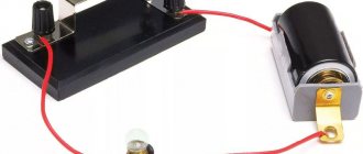
Blade switch
Perhaps the best type of switch to illustrate the principle of operation is the blade type switch:
Figure 4 – Knife type switch
A knife switch is nothing more than a conductive arm that is free to pivot on a hinge, making physical contact with one or more fixed contacts that are also conductive. The switch shown in the above picture is assembled on a porcelain base (an excellent insulating material), using copper (an excellent conductor) for the "blade" and contacts. The handle is made of plastic to isolate the operator's hand from the conductive blade of the switch when opening or closing it. Below is another type of switch, with two fixed contacts instead of one:
Figure 5 – Knife-type switch with 3 contacts
The blade switch shown here has one "blade" and two fixed contacts, meaning it can turn more than one circuit on or off. At this point it's not that important to just understand the basic idea of what a key is and how it works. Knife switches are great for illustrating the basic principle of a switch, but they present certain safety concerns when used in high power electrical circuits. The exposed switch conductors make accidental contact with the circuit very possible, and any spark that may occur between the moving blade and the stationary contact can ignite any flammable materials nearby. Most modern switch designs enclose the moving conductors and contacts with an insulating casing to reduce these hazards. Photographs of several modern types of switches show that the switching mechanisms are much more hidden than in the blade switch design:
Figure 6 - Comparison of switch sizes