Method 1: Wien Bridge
This is one of the first methods for accurately measuring capacitance, invented by Max Wien in 1891. With a Wien bridge, both capacitance and resistance can be accurately measured. And after conversion to a Maxwell bridge there is also inductance. All RLC analog bridges are based on the principle of this circuit.
The Uwe input is connected to a sine wave generator with a fixed or variable frequency. A voltmeter is connected to Uwy. Rx and Cx are the required resistance and capacitance. R3 and C2 are known and constant. R2 and R4 are potentiometers equipped with scales from which the Rx and Cx values are read. These potentiometers are adjusted until the bridge is balanced and the voltmeter reads zero. Then two dependencies are satisfied:
The accuracy of the measurement depends on the stability of the generator powering the bridge, and knowledge of the value of the resistors and capacitance C2. Using the known values of Rx and Cx, it can be calibrated.
Required minimum information
As you know, capacitors have a certain capacity and serve to accumulate and short-term storage of electrical charge. When voltage is applied, the charge should increase for some time, then a sharp decrease in the level occurs - discharge, and everything repeats again - charge/discharge. The larger the capacitor capacity, the longer the time required to accumulate charge. Essentially, these are all the properties that are worth knowing to test a capacitor with a multimeter.
It is not difficult to find out whether a working capacitor is working or not. All you need is a multimeter. It can be inexpensive. The main thing is the worker
If we talk about types, the method of production of capacitors does not affect the verification. They check the performance of paper, thin-film, electrolytic, liquid, ceramic, solid-state and all others, in exactly the same way. It does not affect the method of testing and the position of the element on the board - input, noise suppression, shunt - no difference. Voltage doesn't matter either. Low voltage - 6 V or 50 V, high voltage 1000 V - the test is the same.
The only thing to consider is whether the capacitor is polarized or not. As is probably clear from the name, polar capacitors are demanding on the polarity of the power supply.
Since when checking with a multimeter, the device also supplies power to the element being tested, the position of the probes when checking a polar capacitor must be strictly defined:
- Red probe - to a positive conclusion.
- Black probe - to minus (negative).
For non-polar ones, the position of the probes can be any. It’s probably also worth saying how to identify polar capacitors. These are always electrolytic (polar) containers, which usually look like small barrels. On the polar ones, one of the terminals has a stripe of a contrasting color on the body. If the body is white, the stripe is black, if the body is black, the stripe is white (light gray). This stripe marks the negative output (minus).
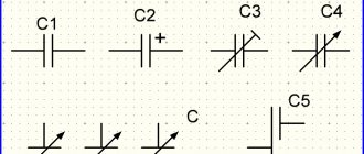
Appearance of an electrolytic (polar) capacitor and its designation in the diagrams
Before testing a capacitor with a multimeter, inspect its housing. If there is no stripe, you don’t have to think about the position of the probes.
Method 2: Measuring LC Oscillator Frequency
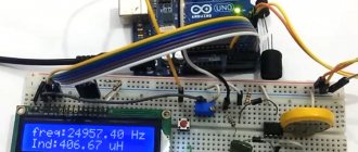
The circuit uses a simple LC oscillator with a comparator. A known capacitance and a known inductance operate in a resonant circuit. An additional one, connected to the relay, allows you to calculate the exact values of L and C of the components used. During measurement, the added external capacitance or inductance changes the oscillator frequency and this change allows the measured value to be calculated.
This circuit comes in several variations, often using comparators built into the microcontroller. The calculation accuracy in the original version is 0.1%. The accuracy of the calibration depends on the accuracy of the calibration capacitor.
Measuring instruments
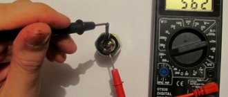
The most accessible method for measuring capacitance is a widely used multimeter with this capability.
In most cases, such devices have an upper measurement limit of tens of microfarads, which is sufficient for standard applications. The reading error does not exceed 1% and is proportional to the capacity. To check, just insert the capacitor leads into the intended sockets and read the readings; the whole process takes a minimum of time. This function is not present in all models of multimeters, but it is often found with different measurement limits and methods of connecting the capacitor. To determine more detailed characteristics of the capacitor (loss tangent and others), other devices are used, designed for a specific task, often stationary devices.
The measurement circuit mainly implements the bridge method. They are used limitedly in special professional areas and are not widely used.
Method 3: Capacitance Measurement Using CTMU
The CTMU, or Charge Time Measurement Unit, is a module found in many PIC microcontrollers, primarily designed to control keyboards and touch interfaces. The module also allows accurate capacitance measurements by measuring the voltage across the capacitor under test, fed from a current source over a specified period of time. The operation of the system is based on the charge formula:
Since we know the current I and time t, and can measure the voltage V, we can calculate the value of C. The working method is shown in the figure below from the AN1375 documentation. Here you can see how to calibrate and measure capacitance.
Prerequisites for accurate absolute capacitance measurements are an accurate calibration of the current source, a relatively accurate microcontroller timer, and a good reference signal source for the ADC. The current source can be easily calibrated - simply connect an external precision resistor and measure the voltage applied to it. By the way, precision resistors are easier to find than precision capacitors.
But direct measurement of capacitance has another drawback - the entire circuit is loaded with various parasitic capacitances. Therefore, it is recommended to permanently connect a capacitor in parallel with the measuring input, take measurements and use this value as “zero”.
Sequence of steps:
- Generate and calibrate the current source using the ANx input and resistor.
- Switching to the ANy input and discharging the circuit capacitance.
- The timer starts the current operation of the source, measures the specified time, and stops the source. The ADC performs the measurement.
- An external capacitor is connected, steps two and three are repeated.
- If the ADC value is close to zero, repeat the entire measurement with a higher current or longer time. When the value is close to the maximum value, the measurement time is reduced.
- The results of both measurements are converted to picofarad values.
- The result of the first measurement is subtracted from the result of the second to subtract the stray capacitances of the circuit.
- The result is formatted and shown on the display.
The CTMU current source has four possible values: 0.55 µA, 5.5 µA, 55 µA and 550 µA and is adjustable over a range of 0.341 µA for the main range in 0.011 µA increments. Measuring a large capacitance will require increased source charging time, but such a meter should have a decent accuracy of 0.1% and a measurement range from units of picofarads to thousands of microfarads. When measuring large capacitances, it may be necessary to add an external transistor to discharge the capacitance, since the internal transistor may not be able to handle large currents.
By labeling
Recall that the SI unit of capacitance is the farad (denoted F or Ф). This is a very large value, so in practice submultiples are used:
- millifarads (mF, mF) = 10-3 F;
- microfarads (µF, uF, mF, µF) = 10-3 mF = 10-6 F;
- nanofarads (nF, nF) = 10-3 μF = 10-9 F;
- picofarads (pF, mmF, uuF) = 1 pF = 10-3 nF = 10-12 F.
We have listed the name of the units and their abbreviation because they are often found in the markings of large capacitors (see Fig. 6).
Rice. 6. Marking of large capacitors
Pay attention to the marking of the flat-plate capacitor (second from the top): after the three-digit number there is the letter M. This letter does not indicate the unit of measurement “megafarad” - these simply do not exist. The letters indicate tolerances, that is, the percentage of deviation from the capacity indicated on the body. In our case, the deviation is 20% in any direction. The inscription 102M on a large case could be written: 102 nF ± 20%.
Now let’s decipher the inscription on the body of the third product. 118 – 130 MFD means that we have a capacitor whose capacitance is in the range of 118 – 130 microfarads. In this example, the letter M already stands for “micro”. FD – stands for “farads”, an abbreviation of the English word “farad”.
This simple example shows how much confusion there is in labeling. The coding used for tiny capacitors is especially confusing. The fact is that you can find capacitors whose markings are done in the old way and parts with modern coding, in accordance with the EIA standard. The same symbols can be interpreted differently.
According to EIA standard:
- Two numbers and one letter. The numbers indicate the capacitance, usually in picofarads, and the letter indicates the tolerances.
- If the letter appears in the first or second place, then it denotes either a decimal point (symbol R) or indicates the name of the unit of measurement (“p” - picofarad, “n” - nanofarad, “u” - microfarad). For example: 2R4 = 2.4 pF; N52 = 0.52 nF; 6u1 = 6.1 µF.
- Marking with three numbers. In this code, pay attention to the third digit. If its value is from 0 to 6, then multiply the first two by 10 to the appropriate degree. In this case, 100 =1; 101 = 10; 102 = 100, etc. up to 106.
Numbers from 7 to 9 indicate an exponent with a minus sign: 7 conditionally = 10-3; 8 = 10-2; 9 = 10-1.
Example:
- 256 means: 25×105 = 2500000 pF = 2.5 µF;
- 507 stands for: 50×10-3 = 50,000 pF = 0.05 µF.
The following inscription is also possible: “1B253”. When decoding, you need to break the code into two parts - “1B” (voltage value) and 253 = 25 × 103 = 25,000 pF = 0.025 µF.
The code marking uses capital letters of the Latin alphabet to indicate tolerances. We looked at one example by analyzing the markings in Fig. 6.
Here is a complete list of symbols:
- B = ±0.1 pF;
- C = ±0.25 pF;
- D = ±0.5 pF or ±0.5% (if capacitance exceeds 10 pF).
- F = ± 1 pF or ± 1% (if capacitance exceeds 10 pF).
- G = ± 2 pF or ± 2% (for capacitors from 10 pF").
- J = ±5%.
- K = ± 10%.
- M = ± 20%.
- Z = -20% to + 80%.
Products with code marking are shown in Fig. 7.
Rice. 7. Example of code marking
If the encoding does not contain a character from the list above, but contains another letter, then it may be a unit of measurement of capacity.
An important parameter is its operating voltage of the capacitor. But since in this article we set the task of determining capacity, we will skip the description of voltage markings.
You can distinguish an electrolytic capacitor from a non-polar one by the presence of the “+” or “–” symbol on its body.
Color coding
It makes no sense to describe the meaning of each color, as this is clear from the following table (Fig. 8):
Rice. 8. Color coding
It is quite difficult to remember the symbolism of code and color markings. If you do not have to constantly select capacitors, then it is easier to use reference books or refer to the information presented in this article.
Method 4: Capacitance measurement using an external current source
This method requires three Vbe and gain matched PNP transistors connected together for thermostatics, and several resistors with 0.1% accuracy. Let's look at the diagram:
Resistors R1-R3 and transistors Q1-Q3 form a current mirror. Resistors R4 - R8 are connected to the digital outputs of the microcontroller. By setting one of them low while the others are in a high resistance state, you can select one of five current values: 1 µA, 10 µA, 100 µA, 1 mA and 10 mA. In turn, setting one of the outputs connected to R9, R10 or R11 low allows the current generated by the source to be measured by measuring the voltage across the corresponding resistor.
Q4 and R12 are used to discharge capacitance between measurements. The measurement is exactly the same as for the CTMU method. We select the charging current, measure the specified time, stop the current, measure the voltage on the capacitor. If necessary, change the charging time or charging current.
Measurements by this method are limited only by the resolution of the ADC, the stability of the reference voltage and the accuracy of the resistors. By connecting a multimeter instead of Cx, you can pre-calibrate all ranges. Most inexpensive multimeters have fairly accurate current ranges, although measuring voltage across resistors R9-R11 may be more accurate.
Designations on capacitors
The easiest way to determine the capacitance value is by the markings on the capacitor body.
Electrolytic (oxide) polar capacitor with a capacity of 22000 µF, designed for a nominal voltage of 50 V DC. There is a designation WV - operating voltage. The marking of a non-polar capacitor must indicate the possibility of operation in high voltage alternating current circuits (220 VAC).
Film capacitor with a capacity of 330000 pF (0.33 µF). The value in this case is determined by the last digit of a three-digit number, indicating the number of zeros. The following letter indicates the permissible error, here - 5%. The third digit can be 8 or 9. Then the first two are multiplied by 0.01 or 0.1, respectively.
Capacitances up to 100 pF are marked, with rare exceptions, with the corresponding number. This is enough to obtain data about the product; the vast majority of capacitors are marked this way. The manufacturer can come up with his own unique designations, which are not always possible to decipher. This especially applies to the color code of domestic products. It is impossible to recognize the capacity by erased markings; in such a situation, you cannot do without measurements.
Method 5: Capacitance Measurement Using CVD Module
The CVD module, a capacitive voltage divider, can be found in some PIC microcontrollers. This is another Microchip idea for creating touch keyboards, such as the PIC18FQ41 family.
Interestingly, measurement with this method can be performed without this module by manipulating the configuration bits of the microcontroller's port and its ADC module, respectively.
Suppose there is a capacitor with a capacity of 1 nF, charged with a voltage of 5 V. Let's connect a second capacitor with a capacity of 1 nF to it. What voltage will both have? The correct answer is 2.5 V. Now let's take two other capacitors: 10 nF and 22 nF. The first is charged at 5 V, the second is shorted to ground. Then we connect them both together. What will the voltage be? 1.5625 V. Now let's charge the second capacitor to 5 V, discharge the first and connect two. What will the voltage be? 3.4375 V. The CVD module makes this exact measurement, with the ADC sample capacitor (plus any additional capacitors connected inside the microcontroller) acting as capacitor 1, and whatever is connected to the ADC pin where the measurement is being made as capacitor 2.
The CVD module first automatically loads the internal capacitance, connects the external capacitance and measures it, then discharges the internal capacitance, charges the external capacitance and performs a second measurement. The results are automatically subtracted from each other, and the resulting value is compared with a specified threshold - so the module is mainly used to control touch buttons, but you can also measure the value of an attached external capacitance as a change in differential voltage. But here the measurement will be less accurate than the CTMU measurement.
Parallel inclusion of a working component in the circuit
Another way to check a capacitor without desoldering is to connect a known-good analogue of the same capacitance in parallel with it. If the device works, then the problem really was in the capacitor and it needs to be replaced.
This test method cannot be used in high voltage circuits.
Checking for spark
If you don’t have a measuring device at hand or if the capacitor capacity is large, you can check it “by eye”.
The element is charged, then a metal tool with insulated handles is used to short-circuit its terminals. You should wear rubber gloves on your hands.
A bright spark accompanied by a characteristic sound indicates that the capacitor is working properly. If the discharge turns out to be sluggish, it is time to dispose of the radio component.
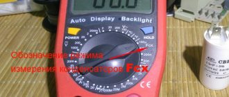
To obtain comprehensive information about the condition of the capacitor, you need a multimeter with a capacitance measurement function (there is a “CX” sector on the control panel).
But even a tester not equipped with such an option will tell a lot about this element. Removing the capacitor from the board is not always necessary, but you should be prepared for the fact that when taking measurements on the board, the accuracy will be far from ideal.
Why is a high ESR value harmful?
At zero frequency (direct current) and low frequencies, as you remember from the article, the capacitor itself offers great resistance to electric current.
In this case, some parasitic Ohm fractions of the ESR resistance will not affect the parameters of the electrical circuit. All the fun begins when the capacitor operates in high-frequency (HF) circuits. You and I know that a capacitor passes alternating current through itself. And the higher the frequency, the lower the resistance of the capacitor itself. Here's the formula in case you forgot:
where XC is the resistance of the capacitor, Ohm
P is a constant and equals approximately 3.14
F - frequency, measured in Hertz
C - capacitance, measured in Farads
But we didn’t take one thing into account... The resistance of the leads and plates does not change with frequency! So... and if you think about it, it turns out that at an infinite frequency the resistance of the capacitor will be equal to its ESR? It turns out that our capacitor turns into a resistor? How does a resistor behave in an AC circuit? Yes, just like in a DC circuit: it gets hot! Therefore, this resistor will dissipate power P into the environment. And as you remember, power through resistance and current is expressed by the formula:
P=I2xR
Where
I is the current strength, in Amperes
R - ESR resistor resistance, in Ohms
This means that if the ESR is greater, then the power dissipation will also be greater! That is, this resistor will heat up quite well.
Are you catching up on what I’m telling you?
