Advantages and disadvantages
A DIY external antenna for a car radio can be mounted at home under any vehicle body.
Such mechanisms do not have any problems with the installation height for receiving an FM signal. Another advantage of a homemade device is the better quality of signal reception compared to factory-made mechanisms. If necessary, the user can convert it into a GPS antenna. The disadvantages include the fact that employees of the state road safety inspection may have questions about a homemade antenna. Wires from the receiving mechanism can damage the interior of the cabin. In some cases, it may be necessary to drill into the body to install this unit.
How a car antenna works
Such a device is necessary to receive electromagnetic waves. It begins to convert the energy flow of these waves into an electrical signal. After these manipulations, this signal can be amplified and converted. Reception of such waves is possible only when the antenna is tuned to the required frequency or frequency range.
In order for it to capture the required frequency range, you need to choose the right length, because The quality of the received signal and sound will depend on this. In order for the device to pick up FM frequencies, the antenna must be at least 750 mm long. This explains the relationship between the size of the device and the quality of the resulting sound.
To make an antenna for a radio with your own hands, you should first decide on the type of mechanism.
There are several types, each of which is used for its own purposes.
For example, an active antenna is an electronic mechanism that combines a radio wave receiver and a radio frequency amplifier. It is capable of processing a weak signal that is sent to the canvas, then to the body of the amplification device, after which it is transmitted via cable to the antenna input of the car radio installed in the vehicle interior. Passive antennas can only receive signals from local stations.
Recommendations
If we talk about recommendations for the creation and use of such antennas, then first of all we should note several.
- There should not be any metallic foreign objects near such a device. Otherwise, they may interfere with the reception of the signal or reflect it, which will also negatively affect the quality of its reception.
- Care should be taken to protect the antenna from exposure to natural factors. Otherwise, its parts may rust and sooner or later the device will simply fail.
- In most cases, it is necessary to make drawings before starting work, where you need to describe in detail the dimensions and dimensions of the device, its type, as well as the algorithm of actions for its creation. This will make it possible to quickly and accurately implement one or another idea and obtain a high-quality antenna for receiving a stable FM signal.
How to make a radio antenna with your own hands in 15 minutes, see below.
Sources
- https://electrikexpert.ru/kak-sdelat-antennu-dlya-radio-fm-svoimi-rukami/
- https://amperof.ru/elektropribory/antenna-dlya-radio.html
- https://homius.ru/antenna-dlja-radio-svoimi-rukami.html
- https://stroy-podskazka.ru/radiopriemniki/antenna-svoimi-rukami/
Varieties of the model range
Anyone who has decided to build an antenna for FM radio with their own hands must understand that the main task of such a device is to capture the broadcast signal, amplify it and transmit it to the input of the receiver being used. Depending on the required range, the final unit may differ not only in the type of design, but also in dimensions. Experienced experts say that the modern market has a huge variety of antennas, and some of them can easily be called complex engineering structures that can occupy up to several thousand square meters.
In the standard model, the receiving device can be equipped with a universal conductor, which is suspended above the ground surface on protective insulators. Those electromagnetic waves that cross such a unit induce a high-frequency alternating voltage in it and transmit it to the input of the radio receiver. The final device amplifies the signal, due to which a specific low-frequency component is isolated from it, and the user himself hears high-quality sound.
Peculiarities
Despite the fact that today computers or at least televisions are very popular, there are still fans of radio broadcasting. In order for an FM radio to fully and correctly perform all its functions, it must be equipped with a specially designed antenna. Currently, the technology market offers a large number of types of antennas that provide high quality signal reception. They vary in size, appearance and functionality. Let's look at a few of the most common options:
- rod devices are made in the form of an ordinary rod or have a rounded shape;
- wire antennas are curved;
- the design of telescopic units consists of special metal rods, which in appearance resemble telescopes (hence the name of this type);
- retractable units are most often installed in cars; they have a special retractable design with a receiving element.
How to make a car antenna yourself
Some car antenna models are relatively expensive. The main part of the cost of antenna devices is not materials, but design and circuit design. The slightest deviation from the design design or manufacturing technology can lead to a significant change in the antenna parameters.
Considering that if you make it yourself, you can reproduce the design design with high accuracy and perform high-quality installation, you can expect high parameters from an antenna made by yourself. Moreover, the cost of the finished product can be much lower than the factory version.
What function does it serve?
The only function of an external (additional) antenna is to increase the reception range in areas of very weak radio communication. This is how long-range and ultra-long-range techniques are implemented. Car antennas are in great demand among truckers who need high-quality communications and reception over many tens of kilometers. Radio stores often sell antennas with a very short pin - only 10-25 cm. A non-professional, who does not particularly understand radio as such, takes what they give - he does not realize that if the pin is increased to the required length, the reception quality will noticeably improve .
A tribute to the fashion for miniaturization and lightness of any devices takes over - as a result, the quality is far from expected.
How to make a car antenna with your own hands
For radio
An antenna for a car radio can be made from any steel pin. In order for it to work well over the entire wavelength range, from medium (AM) to ultra-short (FM), it is necessary to install an inductive extender of effective length. It represents a regular inductor coil wound with thick copper wire in varnish insulation. Such a wire can be taken from the step-down winding of an old powerful transformer.
In order for the winding to be sufficiently even, it is wound on a long key with a thread pitch approximately equal to the diameter of the wire.
The end of the wire is stripped and secured under the washer on this key, as shown in the figure.
The inductance is usually wound with a length of more than 20 centimeters. If desired, you can attach (preferably weld) a steel elastic extension rod up to 50 cm long to its end. Next, the resulting structure is filled with silicone. In principle, the antenna is ready, it can be installed as a mortise device in a regular place in the car. To improve the design, it can be placed in a black cambric of the appropriate size.
Despite its ease of manufacture and small size, the antenna has high efficiency over a wide frequency range.
For TV
A TV antenna is usually made in an active version, that is, with an amplifier. Most residents in rural areas and summer residents have experience installing external antennas with an amplifier on the antenna. This experience can be used to make a television antenna for a car. To do this, you will need a piece of copper wire up to 1 meter long, a coaxial cable, two connectors for connecting to a TV and an antenna, a standard (usually Polish) active antenna amplifier and a standard galvanic isolation (power adapter).
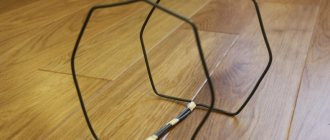
The simplest and at the same time effective television antenna is shown in the figure.
To make it, you only need copper wire and a standard television connector. The rib length is usually selected from 80 to 120 mm. This antenna is designed to receive decimeter waves. In the same range there are digital television broadcasting stations (for connection to a DVB-T2 receiver).
The antenna can be carefully attached to the windshield using suction cups. You can independently experiment with the shapes and sizes of the antenna frame. Sometimes you can unexpectedly get a high-quality antenna with minimal dimensions.
For an amplifier with power decoupling, you can assemble a standard circuit similar to an antenna device for a stationary TV.
1 – car TV connector (may be of a different type);
2 – galvanic isolation unit for power supply (it can be purchased separately, it is sold together with the power supply for antenna amplifiers);
3 – cable for power connection;
4 – standard antenna amplifier for stationary TVs (the type is selected based on the distance to the transmitting station in the vehicle’s operating area).
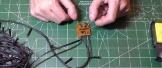
It is better to mount the circuit using soldering.
The structure is placed in a suitable housing and installed near the antenna.
The manufactured antenna amplifier is also suitable for a radio receiver operating in the FM range.
For walkie talkie
The most difficult thing to make is an antenna for a car radio. More precisely, not to manufacture, but to configure. The tuning process requires special equipment, such as a standing wave ratio (SWR) meter. If you deviate even slightly from the dimensions of the antenna design or the proposed cable length, then the powerful high-frequency signal emitted by the radio transmitter will “return” back to the radio station without reaching the airwaves, which can lead to its breakdown.
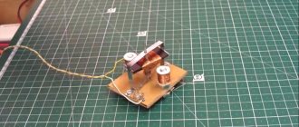
The emission, propagation and reception of electromagnetic oscillations is studied by a science called electrodynamics. It is not simple, so to make your own antennas for walkie-talkies, it is better to use someone else’s experience. There are many interesting designs on the Internet, for example, the one shown in the figure.
For this design, you can use a factory whip antenna by installing it on a homemade rod with a wave extender wound on an insulator.
Good antennas for walkie-talkies are expensive, but they can be made from readily available components.
What power steering fluid should be used and how to replace it.
See how a 12-220V car voltage converter works and when it comes to the rescue.
How to connect https://voditeliauto.ru/poleznaya-informaciya/avtoustrojstva/akb/vyklyuchatel-massy.html car mass switch and in what cases its use is not advisable.
Video - making an CB antenna from scrap materials:
DIY FM antenna for music center
If the factory version does not satisfy the user for the reasons described above, then he should try to make his own antenna for his music center. To make homemade devices for receiving radio signals, you will need different raw materials.
Made of metal foil in the form of a square
In order to make a receiving device from foil, you will need:
- Fiberboard or small board.
- Roll of metal foil.
- A piece of shielded cable with a resistance value of 50–75 ohms.
- The plug required for connecting to the MC.
- Soldering iron and accessories (solder, flux).
This is one of the easiest homemade antennas to make. You need to cut out a square frame of the required size from foil. A 15 mm wide cutout is made in its lower part. After this, the frame must be fixed to a piece of fiberboard using ordinary glue. When the foil is glued, a “screen” and the central core of the wire are soldered along the edges of the cutout at the bottom of the frame. The gap between the soldering points of the wire should be within 25–40 mm.
Such an FM antenna can be installed both indoors and outdoors, if the cable length allows it. In order to “adjust” the received signal, the device is slowly rotated around its axis.
From pipes
This design is based on the use of conventional pipes used for utilities at home. In addition to these you will also need:
- disassemble the line transformer of an outdated tube TV and remove the ferrite core from it;
- purchase glue and high-quality electrical tape;
- buy a roll of brass or copper foil;
- get a copper installation cable with a cross-section of 0.25 mm and a length of one and a half meters;
- prepare a plug with which the antenna will be connected to the MC.
First of all, paper and electrical tape are placed on the ferrite core of the transformer in two layers. After this, the foil is laid on top of the electrical tape in one layer, while overlapping the turn by 1 centimeter. It is necessary to ensure that the two sides of the coil are not in contact, and periodically prevent possible contact using electrical tape. A wire with taps on the seventh, twelfth and twenty-fifth turns is wound onto the finished screen at 25 turns.
In the same way, the prepared communication circuit is wrapped with a “screen”. The screens are subsequently connected to each other, and the ends of the cable are inserted into the plugs.
From coaxial cable
Such antennas are well suited for areas with unstable signal. For their manufacture they are usually used:
- one and a half or more meters of TV cable;
- a one and a half meter plastic tube, about 20 mm in diameter;
- wooden mast.
To begin, at a distance of about 75 centimeters from the end of the cable, you need to cut the wire and carefully remove the plastic insulation from it, without damaging the integrity of the braided screen. The braid must be kneaded, after which, being careful not to damage the copper core, turn the screen towards the cut.
Then, using any available methods, the antenna is fixed inside a plastic pipe, and after that the pipe is attached to a wooden mast. Searching and capturing the signal is adjusted by vertical rotation of the mast, as well as the height of its installation.
If the shielded cable was not damaged during the assembly of the device, then such an antenna will be able to operate with a minimum amount of interference.
Voice radio in the country: ways to strengthen the signal
In a suburban area, receiving radio broadcasts and music is good entertainment, including during gardening work. Unfortunately, in practice, many are faced with the fact that the receiver produces a large amount of interference. Sometimes the signal is completely lost, and it is simply impossible to find your favorite radio station by setting the slider to the desired wavelength range. All this indicates poor reception, which can be improved in simple ways.
Build up your antenna
No matter how you receive a radio signal, it requires an antenna. If we are talking about a receiver with a folding pin that is hidden in the case, then its size is often not enough, especially if we are talking about a place far from the city, where the reliable reception zone disappears. In this case, you need to make the antenna longer and raise it higher. In a private house, this is done very simply - a pole is fixed on the roof with a piece of wire, stripped of insulation, tied to it. The material for receiving the signal is not important - it can be either copper or steel.
Make a reverb
The simplest device that amplifies a radio signal is nothing complicated. It should be made in the form of a frame, usually triangular or square, made of three meters of copper wire stripped of insulation. In some cases, it can provide stable reception at a distance of 150 km from the city. One end is connected to ground, the other to the central output of the antenna socket.
Connect amplifier
This device is usually a box that is connected to the antenna frame. Inside the case there is an amplifier chip with active power supply. In order for the circuit to work, you need to plug in an adapter that produces 12 V DC. A cable comes from the amplifier, which connects to the FV receiver. This method is most widely used for receiving television signals, but where television broadcasts are received, the radio will be heard just fine.
The listed methods do not exhaust the possible recipes for amplifying a radio signal under various conditions. Radio amateurs on forums willingly share their inventions, and not all of them are difficult to manufacture.
Assembly instructions
You can make both inactive and active (with an amplifier) devices with your own hands. The production technology consists of several stages:
- preparing the necessary tools;
- direct assembly;
- fastenings to the machine body;
- connections.
Assembling different types of antennas for a radio with your own hands differs significantly even in the selection of necessary tools.
Production of an inactive installation
Passive antennas without an amplifier are considered quite simple in design. To create such a device, you will need:
- copper wire (diameter from 1.5-2 mm);
- high quality nut;
- good file;
- screwdriver;
- thermal glue (can be replaced with heat shrink tube);
- screw (diameter M5);
- lock-nut.
Assembly is carried out in stages. For this:
- Take copper wire and twist it to a length suitable for a particular car.
- The resulting spiral is placed on an M5 screw, secured with a nut and a lock nut of the same size (soldered on top). The structure is treated with thermal glue, or wrapped using heat shrink tubing.
- The surface is sanded with a file. This procedure is done provided that the spiral has been treated with glue (only after the substance has completely dried).
- Install a homemade antenna. The spiral blank is inserted into the hole made (at the base), and the wires are connected.
To give the installation an aesthetic appearance, a film is glued onto it, treated with a primer, and painted. The passive device is ready.
Creating an active fixture view
A special feature of this technique is the presence of equipment that enhances signal reception. When creating internal active installations, frame structures are used. This requires the following tools:
- copper wire, always with insulation (diameter - 2 mm);
- home amplifier (a television device will do);
- high-quality soldering iron;
- a connector that is suitable for a radio;
- good nippers;
- glue.
An amplifier housing designed for a regular home antenna is often used as the basic basis for the device. Solder a wire to it, which, in turn, will connect to the radio. This is necessary for the amplifier to receive and transmit signals.
The antenna plug is connected to the socket, and a connector is mounted at the other end of the wire. The power cable for the amplifier in car radios is considered the control cable; it is painted blue.
An active type receiver is mounted on the roof of the car so that signals are well received. To do this, two holes are drilled in the housing - mounting and auxiliary. The antenna wire is laid around the perimeter of the driver's door, fixed with glue. After installation on the roof of the car, attach the (side) cable to the rack and carefully connect it to the car radio.
Installation and connection features
Traditionally, active types of antennas for radios are installed on windshields in the upper right corners or behind rear-view mirrors. Passive installations for receiving signals are placed on car bodies, usually mounted on roofs.
Any antenna should be mounted only on a clean surface. For installation, use glue or masking tape, bolts, nuts, lock nuts for grounding, and a drill suitable for the diameter of the antenna wire. The mounting area must be degreased with a special cleaner.
Fix the devices with glue or masking tape. After installation, wires are laid from the antenna to the radio. This is done either around the perimeter of car doors or windows, or directly around the interior through special openings.
The design of an ordinary car antenna has three wires:
- The first is used to ground the device. It attaches to a metal mount on the body. Secure the wire with a bolt, a strong nut and a lock nut.
- The second is used to power the device. It is connected to the wire coming from the radio.
- The third is a contact one; it is connected to a specially designed connector.
Most often, the second wire is combined with the third; by connecting the power, the contact function is activated, and the antenna begins to receive the signal.
AUGRA installation options
Installation of automatic control gear must comply with the following requirements:
- ensuring reliable fastening of the radio receiver to the car, preventing movement when exposed to various mechanical loads (wind, bending, etc.);
- ensuring tight contact with the body, which acts as a mass, which significantly reduces the level of interference and improves signal quality.
DIY Mimo 4g lte antenna
All options for installing a receiving radio antenna come down to three main methods for fixing the automatic control gear on a vehicle:
- mortise mounting using a through hole drilled in the roof or other part of the body;
- magnetic mount using a magnetic antenna base;
- a pin mount, which is a mechanical fixation of the antenna rod for a car radio on a special clamp-type bracket.
APRA mortise mount
The mounting pin of the radio antenna base is inserted into the through hole, and a nut is screwed onto it from inside the passenger compartment. The advantages of the “mortise fastening” method include:
- the strength of the device, reducing the likelihood of it being stolen;
- stability of the operating parameters of the antenna-feeder system after installation.
Among the disadvantages, the following circumstance is noted: the edges of the drilled hole are centers of corrosion of the metal body, therefore it is recommended to use standard technological holes.
Important! In the fastening area, it is necessary to strip the metal of paint to ensure reliable conductive contact of the nut, as an element of the antenna, with the metal of the car body. On rice
Below is the antenna base with a pin and a hole in the roof of the car prepared for installing the AUGRA
In Fig. Below is an antenna base with a pin and a hole in the roof of the car prepared for installing the AUGRA.
Antenna base for flush mountingMagnetic mount APRA
The magnetic fastening of the antenna is provided by magnets located at its base - the sole. Magnets can be purchased separately from the antenna device. The most popular magnets are with diameters from 90 to 170 mm. The stability of the automatic control gear directly depends on the diameter of the magnet.
The antenna is attached to the magnet through two types of connectors:
- The DV connector is adapted to most antenna systems and allows for adjustment of the installation angle;
- The PL connector is more reliable in terms of maintaining strict vertical installation.
In Fig. Magnetic antenna mounts with DV and PL bases are shown below.
Magnetic antenna mounts with DV and PL bases
The advantages of the magnetic fastening method include the following points:
- ease of installation or dismantling;
- relatively high stability of the automatic control gear is ensured while maintaining the optimal size of the magnetic base;
- capacitive coupling of the magnetic base with the metal of the body creates a kind of imitation of “mass” necessary for the operation of the receiving antenna;
- the ability to move when setting up equipment.
Disadvantages include:
- low strength of fixation on the body;
- ease of abduction;
- the possibility of shifting, which leads to the need for additional adjustments.
APRA pin mount
For the technical implementation of the pin fastening, a clamp bracket is installed on the protruding part of the car body (fender, trunk, etc.), the clamping bolts of which, with their pointed ends, create mass contact necessary for high-quality radio reception.
In Fig. The pin mount on the bracket is shown below.
Pin mount
One of the advantages of this method is the possibility of fixing antenna devices on vehicles with non-uniform and protruding metal surfaces (truck cranes, open cars, special equipment).
The disadvantages include:
- low mechanical strength;
- difficult setup and coordination of automatic control gear.
DIY pipe antenna
The main supporting element of this radio antenna is heating or water pipes. Required materials for creation:
- used transformer core (from an old TV);
- electrical tape, tape, office glue;
- foil made of thin copper or brass;
- one and a half meters of copper wire (diameter ¼ sq. mm);
- connecting pins.
For winding, the first layer is a ferrite core, a couple of layers of electrical tape on top, followed by a single foil layer. Exactly 25 turns of wire are wound onto such a screen blank with an overlap of 1 centimeter for better contact insulation. You should remember about the mandatory taps on turns No. 7, 12 and 25. The circuit is connected to other parts, and the ends of the wire are inserted into the pins. The tap from the 7th turn is inserted into the grounding socket, and the remaining two are connected to the antenna terminals.
The final stage is setting up the radio signal reception; this is done by simply selecting the connection of the winding to the connected circuit. Such homemade radio antennas reliably receive a signal even in a severe thunderstorm, thanks to reliable grounding.
If the radio receiver is located in an area where the reception is very weak and of poor quality, you can assemble an omnidirectional antenna yourself using a coaxial cable. For this you need:
- wooden slats;
- one and a half meters of cable (television cable is best);
- one and a half meters of PVC pipe (section diameter 2 cm).
Homemade antenna from coaxial cable
It is quite simple to construct such an antenna
A cut is made on the wire to remove the insulating layer (but the braid must remain intact, this is important!). Having loosened and slightly stretched the braid, the screen is turned out to the place of the incision
The final stage is to install and securely fasten the antenna inside the plastic tube and mount it on a wooden rail. The adjustment to search for a radio station signal is made in the vertical direction, and not by rotating the homemade antenna 360 degrees.
In dachas, in cars, even in urban built-up areas, those who like to listen to the radio are well aware of the problem of a weak signal and quiet sound of radio transmissions, especially in the FM range. Antennas for radios of various types and types of signal reception help correct the situation. They can be purchased in special stores, or you can make them yourself; fortunately, the technology is simple, and the parts can be bought at any radio market.
Reasons for poor reception of radio stations
The amount of attenuation depends on:
- the distance traveled by an electromagnetic wave;
- transmitter carrier frequency (the higher, the greater the loss) or wavelength;
- state and material of the conducting medium;
- presence of interference in the path of electromagnetic waves propagation;
- quality of regeneration and correction;
- waveforms.
A digital discrete radio signal, passing through a repeater, is most often completely restored without loss of information.
The most common form of interference on transmission lines is crosstalk. The cause of distortion may be equipment malfunctions or insulation cracks. When transmitting signals through wires, pairs are intertwined to eliminate interference.
The shielding properties of wall materials and building decoration can also weaken the radio signal. Strong screen - metal siding, aluminum sandwich panels, corrugated sheet roofs, metal tiles, etc.
Each radio receiver has a built-in antenna. In order for it to confidently perceive the useful signal, separating it from noise and interference, its level must exceed a certain threshold. This value is called the sensitivity of the radio receiver. A good receiver has better sensitivity, but the radio signal level decreases with distance from the transmitting antenna. At a certain distance, reception with the built-in FM antenna becomes impossible.
But even at short distances in the city there are dead zones where the signal fades sharply. Radio waves travel only in a straight line and do not pass through obstacles well. But it has the property of being reflected from them. True, after reflection it loses its power. But the reflected signal, when added to the main one, leads to complete illegibility of the signal from the radio station.
The straight-line propagation of FM radio waves does not allow them to be confidently received beyond the horizon, where the signal from the transmitting antenna is not able to penetrate. It can fall below the horizon, reflected from clouds, but this depends on the weather and still does not help much.
We suggest you familiarize yourself with how permanent markers are washed.
The way out is:
- amplification of the input signal before feeding it to the receiver input;
- selective reception from only one direction;
- raising the receiving point to a certain height.
Triple square
The triple square, also known as the Sotnikov antenna (non-standard radio devices are usually named after the name of the inventor or popularizer), consists of three square frames of variable perimeter:
- directors;
- vibrator - it is from it that the received signal is removed;
- reflector.
This antenna is a development of the principles inherent in the design of the wave channel, but it is much simpler to manufacture. Outwardly, it looks like three squares gradually decreasing in size, mounted on common crossbars so that their axis faces in the direction of the signal source.
In short, it is assembled from steel or copper wire as follows:
- Three main squares and jumpers between them are bent. If necessary, you can immediately bend the entire zigzag assembly according to the attached drawing.
- The joints are soldered together.
- The stripped end of a 75 Ohm coaxial cable is soldered into the split of the vibrator (where the wire ends are connected).
Advantages:
- High sensitivity. This is a good long-range device for receiving a weak signal from a long distance.
- Manufacturability. If you bend it from a single piece of wire, then soldering will only be needed to connect the cable and joints.
- It is possible to connect an amplifier, which turns the structure into an active antenna, ideal for a summer house or country house.
Flaws:
- Not the best radiation pattern. Even a slight bend in the wire leads to losses in the received signal power.
- Extremely narrow focus. A triple square covers no more than 10 channels according to the old layout, so if the multiplexes differ greatly in frequency, you will either have to make two antennas (and solve matching problems) or sacrifice sensitivity.
- To get all the benefits from the range of this antenna, you need an accurate calculation (ideally down to the millimeter).
Types of car antennas
We mentioned the types of car antennas, but here is a redundant classification:
Purpose:
- Radio reception.
- TV reception.
- Reception of satellite information from navigation systems.
- Communication car antennas.
Method of installing antennas on a car:
- Magnetic.
- On a suction cup.
- Mortise.
- Threaded connection.
- On a clamp.
- Built-in.
Connection diagram for a car antenna under the rear fender
By location:
- External car antennas.
- Salon (internal).
Type of gain:
- Active.
- Passive.
Surely an experienced car enthusiast will be able to add a couple of signs, but we will limit ourselves to the specified classification. FM antennas fit inside the cabin. Hobbyists make accessories with their own hands, using pieces of cable with a characteristic impedance of 50 Ohms. The braid is electrically connected to the car body (ground). Be careful of catching lightning while driving through a field. The thunderstorm chooses the point closest to the sky.
The size of the car antenna depends on the range. Communications (walkie-talkies with a frequency of 27 MHz) are large. Powerful varieties reach a length of 2 meters (they are placed on trucks); according to science, they should be made 50 cm higher. To reconcile the differences between the actual size, a quarter of the wavelength is an “extension” coil at the base. For use, the car antenna for communication is installed vertically. Determined by the type of polarization. The communication antenna can be tilted by means of a thumb or lever, so as not to break it when driving through a forest or overcoming the spans of a low bridge. Communication antennas are mostly used by drivers of large trucks. It is allowed to equip jeeps and civilian cars, but at times the appearance will be unsightly.
Note. Factory antennas are tuned to the wavelength. The mustache is shortened, equipped with a protective cap at the end. The operation is carried out according to the instructions. The guide includes a chart of recommended sizes. The violation causes a decrease in reception sensitivity.
The digital car TV antenna looks like a police flasher and is made in a different color scheme. The device is devoid of unnecessary bells and whistles and accepts a frequency of hundreds of MHz. The first multiplex in Moscow chose 559 MHz. The digital car antenna on a magnet is placed on the top (roof), the wire passes over the door without any modifications. A horizontal polarization signal; the device’s task is to receive an arbitrary azimuth.
Broadcasting antennas are rarely boasted of being large, since the wavelength is higher and the dimensions are larger. Small height pins, like those decorating portable radios. Beware of accidentally buying a car radio antenna intended by the manufacturer to decorate a television receiver. For fear of making a mistake, read the technical specifications in the store:
- Radio is designated FM, AM (frequencies 70 - 108 MHz).
- Television - DVB - T (frequencies below 900 MHz).
- Navigation – GPS (about 400 MHz).
- Radio communication – SV (27 MHz).
Sometimes dealers forget to indicate the antenna capabilities. The range of 400 – 530 MHz is given, it is mentioned that “the option of receiving GPS signals is available.” One can only guess what the copy can do; the first Moscow multiplex passes by. Frequencies above 400 MHz are used by portable radios and departmental communications of the Ministry of Internal Affairs.
It remains to pay attention to the connector. Coincides with the vast majority of devices for which it is intended, it would be useful to check the compatibility issue
They say that an external car antenna provides better reception; the question concerns mainly urban reception. While racing along the highway, the windows of a typical passenger car will not create serious obstacles to the passage of electromagnetic radiation. Installation of interior car antennas is simpler. Accessories are lower than external ones, hence the worse quality.
The store will provide all sorts of hybrid models, including options a la All in One. You can switch reception from city to highway. It is distinguished by sensitivity and interference suppression features. The suburban reception range increases to 80 km. They sell unique tandems. A pair of similar looking pins are laid out, one of which picks up television broadcasts, the other – radio, communications. Using the delights of the set requires the purchase of appropriate receiving equipment.
DIY FM antenna
Greetings to readers and subscribers. There are numerous requests in letters and letters to tell us how to make an FM antenna yourself and give an example of such a design with detailed instructions for making a simple FM antenna. In this regard, we publish this article. Three simple FM antenna designs are described here.
Making an FM antenna with your own hands using a design paired with a radio receiver increases the power of the radio signal at FM frequencies (88 - 108 MHz) by 60-100%.
An increase in sensitivity and reception quality is achieved by vertically installing the antenna under the radio wave propagation range of the transmitting antennas. Let's consider the design of three simple antennas. Manufacturing time is from half an hour to three hours.
The construction will require inexpensive or used materials.
FM antenna foil square
Required materials and tools:
- Dried board, fiberboard, dielectric material.
- Metal foil.
- A piece of shielded cable with a resistance of 50-75 Ohms.
- Plug for connecting to a radio receiver.
- Soldering iron, flux, solder.
The manufacturing process of this FM patch antenna is not complicated and takes a minimum of time. A square frame is made from a single piece of foil with the dimensions indicated in the figure and a 15 mm wide cutout at the bottom of the frame. The finished frame is fixed with glue on a flat base made of wood, fiberboard, or any dielectric material.
A “screen” and the central core of the shielded wire are soldered to the bottom edge of the square, to the right or left of the cutout. In the figure, all dimensions are indicated in millimeters, there is no strict reference to sizes, the minimum acceptable size is indicated in brackets, the maximum without brackets. The distance between cable solders (braid and central core) varies from 25 to 40 mm.
Designations: 1 – dielectric material; 2 – foil;
The considered design of a homemade FM antenna is installed indoors or outdoors. The signal is tuned by moving the antenna in the vertical direction and rotating it around its axis.
Tube FM antenna
The antenna design is based on indoor water or heating pipes
Necessary materials:
- Ferrite core from a line transformer of an old tube TV.
- Glue, sticky, insulating tape.
- Brass or copper foil.
- Mounting copper wire 1.5 m with a cross section of 0.25 sq. mm.
- Connecting pins for connecting the antenna to the receiver.
To make the winding, insulating tape or paper is placed on the ferrite core in two layers. A single layer of foil, laid on top of the paper with a coil overlap of 1 cm, is insulated at the overlap area with electrical tape to prevent contact between the two sides of the coil. 25 turns of wire are wound onto the prepared screen with taps at 7, 12 and 25 turns.
The resulting communication circuit is wrapped with a screen by analogy with step 1, followed by connecting the screens to each other. The ends of the wire are inserted into the connecting pins. The connection of the 7th turn pin with the screens is connected to the “grounding” socket of the radio receiver, the remaining pins are connected to the “Antenna” terminal.
The reception setting is made by selecting the connections of the windings of the communication circuit.
Reliable grounding of such an FM antenna using in-house heating pipes allows you to receive transmissions during a thunderstorm without the risk of equipment damage. Vertical installation of pipes in a high-rise building increases the power of the radio signal by 1.5-2 times.
Installation of a radio signal catcher
Installation of an outdoor horizontal antenna begins with the selection of supporting structures. You will subsequently attach insulators to them with your own hands. One of the supports must be installed on the roof of the house. It needs to be reinforced with guy wires. A tree of suitable height can be used as a second support. Insulators can be installed on construction sites using steel cables.
You must attach the outer part of the FM antenna to the insulators with your own hands. It does not need to be subjected to great tension. The wire shrinks if the air temperature is low enough and may lose integrity at low temperatures. Roller blocks will eliminate unnecessary vibrations. To use them, place a small weight on the other end of the wire. It will be connected to the FM antenna if you throw it through the insulator and block.
The receiving part of the antenna must consist of one piece of homogeneous material. If you do not have a homogeneous wire, it is better to construct an FM antenna from separate identical elements. They need to be cleaned and soldered with tin. Equipment for vertical descent of the antenna does not present serious difficulties
Please note that the wire should not be connected to foreign elements. You need to fix the antenna wire with your own hands on a special pull-out stand
This will prevent it from being in the wrong position in windy weather.
If the space for installing an FM antenna with your own hands is limited, you need to use a different design. These are several pieces of wire that look like a “broom”. They will be securely connected by a cable at their lower ends. The ends of the wires can be tightly filled with molten tin. You must cover the soldering area with reliable insulation in the form of bitumen or similar material.
A DIY indoor antenna will be the best option to replace an external catcher. Insulators must be fixed indoors. Their location closer to the ceiling will give an advantage in the quality of signal reception. The wire should be stretched horizontally or rolled into a spiral.
How to make a frame structure?
An aluminum hoop with a diameter of 77 cm and an internal diameter of 1.7 cm can be found in almost any sports store. Plumbing pipes made of a combined metal and plastic structure are well processed. A copper tube with a slightly smaller diameter (16 mm) is also suitable for a radio.
Antenna Rakhmattulaeva
The design of the radio antenna is quite simple.
- The central core, braid and a short piece of coaxial cable must be soldered to the contacts of the variable capacitor.
- The other end, the central core and braid, must be soldered to an aluminum hoop. You can also use car clamps, which need to be thoroughly cleaned, with a diameter of 16-26 mm. The contact area also needs to be thoroughly cleaned.
- The ratio of the frame circumference to the communication loop circumference should be 1:5.
- From the end of the coaxial cable, as well as from the central core, you need to remove the outer insulation to a length of 1 cm with your own hands.
- From the middle of the cable for the FM antenna, you need to measure half a centimeter in both directions and remove the outer insulation. After this, the cable braid must be removed. This will lead to its rupture.
- Check the range of the transceiver device so that the frame has a resonance from 5 to 22 MHz. With other capacitor capacities, you can change the parameters of the transceiver device.
- If you are more interested in low frequency ranges, it is better to use a frame with a larger diameter - 1 or 1.5 meters. If high-frequency - 0.7 meters.
This solution is a simple option to obtain a resonant antenna capable of operating in many bands. Its radiation pattern will be the figure 8. Antennas made of aluminum and copper work approximately the same.
We have brought to your attention popular types of radio antennas that you can make yourself. Most of these solutions are simple enough to make at home, and their ease of setup will allow you to easily cope with the most complex problems.