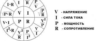
Most electrical processes occur in wires in accordance with Ohm's laws. In accordance with time-tested formulas, it has been confirmed that the current strength in the conductors directly depends on the voltage in the network, as well as the load created by the resistance.
It is impossible to give an exact and unambiguous answer to the question of how to increase the current strength. In fact, this value depends on a number of parameters. But in order to understand the problems of the issue more deeply, we suggest that you recall a little the basics of electrical engineering.
Current strength as one of the parameters of an electrical circuit
Before you try to understand and find out how to increase the current in a circuit, and also understand whether this can be done practically, you need to understand what electric current is. In fact, it is a directed, ordered movement in one direction of charged particles located inside a conductor. A prerequisite for ensuring such movement is the presence of a closed loop.
Positively charged electrons and free ions move inside the conductor. It is important to understand that such movement does not occur without accompanying physical phenomena and processes, namely, heating of the conductor, as well as a chemical effect on the material.
What is current and voltage
We will not dive deep into physics, but will understand the very principle of electric current.
Electric current is the ordered movement of charged particles (both positive and negative, depending on the substance)
.
What kind of particles are moving? In conductors (copper, aluminum, gold, iron, etc.) these are electrons, in electrolytes - ions, in an electron-hole system (in semiconductors) - electrons and holes (positively charged particles). An electron is a negatively charged particle that revolves around the nucleus of an atom. Therefore, negatively charged particles - electrons - move in conductors.
Electrons in a conductor actually move not from plus to minus, as is commonly believed, but from minus to plus, because unlike charges repel.
Some atoms have electrons that are free and can move to another atom.
Atoms of different substances may lack or have an excess of electrons. Then, when these substances come into contact, the electrons of the atoms of one substance, which have an excess of electrons, will move to the atoms of another substance, which have a deficiency of electrons. Instead of the displaced electron, a new electron comes from a neighboring atom. And this process will continue until the charges of these two substances become equal. This process is an electric current.
In alternating electric current, the direction of movement of charged particles is constantly changing, for example, in a 220 Volt network in Russia it changes 50 times per second (with a frequency of 50 Hertz).
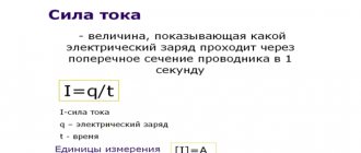
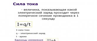
Electric current is characterized by current intensity. Current strength is the number of charged particles passing through the cross section of a conductor per unit time. The unit of measurement is Ampere.
Voltage – characterizes the potential difference between two points in an electric field. The unit of measurement is Volt.
Analogy with water.
What is electric current and what is voltage? To answer this question and fully understand, it is better to give an analogy. The analogy I want to give you has been given many times on the Internet; it is based on water. Since we deal with water every day, this analogy will be more understandable.
So, let's do an experiment. Let's take two vessels installed at the same level and connected by one hose.
Pour water into one vessel and leave the second empty. Water will begin to flow through the hose from the container with water into the empty container. The difference in levels in the vessels, in our analogy, is voltage, or potential difference.
The amount of water passing through the section of the hose per unit time will be the current strength.
If we change the hose to another one with a smaller internal diameter (or clamp the hose halfway) and repeat the experiment, we will see that water will flow from one vessel to another longer. You can use a stopwatch for this experiment. The internal diameter (section) of the hose in our analogy will be the resistance.
The smaller the diameter of the hose, the greater the resistance, and therefore the less current.
At the moment when the water levels in the vessels become equal (the potential difference is zero), the current strength becomes zero.
What other parameters does the current strength in a conductor depend on at a particular moment in time?
I in the circuit can be increased (theoretically) by changing a number of other parameters, such as:
- Resistance. The relationship between the parameters here is inversely proportional. Decreasing R (measured in Ohms) automatically increases the current.
- Voltage. If we consider the situation from the point of view of the practical operation of Ohm's law, it turns out that if the voltage is increased, the current strength will also increase.
These are the main parameters. In addition to them, the parameter under study is influenced by such factors as the magnetic field strength and the number of turns of the coil (direct dependence). A direct effect on the current value also occurs when the power of the force transmitted to the rotor changes.
It is also necessary to take into account the diameter of the conductors used in the assembled closed electrical circuit. If the size is insufficient, the risk of conductor overheating and, as a result, burnout increases. The main parameters of the generator are also taken into account (the magnitude of the operating current, the voltage and frequency range, and also the rotor rotation speed).
Increasing the current in a circuit: several possible options
Various categories of users quite often have situations in which it is necessary to make certain changes to the parameters of the current one. Previously assembled and tested network. It is possible to increase the strength of direct current flowing in a closed loop of a particular circuit; there are even several different options and methods of practical action. But it is important to understand that this can be done safely only if measures are taken to protect electrical appliances. To do this you will need to use a number of special devices.
1 way
The simplest solution to the problem is to increase the voltage supplied to the input of the circuit. So, for example, if a voltage of 3 volts is set in a circuit with a resistance of 20 Ohms, then the current here, according to Ohm’s law, is 0.15 A. If you introduce an additional device into the circuit, another power source with the same U = 3V, then and the current will double and be 3A.
Method 2
Reducing resistance. If we reduce the load in the circuit by half, from 2 Ohms to 1 Ohm, we get the following result: 2 V: 1 Ohm = 2 A. Thus, doubling occurs automatically by a similar amount (if there are no other sources, consumers and devices in the circuit that can influence the efficiency of the circuit and its parameters). Naturally, if you increase the resistance, the current will decrease.
3 way
We change the parameters of the conductors. To do this, you will need to assemble a circuit that will include: source, consumer and wires. The parameters of the conductors also play an important role in the formation of current strength in the circuit. First you need to understand what materials the original conductors are made of; using special tables, knowing the cross-sectional size, you can establish exact indicators. An increase in current can be achieved by reducing resistance, and for this you can select conductors made from other metals.
You can also adjust the parameters by shortening the length of existing conductors. If it is not possible to double the current, then in addition to changing the parameters of the conductors, you will need to make other decisions from those described above.
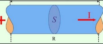
It is also possible to increase the cross-section of the conductor, which will lead to a parallel increase in current.
An interesting option for increasing the strength of direct current using a magnet, for which it is necessary to change and increase the magnetic induction of the field within which this conductor is located.
To main§ 16. Ohm's law
The relationship between e. d.s., resistance and current strength in a closed circuit is expressed by Ohm's law, which can be formulated as follows: the current strength in a closed circuit is directly proportional to the electromotive force and inversely proportional to the resistance of the entire circuit
. The current in the circuit flows under the influence of e. d.s.; the more e. d.s. source of energy, the greater the current in the closed circuit. The resistance of the circuit prevents the passage of current, therefore, the greater the resistance of the circuit, the less the current. With constant circuit resistance, the current strength in it is directly proportional to e. d.s. Ohm's law can be expressed by the following formula:
(22)
or
E = I
(
r
+
r
0), (23)
where r
— resistance of the external part of the circuit;
r
0 is the resistance of the internal part of the circuit.
To express small currents, milliamps ( mA
) are used instead of amperes;
1 a
= 1000
ma
. From formula (23) you can determine the resistance of the entire circuit:
If under the influence of e. d.s. If a current of one ampere flows in one volt in a closed circuit, then the resistance of such a circuit is equal to one ohm, i.e.
Ohm's law is valid not only for the entire circuit, but also for any section of it. We will mean a section of the circuit that does not contain an energy source. Within this region, positive charges move from points of higher potential to points of lower potential. The generator expends a certain amount of energy maintaining a potential difference between the beginning and end of this section. This potential difference is the voltage between the beginning and end of the section in question. Thus, applying Ohm’s law to a section of the chain, we replace e. in formulas (22) and (23). d.s. voltage between the beginning and end of this section U
, and the resistance of the entire circuit (
r
+
r
0) is the resistance of the section under consideration
r
. Consequently, for a section of an electrical circuit, the formula expressing Ohm’s law will take the following form:
In other words, Ohm's law can be formulated as follows: the current strength in a section of an electrical circuit is equal to the voltage between the ends of this section divided by its resistance
. From formula (24) it follows that
U = Ir
,
that is, the voltage in a section of the circuit is equal to the product of the current and the resistance of this section. Returning to formula (23) and opening the brackets, we get:
E = I r + I r
0, (25)
where I r
- voltage drop in resistance
r
, i.e. in the external part of the circuit, or, in other words, the voltage at the terminals of the energy source (generator)
U
;
ir
0 - voltage drop in resistance
r
0, i.e. inside the energy source (generator); it defines part of e. d.s., which is spent on passing current through the internal resistance of the energy source. We rewrite formula (25) in the following form:
E = U + I r
0. (26)
From formula (26) it follows that the voltage at the terminals of the energy source (generator) is equal to the difference between e. d.s. and the voltage drop in the internal resistance of this source:
U = E - Ir
, (27)
When idling, the external circuit is open and there is no current in the circuit, as a result of which the voltage at the terminals of the energy source is equal to its e. d.s. When the circuit is closed, the voltage is not equal to e. d.s., and the greater the current in the circuit, the more the voltage differs from e. d.s. If we reduce the external circuit resistance r
, then the resistance of the entire circuit
r
+
r
0 will also decrease, and the current strength in the circuit, as can be seen from formula (22), will increase.
As the current increases, the voltage drop inside the energy source ( I r
0) will increase, since the internal resistance
r
0 of the energy source remains unchanged. Consequently, from formula (27) it follows that with a decrease in the resistance of the external circuit, the voltage at the terminals of the energy source also decreases. If the terminals of the energy source are connected with a conductor with a resistance almost equal to zero, then formula (22) for this case will take the following form:
This expression determines the maximum current that can be obtained in the circuit of a given source. If the resistance of the external circuit is practically zero, then this mode is called a short circuit
source of energy.
For energy sources with low internal resistance, for example, for electric generators (electric machines) and acid batteries, a short circuit is very dangerous - it can destroy these sources. So, for example, a battery of acid batteries (type C-1) with e. d.s. 220 V
has an internal resistance of 0.5
ohm
. When such a battery is short-circuited, the current is
Since for the given type of battery with a normal (ten-hour) discharge the current is 3.6 A
, then a current of 440
A
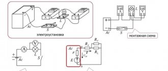
is certainly dangerous for the integrity of the battery. A short circuit occurs relatively often, for example due to damage to the insulation of the wires connecting the receiver to the power source. Without an insulating cover, metal (usually copper or aluminum) linear wires, when in mutual contact, form a very small resistance, which, compared to the resistance of the receiver, can be taken equal to zero. To protect electrical equipment from short circuit currents, various safety devices are used. To measure the current in a circuit, a device called an ammeter (milliammeter) is used. Voltage, as mentioned above, is measured with a voltmeter. The symbol for ammeter and voltmeter is shown in Fig. 15, a.
To turn on the ammeter, the current circuit is broken and at the break point the ends of the wires are connected to the ammeter terminals (Fig. 15, b). Thus, the entire measured current passes through the device; such inclusion is called sequential
.
The voltmeter is connected to the beginning and end of the circuit section; This connection of the voltmeter is called parallel
.
The voltmeter shows the voltage drop in a given area. If a voltmeter is connected to the beginning of the external circuit - the positive pole of the energy source and to the end of the external circuit - the negative pole of the energy source, then it will show the voltage drop in the entire external circuit, which is at the same time the voltage at the terminals of the energy source. Previous page
| table of contents | Next page |
