The author of the article is a professional tutor, author of textbooks for preparing for the Unified State Exam Igor Vyacheslavovich Yakovlev
Topics of the Unified State Examination codifier: electromotive force, internal resistance of a current source, Ohm's law for a complete electrical circuit.
Until now, when studying electric current, we have considered the directional movement of free charges in an external circuit
, that is, in the conductors connected to the terminals of the current source.
As we know, positive charge:
• goes into the external circuit from the positive terminal of the source;
• moves in an external circuit under the influence of a stationary electric field created by other moving charges;
• comes to the negative terminal of the source, completing its path in the external circuit.
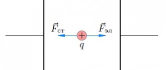
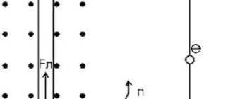
Now our positive charge needs to close its path and return to the positive terminal. To do this, he needs to overcome the final segment of the path - inside the current source from the negative terminal to the positive. But think about it: he doesn’t want to go there at all! The negative terminal attracts it towards itself, the positive terminal repels it from itself, and as a result, our charge inside the source is acted upon by an electric force directed against
movement of the charge (i.e. against the direction of the current).
What is EMF: explanation in simple words
EMF is understood as the specific work of external forces to move a single charge in the circuit of an electrical circuit. This concept in electricity involves many physical interpretations related to various areas of technical knowledge. In electrical engineering, this is the specific work of external forces that appears in inductive windings when an alternating field is induced in them. In chemistry, it means the potential difference that occurs during electrolysis, as well as during reactions accompanied by the separation of electrical charges.
What is a photoresistor?
Read more
Marking of SMD transistors.
Read more
How to make a motion sensor with your own hands.
Read more
In physics, it corresponds to the electromotive force created at the ends of an electrical thermocouple, for example. To explain the essence of EMF in simple words, you will need to consider each of the options for its interpretation. Before moving on to the main part of the article, we note that EMF and voltage are very similar concepts in meaning, but they are still somewhat different. In short, the EMF is on the power source without a load, and when a load is connected to it, it is already a voltage. Because the number of volts on the power supply under load is almost always slightly less than without it. This is due to the internal resistance of power sources such as transformers and galvanic cells.
Additional material on the topic: In simple words about voltage converters.
Electromotive force (emf), a physical quantity characterizing the action of third-party (non-potential) forces in direct or alternating current sources; in a closed conducting circuit is equal to the work of these forces to move a single positive charge along the circuit. If we denote the field strength of external forces by Etr, then the emf in a closed loop (L) is equal to , where dl is the element of the loop length. The potential forces of an electrostatic (or stationary) field cannot maintain a constant current in the circuit, since the work of these forces on a closed path is zero. The passage of current through the conductors is accompanied by the release of energy - heating of the conductors.
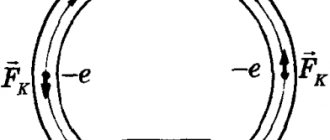
Third-party forces set in motion charged particles inside current sources: generators, galvanic cells, batteries, etc. The origin of third-party forces can be different. In generators, external forces are forces from the vortex electric field that arises when the magnetic field changes over time, or the Lorentz force acting from the magnetic field on electrons in a moving conductor; in galvanic cells and batteries - these are chemical forces, etc. Emf determines the current strength in the circuit at a given resistance (see Ohm's law). EMF, like voltage, is measured in volts.
What is EMF.
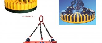
Interaction of a magnet with a circuit
So, the approach or removal of a magnet leads to the appearance of an induced current in the circuit, the direction of which is determined by Lenz’s rule. But the magnetic field acts on the current! An Ampere force will appear acting on the circuit from the magnetic field. Where will this force be directed?
If you want to have a good understanding of Lenz's rule and the determination of the direction of the Ampere force, try answering this question yourself. This is not a very simple exercise and an excellent task for C1 on the Unified State Exam. Consider four possible cases.
1. We bring the magnet closer to the circuit, the north pole is directed towards the circuit. 2. We remove the magnet from the circuit, the north pole is directed towards the circuit. 3. We bring the magnet closer to the circuit, the south pole is directed towards the circuit. 4. We remove the magnet from the circuit, the south pole is directed towards the circuit.
Do not forget that the magnetic field is not uniform: the field lines diverge from the north pole and converge towards the south. This is very important for determining the resulting Ampere force. The result is as follows.
If you bring the magnet closer, the circuit is repelled from the magnet. If you remove the magnet, the circuit is attracted to the magnet. Thus, if the circuit is suspended on a thread, then it will always deviate in the direction of the movement of the magnet, as if following it. The location of the magnet poles does not matter in this case.
.
In any case, you should remember this fact - what if such a question comes up in part A1
This result can be explained from completely general considerations - using the law of conservation of energy.
Let's say we bring the magnet closer to the circuit. An induction current appears in the circuit. But to create a current, work must be done! Who does it? Ultimately, we are, moving the magnet. We perform positive mechanical work, which is converted into positive work of external forces arising in the circuit, creating an induced current.
So our work to move the magnet should be positive
.
This means that when we bring the magnet closer, we must overcome
the force of interaction between the magnet and the circuit, which, therefore, is a
repulsive
.
Now remove the magnet. Please repeat these arguments and make sure that an attractive force should arise between the magnet and the circuit.
Nature of EMF
The reason for the occurrence of EMF in different current sources is different. Based on the nature of occurrence, the following types are distinguished:
- Chemical emf. Occurs in batteries and accumulators due to chemical reactions.
- Thermo EMF. Occurs when contacts of dissimilar conductors located at different temperatures are connected.
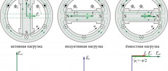
- Induction emf. Occurs in a generator when a rotating conductor is placed in a magnetic field. An emf will be induced in a conductor when the conductor crosses the lines of force of a constant magnetic field or when the magnetic field changes in magnitude.
- Photoelectric emf. The occurrence of this EMF is facilitated by the phenomenon of external or internal photoelectric effect.
- Piezoelectric emf. EMF occurs when substances are stretched or compressed.
It will be interesting➡ What is electrical resistance
Electromagnetic induction (self-induction)
Let's start with electromagnetic induction. This phenomenon is described by Faraday's law of electromagnetic induction. The physical meaning of this phenomenon is the ability of an electromagnetic field to induce an emf in a nearby conductor. In this case, either the field must change, for example, in the magnitude and direction of the vectors, or move relative to the conductor, or the conductor must move relative to this field. In this case, a potential difference arises at the ends of the conductor.
Experience demonstrates the appearance of EMF in a coil when exposed to a changing magnetic field of a permanent magnet. There is another phenomenon that is similar in meaning - mutual induction. It lies in the fact that a change in the direction and current strength of one coil induces an EMF at the terminals of a nearby coil; it is widely used in various fields of technology, including electrical and electronics. It underlies the operation of transformers, where the magnetic flux of one winding induces current and voltage in the second.
What is self-induction.
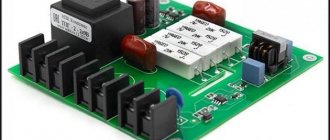
In electrical engineering, a physical effect called EMF is used in the manufacture of special AC converters that provide the required values of effective quantities (current and voltage). Thanks to the phenomena of induction and self-induction, engineers have been able to develop many electrical devices: from a conventional inductor (inductor) to a transformer. The concept of mutual induction refers only to alternating current, the flow of which in a circuit or conductor changes the magnetic flux.
Table of parameters of electromotive force of induction.
Magnetic flux
Magnetic flux through the area \( S \) of the contour is called a scalar physical quantity equal to the product of the magnitude of the magnetic induction vector \( B \), the surface area \( S \), penetrated by this flux, and the cosine of the angle \ ( \alpha \) between the direction of the magnetic induction vector and the normal vector (perpendicular to the plane of a given surface):
The designation is \( \Phi \), the SI unit is weber (Wb).
A magnetic flux of 1 weber is created by a uniform magnetic field with an induction of 1 T through a surface of 1 m2 located perpendicular to the magnetic induction vector:
Magnetic flux can be visualized as a value proportional to the number of magnetic lines passing through a given area.
Depending on the angle \( \alpha \) the magnetic flux can be positive (\( \alpha \) < 90°) or negative (\( \alpha \) > 90°). If \( \alpha \) = 90°, then the magnetic flux is 0.
You can change the magnetic flux by changing the area of the circuit, the field induction module, or the location of the circuit in the magnetic field (by rotating it).
In the case of a non-uniform magnetic field and a non-flat contour, the magnetic flux is found as the sum of the magnetic fluxes penetrating the area of each of the sections into which a given surface can be divided.
EMF in everyday life and units of measurement
Other examples are found in the practical life of any ordinary person. This category includes such familiar things as small batteries, as well as other miniature batteries. In this case, the working EMF is formed due to chemical processes occurring inside constant voltage sources. When it occurs at the terminals (poles) of the battery due to internal changes, the element is completely ready for operation. Over time, the EMF decreases slightly, and the internal resistance increases noticeably.
As a result, if you measure the voltage on a AA battery that is not connected to anything, you see the normal 1.5V (or so), but when a load is connected to the battery, let’s say you installed it in some device, it does not work. Why? Because if we assume that the voltmeter’s internal resistance is many times higher than the internal resistance of the battery, then you measured its EMF. When the battery began to supply current to the load at its terminals, it became not 1.5V, but, say, 1.2V - the device did not have enough voltage or current for normal operation.
Calculation of EMF.
It was precisely these 0.3 V that dropped on the internal resistance of the galvanic element. If the battery is very old and its electrodes are destroyed, then there may be no electromotive force or voltage at all at the battery terminals - i.e. zero. A very small electromotive force is induced within the receiver antenna, which is then amplified by special cascades, and we receive our television, radio and even Wi-Fi signal.
Material on the topic: Selecting a digital-to-analog converter.
Introduction.
Inductor back emf is a difficult topic to understand due to the effects that occur around the current carrying coil.
impossible to see directly.
This gives rise to a lot of speculation that has little to do with reality. And since phenomena and effects are recorded only by objective methods using special instruments, people begin to judge them on the basis of their similarity
with some other phenomena, with which people are well familiar from life experience.
For example, the model of an electron rotating around an atomic nucleus is similar to a rotating ball tied to a string
.
This method of establishing the similarity of one phenomenon to another is
called a physical model.
This method was used by all outstanding physicists of the 20th century. For example, the Bohr atom model was built similar to
the functioning of the solar system, and an airplane,
like
a bird, has wings, a tail, plumage, etc., which were also borrowed from nature, which remained in the very names of the parts of the airplane. The examples given are enough, only one thing remains to be added: no matter what complex and intricate phenomena in physics we take, all of them, without exception, are similar to something simple, known to people from experience or in everyday life, and always represent a physical model.
The method of cognition from the particular to the general is always carried out on the basis of establishing similarity
and represents
a movement from bottom to top
.
There is another way of knowing from the general to the specific, that is, by analogy
and represents
a movement from top to bottom.
But people are still more occupied with their animal nature and know little about this method, so they rarely use it. Full cognition is based on the dynamic balance of these two methods. But in their lives, unfortunately, most people are still very far from the concepts of dynamic balance, harmony, equilibrium, balance.
How is EMF formed?
The ideal source of EMF is a generator whose internal resistance is zero and the voltage at its terminals does not depend on the load. The power of an ideal EMF source is infinite. A real EMF source, unlike an ideal one, contains an internal resistance Ri and its voltage depends on the load (Fig. 1, b), and the power of the source is finite. The electrical circuit of a real EMF generator is a series connection of an ideal EMF generator E and its internal resistance Ri.
It will be interesting➡ What is inductance
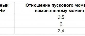
In practice, in order to bring the operating mode of a real EMF generator closer to the operating mode of an ideal one, they try to make the internal resistance of the real generator Ri as small as possible, and the load resistance Rн must be connected with a value no less than 10 times greater than the internal resistance of the generator, i.e. it is necessary to fulfill the condition: Rн >> Ri
To ensure that the output voltage of a real EMF generator does not depend on the load, it is stabilized using special electronic voltage stabilization circuits. Since the internal resistance of a real EMF generator cannot be made infinitely small, it is minimized and made standard for the possibility of coordinated connection of energy consumers to it. In radio engineering, the standard output resistance of EMF generators is 50 Ohms (industrial standard) and 75 Ohms (household standard).
For example, all television receivers have an input impedance of 75 Ohms and are connected to the antennas with a coaxial cable of exactly this impedance. To get closer to ideal EMF generators, supply voltage sources used in all industrial and household electronic equipment are made using special electronic output voltage stabilization circuits, which make it possible to maintain an almost constant output voltage of the power source in a given range of currents consumed from the EMF source (sometimes its called a voltage source).
On electrical diagrams, EMF sources are depicted as follows: E - source of constant EMF, e(t) - source of harmonic (variable) EMF in the form of a function of time. The electromotive force E of a battery of identical elements connected in series is equal to the electromotive force of one element E multiplied by the number n of elements of the battery: E = nE.
Direct current and EMF.
Electromotive force (EMF) of the energy source
To maintain an electric current in a conductor, an external energy source is required, which constantly creates a potential difference between the ends of this conductor. Such energy sources are called electrical energy sources (or current sources). Sources of electrical energy have a certain electromotive force (abbreviated EMF), which creates and maintains a potential difference between the ends of the conductor for a long time.
Expert commentary
Lagutin Vitaly Sergeevich
Engineer with a degree in Computer Software and Automated Systems, MEPhI, 2005–2010.
Ask a Question
It is sometimes said that emf creates an electric current in a circuit. We must remember that this definition is conventional, since we have already established above that the reason for the emergence and existence of electric current is the electric field.
A source of electrical energy produces a certain amount of work by moving electrical charges throughout a closed circuit. The unit of measurement of electromotive force is the volt (abbreviated volt is denoted by the letter B or V - “ve” in Latin). The emf of a source of electrical energy is equal to one volt if, when moving one coulomb of electricity throughout a closed circuit, the source of electrical energy does work equal to one joule:
Electromotive force (EMF) of an energy source.
In practice, both larger and smaller units are used to measure EMF, namely:
- 1 kilovolt (kV, kV), equal to 1000 V;
- 1 millivolt (mV, mV), equal to one thousandth of a volt (10-3 V),
- 1 microvolt (μV, μV), equal to one millionth of a volt (10-6 V).
Obviously, 1 kV = 1000 V; 1 V = 1000 mV = 1,000,000 μV; 1 mV = 1000 µV.
Currently, there are several types of electrical energy sources. For the first time, a galvanic battery was used as a source of electrical energy, consisting of several zinc and copper circles, between which skin soaked in acidified water was laid. In a galvanic battery, chemical energy was converted into electrical energy (this will be discussed in more detail in Chapter XVI). The galvanic battery got its name from the Italian physiologist Luigi Galvani (1737-1798), one of the founders of the doctrine of electricity.
Numerous experiments on the improvement and practical use of galvanic batteries were carried out by the Russian scientist Vasily Vladimirovich Petrov. At the beginning of the last century, he created the world's largest galvanic battery and used it for a number of brilliant experiments. Sources of electrical energy that work on the principle of converting chemical energy into electrical energy are called chemical sources of electrical energy.
Good to know: How to calculate the power of an electric current.
Another main source of electrical energy, widely used in electrical and radio engineering, is the generator. In generators, mechanical energy is converted into electrical energy. In chemical sources of electrical energy and in generators, the electromotive force manifests itself in the same way, creating a potential difference at the source terminals and maintaining it for a long time.
These terminals are called the poles of the electrical energy source. One pole of an electrical energy source has a positive potential (lack of electrons), is indicated by a plus sign (+) and is called the positive pole.
The other pole has a negative potential (excess electrons), is indicated by a minus sign (—) and is called the negative pole. From sources of electrical energy, electrical energy is transmitted through wires to its consumers (electric lamps, electric motors, electric arcs, electric heating devices, etc.).
It will be interesting➡ Joule Lenz's Law - the most complete theory
Examples of problem solving
For each position in the first column, select the corresponding position in the second:
| PHYSICAL QUANTITIES | FORMULAS |
| Electromotive force | |
| Current strength | |
| Resistance | |
| Potential difference |
Solution: The electromotive force of a galvanic cell is a quantity numerically equal to the work of external forces when moving a single positive charge inside the element from one pole to the other.
The work of external forces cannot be expressed through a potential difference, since external forces are non-potential and their work depends on the shape of the trajectory of the charges.
EMF is determined by the formula:
The current strength is determined by the formula:
Resistance is determined by the formula:
The potential difference is determined by the formula:
Correct answer:
| PHYSICAL QUANTITIES | FORMULAS |
| Electromotive force | |
| Current strength | |
| Resistance | |
| Potential difference |
FAQ
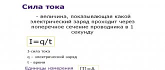
What is electromotive force?
This is the ratio of the work of external forces when moving a charge along a closed circuit to the absolute value of this charge.
What is an electrical circuit?
A set of devices that are connected by conductors, designed to allow current to flow.
What does Ohm's law sound like for a complete circuit?
The current strength in a complete circuit is equal to the ratio of the circuit's emf to its total resistance.