At first I smelled a burning smell, and when after a short time only the maximum fan speed remained, it became clear that something was damaged.
It would seem - just replace the resistor and you're done. But a review of prices on the Internet and offers with used resistors revealed an average price of 1000 rubles, and I won’t even write the cost of new ones! But is it worth buying used? Therefore, the question arises how long such a resistor will last. So the idea came up to make an electronic version of it. But first you must answer the question, why did the resistor burn out in the first place? It is advisable to eliminate the cause, and not just the consequences of the failure. Of course, you can install even stronger elements. But most often the reason for the resistor burning lies in the bearings of the fan motor. Increasing the resistance at the bearings causes the resistor to heat up more and therefore trip the fuse. When replacing a resistor, it is recommended to lubricate the bearings; it is best to disassemble the fan and check, clean, lubricate or replace the bearings inside the electric motor. Once I changed the resistor three times in a Citroen Berlingo, but a drop of lubricant was enough to stop the resistors from burning anymore.
Another common cause of a resistor (but more often a fuse) burning out is a clogged cabin filter. This reduces airflow and reduces cooling of the fan resistors. Dirt on the filter also causes moisture accumulation and corrosion of resistors - you need to change the cabin filter regularly.
Digital and mechanical potentiometers: differences
The “evolution” of resistors does not stand still. Therefore, it is increasingly rare to find mechanical versions of radio elements in various types of equipment, from amateur radio to devices with LCD displays. They were replaced by digital potentiometers.
Although users note that the functionality of conventional resistors and CPUs is comparable, in terms of technical parameters and reliability, the latter have much higher potential.
CPU and PR are interchangeable resistors with wide resistance ranges. But they also have differences:
- Mechanical potentiometers can withstand large voltage loads and successfully dissipate power. But over time they wear out, and their technical performance deteriorates. Such changes are associated with the design feature of the PR. This does not threaten digital analogues, since they do not have mechanical parts that are the first to wear out, become loose or change shape.
- Mechanical resistors are very sensitive to shocks and shocks, and their moving element can oxidize over time, which also affects their service life. The CPU is made up of multiple IC switches (CMOS), making it resistant to various impacts such as shock, environmental changes, wear and tear, and more.
So it makes sense that all kinds of modern electronic devices have digital potentiometers built into them.
Design Theory - Analysis IV
Current-voltage (IV) characteristics determine how a field-effect transistor VCR will operate. In particular, the linear sections of the I-V characteristic determine the range of the input signal in which the VCR will behave as a resistor. The curves of a particular JFET also determine the range of resistor values that the VCR can be programmed to.
The mathematical function that defines the IV curve of a JFET is not linear. However, there are parts of these curves that are very linear. These include the triode region (also known as the ohmic or linear region) and the saturation region (also known as the active or DC source region). In the triode region, the JFET acts as a resistor, but in the saturation region it behaves as a constant current source. The point separating the triode region and the saturation region is approximately equal to the point where V
DS is equal to
V
GS on each of the current-voltage characteristics.
In the triode region, changes in drain-source voltage will not change (or change very little) the resistance between the drain and source terminals of the FET. In the saturation region, or more precisely in the constant current region, changes in the drain-source voltage will require changes in the drain-source resistance such that the current remains at a constant value for different drains. voltage levels.
For V
GS near zero, the drain-source voltage linearization or break point of the triode is much higher than when
V
GS levels are close to the cutoff voltage.
This means that to maintain constant resistor behavior for different VGS
, the maximum linearization value will be set according to the largest
VGS
used.
The linear triode region actually includes negative V
G.S.
The figure below shows an LTSPICE I-V simulation in the triode region. As can be seen, the nonlinear LSK489 is approximately linear from -0.1 V to 0.1 V. V
GS levels around 0 V, the linear range of the triode extends from -0.2 V to 0.2 V. As the value of
V
GS increases, the region linear triode is significantly reduced.
Conversely, when linearization resistors are used, a similar I-V sweep simulation shows that the linear triode region is significantly expanded. It is clear from the current-voltage characteristic that the linearization region for a linearized design easily expands from -6 V to 6 V ( i
DS vs
V
DS vs
V
in curves). Well above the approximately 200 mV range produced by the nonlinear design.
Also interesting is the fact that linearization results in linearization of the gate-source voltage, even if the input voltage ( V
c) is maintained at a constant DC level during each sweep.
This is because when the input voltage changes, the value of V
GS changes the voltage so that
V
GS is always equal to half of
V
DS.
The change in V
GS for changes in
V
DS is such that the JFET behaves like a resistor until the JFET saturates.
What to consider when choosing a CPU
If you need to buy a digital potentiometer, you should know what parameters to pay attention to. Among them:
- Input signal level (voltage).
- Maximum power and current.
- Impedance (a measure of total resistance).
- Resolution level.
- Number of channels.
- Linearity of resistance.
- Power-on position.
- The presence or absence of volatile memory.
- Resistor interface.
- Device size.
Preference should be given to the CPU whose parameters are most suitable for a specific task. For example, the latter indicator is extremely important for applications and circuits that are critically limited in size. Although some users note that it is possible to make such a potentiometer with your own hands, such work is not worth the time and effort. There is such a large selection of CPUs on sale, and at an affordable price, that you can choose one for any purpose and device.
Symbols on diagrams
On diagrams in Europe and the CIS it is indicated by a rectangle and a Latin letter R. According to GOST, on domestic diagrams the resistance rating is not indicated, but only the part number (R). However, if there is a number below the part image, such as 120, it will default to read 120 ohms.
The table contains examples of part designations.
| Basic designation |
| 0.125 W |
| 0.25 W |
| 0.5 W |
| 1 W |
| 2 W |
| 5 W |
| Variable |
| Trimmer |
Main CPU parameters
The most important indicator of this type of resistor is the number of steps, that is, switched taps. It is most often referred to as a power of 2. The most common CPUs are from 32 to 256 steps.
Also, when choosing a device, impedance is considered an important parameter. On sale you can most often find resistors with values of 10 kOhm, 50 kOhm and 100 kOhm.
You also need to pay attention to the maximum voltage at the terminals in the extreme position, look at the level of permissible current, nonlinearity, temperature coefficient and power dissipation.
Device performance may vary between different manufacturers, so it is better to select based on the needs of the equipment for which they are used. Below is a table with the parameters, characteristics and features of potentiometers.
Microcircuits MCP41XXX/MCP42XXX Microschip is an electronic variable resistor controlled by serial data via an SPI interface. It may have 1 or 2 channels and additional inputs for reset, shutdown, as well as a digital output for cascading such devices into a chain according to control data (the number of channels and the presence of additional pins depends on the type of device case).
Note: here is a translation of the datasheet [1] with an emphasis on programming and application. For tables with electrical parameters, maximum permissible parameters and timing diagram parameters, see the original datasheet.
[Basic features of a digital potentiometer]
• Each potentiometer channel has 256 “slider” positions. • Resistance values can be 10 kΩ, 50 kΩ and 100 kΩ. • There are single-channel and dual-channel versions of the chip. • SPI serial interface (0.0 and 1.1 modes). • Integral nonlinearity (INL) differential nonlinearity (DNL) are ±1 weight of the least significant bit (LSB). • Low power CMOS technology is used, in static mode the current consumption is a maximum of 1 μA. • Several microcircuits can be connected into one cascading chain for data transmission. • One supply voltage (2.7 .. 5.5V). • Industrial version for temperature range: -40° .. +85°C. • Extended temperature range: -40° .. +125°C. • Shutdown function opens circuits to all resistors for maximum power saving.
Only for dual channel versions of MCP42XXX:
• Hardware ~SHDN shutdown, ~RS reset, and SO data output pins.
The MCP41XXX versions are single-channel devices supplied in 8-pin PDIP or SOIC packages. MCP42XXX versions contain 2 independent channels in 14-pin PDIP, SOIC or TSSOP packages. The position of the “engine” of the MCP41XXX/42XXX resistors changes according to a linear law and under the control of a standard SPI interface. The shutdown function, activated by software, works in such a way that the A pin of the variable resistor is turned off, and at the same time the “switch” W is connected to the B pin. Additionally, two-channel versions of the MCP42XXX electronic potentiometer have an ~SHDN pin, which performs the same function, but in hardware . During shutdown mode, the contents of the slider position register can be changed, causing the potentiometer to return from shutdown to the new slider position.
The motor resets to the middle position 80h after turning on the power. The ~RS pin (reset, available only in dual-channel versions of the MCP42XXX) implements a hardware reset, returning the resistor slider to the middle position.
The SPI interface of MCP42XXX microcircuits has 2 signals SI and SO (input and output), allowing several devices to be cascaded in series.
The resistances of the MCP42XXX channels differ by no more than 1%.
Pinout of PDIP8, SOIC8 cases:
Pinout of PDIP14, SOIC14, TSSOP14 housings:
[Description of pins]
| PB0, PB1 | Potentiometer terminal B. A variable resistor terminal that is normally connected to ground when in use. |
| PA0, PA1 | Potentiometer terminal A. A variable resistor terminal that typically receives an adjustable signal. |
| PW0, PW1 | "Engine" potentiometer/variable resistor. |
| ~CS | This is the SPI port select input pin (chip select) which is used to load command and data into the shift register and copy the loaded data in from the shift register to the potentiometer register(s). The signal from this pin passes through a Schmitt trigger. |
| SCK | This is the clock input pin of the SPI port and is used to serially load commands and data into the chip. Data is pushed into the SI pin by the positive edge of SCK (0 -> 1), and out through the SO pin by the negative edge of SCK (1 -> 0). This pin is activated by the ~CS pin (for example, the chip consumes almost no current if the SCK pin is switched when the ~CS pin is at logic 1). The signal from the SCK pin passes through the Schmitt trigger. |
| S.I. | This is the serial data input of the SPI port. The command and data bytes are pushed into the shift register through this pin. The action of the SI input is controlled by the ~CS pin (the chip does not consume current and does not respond to input data when it changes at the SI pin if the ~CS pin is at logic 1). The signal to the SI pin passes through a Schmitt trigger. |
| SO | This is the serial data output of the SPI port, designed to connect multiple chips in a chain. Data is pushed out through the SO pin on the falling edge of the SCK clock signal. The SO output is push-pull, and it does not go into the third state when the ~CS input is log. 1. If at ~CS log. 1, then the SO output will be log. 0. |
| ~RS | This is a reset input, which moves the state of the potentiometers to the middle position (code 80h) if a log appears on this pin. 0 for at least 150 ns. This output is not switched to the log. 0 when ~CS switches to log. 0. You can switch the reset input when ~SHDN is in log. 0. To reduce current consumption, the reset input must be pulled up to log. 1 through a pull-up resistor. The performance of this scheme is shown in Fig. 2-12 datasheet [1]. This pin will draw unwanted current when at a level between log. 0 and log. 1, so don't leave the reset input hanging. |
| ~SHDN | This is a hardware shutdown input equipped with a Schmitt trigger. If we translate this output into log. 0, then the microcircuit will go into energy-saving mode, in which pin A of the variable resistors is turned off, and pins B and W are connected to each other. The ~SHDN input should not go to the log. 0 when the ~CS pin is in the log. 0. To minimize power consumption, this pin should have a top pull-up resistor. The performance of this scheme is shown in Fig. 2-12 datasheet [1]. This pin will draw unwanted current when at a level between log. 0 and log. 1, so don't leave the reset input hanging. |
| VSS | GND, ground, power supply and common for all digital signals. |
| VDD | + food. |
[4.0. Application information ]
The MCP41XXX/MCP42XXX devices are single and dual channel potentiometers with 256 positions that can be used in place of conventional mechanical potentiometers. Available in 10 kOhm, 50 kOhm and 100 kOhm ratings. As shown in Fig. 4-1, each potentiometer is built from an array of switched resistors, controlled by an 8-bit (hence 256 positions) data register that determines the position of the "switch". The nominal resistance of the motor is 52 ohms for the 10 kohm version, 125 ohms for the 50 kohm version and 100 kohm version. For two-channel devices, the difference in resistance between channels is no more than 1%. The resistance between the motor and either end of the resistor varies linearly depending on the value stored in the data register. Code 00h connects the W slider to the B pin. After turning on the power, all data registers are automatically loaded with the average value (80h). The serial interface provides a way to load data into a shift register and then move it into the data registers. The serial interface also allows individual potentiometers to be put into shutdown mode to minimize power consumption. The ~SHDN pin can also be used to set all potentiometers to shutdown mode (shutdown mode can be set individually for each potentiometer in software), and the ~RS pin is provided to set the potentiometers to the mid-scale (80h) position.
Shutdown turns off pin A and connects engine W to pin B, without changing the state of the data registers.
When wiring a PCB using digital potentiometers, blocking capacitors must be used. They should be connected as close as possible to the power pins of the microcircuit. It is recommended to use a 0.1 µF capacitor. Digital and analog conductors should be as far apart from each other on the board as possible; it is advisable that there are no conductors under the chip body or under the capacitor body. Particular attention must be paid to conductors carrying high-frequency signals (such as clock signals), so that they are kept as far away from conductors as possible from analog signals. Using an analog fill is recommended to keep the ground potential the same for all devices on the board.
4.1. Operating modes . Digital potentiometer applications can be divided into 2 categories: rheostat and potentiometer mode, or voltage divider mode.
4.1.1. Rheostat mode . In this mode, the potentiometer is used as a two-terminal resistive element (variable resistor). The unused pin must be connected to the motor as shown in Fig. 4-2. Please note that changing the polarity of pins A and B does not affect the operation of the potentiometer in rheostat mode (changing the polarity will simply change the effect of the recorded codes).
Rice. 4-2. Rheostat configuration with two terminals. It works in the circuit as a variable resistive element, the resistance of which changes under the control of a digital code.
Using the device in this mode allows you to change the total resistance between two circuit nodes. The total resistance measured will be minimum for code 00h when the W slider is connected to pin A and has moved to pin B. The resistance will be equal to the slider resistance, which will be typically 52Ω for 10 kΩ MCP4X010 devices, 125Ω for 50 kΩ (MCP4X050) and 100 kΩ (MCP4X100) devices. For a 10 kΩ device, the weight of the least significant digit of regulation is 39.0625Ω (assuming a total resistance of 10 kΩ). The resistance will increase as the code increases, and will be maximum 9985.94Ω for the FFh code. The motor will never be directly connected to point B of the resistor stack.
In state 00h, the total resistance will be equal to the resistance of the motor W. To avoid damage to the microcircuit, you should limit the current through the variable digital resistor to 1 mA.
For two-channel devices, the difference in resistance between points A and B between channels will be less than 1%. However, between different microcircuits the discrepancy can be up to 30%.
In rheostat mode, the resistance has a positive temperature coefficient. The change in resistance between the motor and the outer terminal depending on temperature is shown in Fig. 2-8 datasheets [1]. The largest change due to temperature will occur for 6% of codes (in the range 00h .. 0Fh) due to the fact that the resistance coefficient of the engine affects the overall resistance. For the remaining codes, the dominant contribution will be the temperature coefficient of the RAB resistor array, which is typically 800 ppm/°C.
4.1.2. Potentiometer mode . In potentiometer mode, all 3 pins of the device are connected to different points in the circuit. This allows you to change the voltage on the engine (output) in proportion to the code. This mode is sometimes called voltage divider mode. A potentiometer is used to provide an adjustable voltage between two points, as shown in Fig. 4-3. Please note that changing the polarity of pins A and B does not affect operation (changing the polarity will simply change the effect of the codes being written).
Rice. 4-3. Voltage divider (potentiometer) mode.
In this configuration, the internal resistance ratio is determined by the temperature coefficient of the device. The temperature coefficient agreement between RAB and RWB is 1 ppm/°C (measured for code 80h). For codes with lower values, the temperature coefficient of the engine will dominate. Rice. Datasheet 2-3 [1] shows the effect of the engine temperature coefficient. Above the lower codes, this figure shows that 70% of states will give a temperature coefficient of less than 5 ppm/°C. 30% of conditions will give ppm/°C less than 1.
4.2. Typical Applications
4.2.1. Programmable amplifiers with single-ended output . Potentiometers are often used to adjust reference voltage or gain levels. Programmable gain circuits based on digital potentiometers can be implemented in a variety of ways. An example of an inverting amplifier with a single power supply is shown in Fig. 4-4. Due to the high input impedance of the amplifier, the motor resistance does not participate in the transfer function.
VOUT = -VIN * (RB/RA) + VREF * (1 + RB/RA) Here: RAB*(256 – Dn) RAB * Dn RA = ————— RB = ——— 256 256 RAB = total resistance channel Dn = engine setting (Dn = 0 .. 255)
Rice. 4-4. Single-supply inverting programmable amplifier.
For a non-inverting amplifier with single-pole power supply, the circuit in Fig. 4-5.
VOUT = VIN * (1 + RB/RA) Here: RAB*(256 – Dn) RAB * Dn RA = ————— RB = ——— 256 256 RAB = total channel resistance Dn = engine setting (Dn = 0 .. 255)
Rice. 4-5. Single-supply non-inverting programmable amplifier.
In order for these schemes to work correctly, some points must be taken into account. For linear operation, the input and output signals must not go beyond the levels of the VSS and VDD pins of the potentiometer chip and must not exceed the input and output signal limits of the op-amp. Scheme in Fig. 4-4 requires a virtual ground or voltage reference for a non-inverting amplifier. For more information, see Note 682, Using Single-Supply Operational Amplifiers in Embedded Systems (DS00682). When the power is turned on or a reset signal (~RS) is received, the resistance will be set to the middle position when the resistance of the RA and RB arms are equal. Based on the transfer function of the circuit, the gain will be 1. As the code increases, the slider moves towards pin A and the gain increases. Accordingly, when the slider moves to pin B, the gain decreases. Rice. 4-6 shows this dependence. Note the pseudo-logarithmic gain around decimal code 128. As the engine gets closer to any of the pins, the slope of the gain change increases sharply. Due to the discrepancy between the values of RA and RB for the extreme high and low codes, a small change in the position of the engine has a very strong effect on the gains. As shown in Fig. 4-3, it is recommended to use gain variation in the range from 0.1 to 10.
Rice. 4-6. Dependence of gain on code for inverting and differential amplifier circuits.
4.2.2. Programmable differential amplifier . An example of a differential input amplifier using digital potentiometers is shown in Fig. 4-7. To support the transfer function, both resistor channels must be programmed with the same code. The exact resistance match between the channels of the dual resistor can be used as an advantage for this circuit. This circuit will also show stable operation over temperature due to the low temperature coefficient of the potentiometer. In Fig. Figure 4-6 also shows the relationship between gain and code for this circuit. When the slider approaches any of the potentiometer pins, the gain changes very significantly with each new step, so it is recommended to change the gain in the range between 0.1 and 10.
VOUT = (VA - VB) * RB/RA Here: RAB*(256 – Dn) RAB * Dn RA = ————— RB = ——— 256 256 RAB = total channel resistance Dn = engine setting (Dn = 0 .. 255) Note: the resistances of the RAB channels must be the same (channels from the same MCP42XXX housing).
Rice. 4-7. Single-supply differential amplifier.
4.2.3. Programmable offset adjustment . For applications where only a programmable reference voltage is required, the circuit in Fig. 4-8. This circuit shows the device used in potentiometer (voltage divider) mode with two additional resistors and a buffer amplifier. This creates a linear relationship between the output voltage and the programmable code. Resistors R1 and R2 can be used to decrease or increase the weight of the control step. The potentiometer in this mode operates stably with temperature changes. The temperature dependence of this circuit is shown in Fig. 2-3 datasheets [1]. The worst indicators for temperature dependence will be for the lower and upper codes due to the fact that the engine resistance begins to influence. R1 and R2 are also used to change the voltage limits, so the need to use these edge codes can be reduced.
Rice. 4-8. The ratings R1 and R2 change the resolution of the circuit and the limits of output voltage regulation.
4.3. Calculation of resistances . When programming the digital potentiometer settings, the following expressions are used to obtain the resistances. Code 00h corresponds to the extreme position of the engine as close as possible to terminal B, leaving only the resistance of the engine. Programming codes close to FFh brings the motor closer to pin A of the potentiometer. Expressions in Fig. 4-9 can be used to calculate arm resistances.
RWA(Dn) = (RAB * (256 - Dn) / 256) + RW RWB(Dn) = (RAB * Dn / 256) + RW Here: PA potentiometer leg A PB potentiometer leg B PW potentiometer slider RWA resistance between pin A and slider RWB resistance between pin B and slider RAB total resistor value (10 kΩ, 50 kΩ or 100 kΩ) RW slider resistance Dn 8-bit value in data register for potentiometer n
Rice. 4-9. The resistance of the potentiometer arms is a function of the code. It should be noted that when using these expressions for most feedback amplifier circuits (as in Figures 4-4 and 4-5), the motor resistance can be omitted due to the high input impedance of the amplifier.
Rice. Figure 4-10 shows an example calculation for a 10 kΩ potentiometer.
R = 10 kΩCode = C0h = 192 RWA(Dn) = (RAB * (256 - Dn) / 256) + RW RWA(C0h) = (10kΩ * (256 - 192) / 256) + 52Ω = 2552Ω RWB(Dn) = (RAB * Dn / 256) + RW RWB(C0h) = (10kΩ * 192 / 256) + 52Ω = 7552Ω
Rice. 4-10. Example of resistance calculations.
[5.0. Serial interface ]
Data exchange between the microcontroller and the MCP41XXX/42XXX digital resistor is carried out via the SPI serial interface. This interface uses 3 commands:
1 . Writes a new value to the potentiometer data register(s). 2 . Transferring the channel to low power shutdown mode. 3 . NOP (No Operation) command.
Any command is executed by transferring the ~CS signal to the log. 0, after which the command byte is pushed in, followed by the data byte. This data goes into a 16-bit shift register. The command is executed after the ~CS signal is converted to log. 1. Data is pushed in through the SI pin on the fall of the SCK clock, and pushed out through the SO pin, see Fig. 5-1.
Note: Not all ICs have an SO pin, it depends on the package.
Rice. 5.1. Signal diagram for writing instructions or data to a digital potentiometer.
Notes on Fig. 5-1: The values of the data bits marked with an X are not significant. There should always be an exact number of clock cycles divided by 16 when the ~CS signal is in the log. 0, otherwise commands will not be accepted by the device. Serial data output SO is only available for the dual channel version of the MCP42XXX chip. For the single-channel version of the MCP41XXX microcircuit, the P1 bit does not matter.
The device monitors the number of clock cycles (changes from 0 -> 1) while the ~CS signal is in the log. 0, and will terminate all commands if the number of clock cycles received is not divisible by 16.
5.1. Command byte . The first byte sent is always a command byte, followed by a data byte. The command byte contains 2 command select bits and 2 potentiometer select bits. The contents of unused bits are ignored (the 'don't care' bits, i.e., have no meaning). The command selection bits are summarized in Fig. 5-2. The command select bits C1 and C0 (bits 4:5) determine which command will be executed. If the instruction bits are both 0 or 1, then the NOP instruction will be executed as soon as all 16 bits are loaded. This command is useful in a configuration where several chips are connected in a chain. When the command bits are 01, the command with 8 bits sent in the data byte will be executed. Data will be written to the potentiometer defined by the potentiometer select bits. If the command bits are 10, then the shutdown command will be executed on the potentiometers identified by these potentiometer select bits.
For MCP42XXX devices, potentiometer select bits P1 and P0 (bits 0:1) determine which potentiometers are affected by the command. Corresponding log. A 1 in position indicates that the command for this potentiometer is being executed, while the log. 0 means the command will not affect this potentiometer (see Figure 5-2).
| D15 | D14 | D13 | D12 | D11 | D10 | D9 | D8 |
| X | X | C1 | C0 | X | X | P1 | P2 |
Rice. 5-2. Command byte format.
Bits C1C0 specify the command:
| C1 | C0 | Team | Description |
| 0 | 0 | None | Empty command (no action will be performed). |
| 0 | 1 | Write Data | The data register of the selected potentiometer (determined by the state of bit P1P0) will be written to 8 bits of data that follow the command (D7..D0). |
| 1 | 0 | Shutdown | Potentiometers selected by bits P1P0 will be set to Shutdown Mode. The data bits (D7..D0) have no meaning for this command. |
| 1 | 1 | None | Empty command (no action will be performed). |
Bits P1P0 select potentiometers:
| P1 | P0 | Potentiometer channel selection |
| 0 | 0 | Blank selection: The command will not affect the state of the potentiometers. |
| 0 | 1 | The command will be executed for potentiometer 0. |
| 1 | 0 | The command will be executed for potentiometer 1. |
| 1 | 1 | The command will be executed for both potentiometers. |
5.2. Writing data to registers . When new data is written to one or more potentiometer data registers, the write command is followed by a data byte with the new value. The command is selected by bits C1C0 set to 01. Potentiometer select bits P1 and P0 allow a new value to be written to potentiometer 0, potentiometer 1 (or both) with one command. Log. A 1 for either P1 or P0 will write data to the corresponding potentiometer data register, and log. 0 will have no effect, the data of this potentiometer will not change. See Figure 1 for a summary of the command format. 5-2.
5.3. Using the Shutdown command . The shutdown command allows you to put the application circuit into a low-current mode (power-saving mode). In this mode, the pins are disabled and potentiometer pins B and W are shorted to each other. This command is selected when command bits C1C0 are set to 10. Potentiometer select bits P1 and P0 allow each potentiometer to be turned off independently. If either P1 or P0 is in the log. 1, then the corresponding potentiometer will go into shutdown mode. Log. 0 for P1 or P0 will have no effect. The 8 bits of data that follow the command are still needed to transmit the shutdown command, but their contents are irrelevant. See Figure 1 for a summary of the command format. 5-2.
Once a particular potentiometer has entered shutdown mode, it will remain in shutdown mode until the following occurs:
• The new value is written to the potentiometer data register, and the ~SHDN pin should be in the log. 1. The device will remain in shutdown mode until the 0 -> transition on the ~CS pin, after which the device will exit shutdown mode and the new value will be written to the data register(s). If the ~SHDN output is in the log. 0, when a new value is accepted, the registers will still receive the new value, but the device will remain in shutdown mode. This scenario assumes that a valid command was received. If an invalid command is received, it will be ignored and the device will remain in shutdown mode.
Note: sometimes the microcircuit does not have a ~SHDN pin, then it is assumed that it is always in the log state. 0. This depends on the chip package - if the package has 8 pins, then not only is there no ~SHDN pin, but there are also no ~SHDN pins and no ~RS reset. Therefore, everything that is written below does not apply to these microcircuits.
Using hardware pins ~SHDN, ~RS to exit shutdown mode
You can also use the hardware shutdown pin and reset pin to take the device out of software-activated shutdown mode. To do this, a log pulse must first be issued. 0 on the sample pin. For several devices, using the common ~SHDN or RESET pin allows you to use a selection to bring only the required chip out of shutdown. See fig. 1-3 signal diagrams. With the preliminary supply of a sampling pulse, one of the situations may arise to bring the device out of software shutdown:
• A log pulse appears at the ~RS pin. 0 for at least 150 ns, while ~SHDN must be in the log. 1. If the output ~SHDN to the log. 0, then the registers will still be set to the average value, but the device will remain in shutdown mode. This condition implies that ~CS is in log. 1, since the translation of the ~RS output into a log. 0 when outputting ~CS to log. 0 will result in an invalid state and the results will be unpredictable.
• Change 0 -> 1 at the ~SHDN pin, which occurred after the log level. 0 for at least 100 ns when the ~CS output was in the log. 1. Switching ~SHDN to log. 0 when ~CS is in log. 0 is an invalid state that will produce unpredictable results.
• The device is turned off and then turned on again.
Note: The ~SHDN hardware pin will always put the device into shutdown mode, regardless of whether the potentiometer is set to shutdown mode by a software command.
When the device is turned off, the data registers are set to the average value (80h). A power-on reset circuit is used to ensure that when the device is turned on, it is in a known state.
5.8. Using MCP41XXX/42XXX in SPI Mode 11 . You can work with devices in SPI modes 00 and 11. The only difference between these modes is that when mode 11 is used, the clocks remain in the standby mode in the log state. 1, while in mode 00 the clocks remain idle in the log. 0. In both modes, data is pushed into the device through the SI input on the rising edges of SCK, and pushed out through the SO pin on the falling edges of SCK. Operations using mode 00 are shown in Fig. 5-1. Example in Fig. 5-5 shows mode 11.
Rice. 5-5. Signal diagram for operation in SPI Mode 11.
Example of programming MCP41010 for AVR ATmega32A
Here is an example of setting up and programming the MCP41010. Also see the source code of the function generator project from article [2].
/** \file spi.c * Simple code for using the AVR SPI peripheral, * polling (i.e. without interruptions) */ /** * Initializes the AVR SPI according to the specified parameters. * \param setup is the SPI options, which can be a mask composed * of SPIMODE*, *_FIRST, CLOCKDIV*. */ void spi_init(uint8_t setup) { SPI_DDR |= (1 << SPI_MOSI_BIT)|(1 << SPI_SCK_BIT)|(1 << SPI_CS_BIT); SPCR = (1 << SPE)|(1 << MSTR)|setup; } /** * Sends one byte over SPI using polling. * \param data byte to send */ void spi_send_byte(uint8_t data) { SPDR = data; while(!(SPSR & (1 << SPIF))); } /** \file MCP41010.h */ #define MCP41010_CS_PORT PORTB #define MCP41010_CS_DDR DDRB #define MCP41010_CS_BIT PB2 #define MCP41010_CS_HI() MCP41010_CS_PORT |= (1 << MCP41010_CS_BIT) #define MCP410 10_CS_LO() MCP41010_CS_PORT &= ~(1 << MCP41010_CS_BIT) //Masks for the MCP44010 command byte: #define MCP_POTENTIOMETER0 0x01 #define MCP_POTENTIOMETER1 0x02 #define MCP_WRITE 0x10 #define MCP_SHUTDOWN 0x20 /** \file MCP41010.c * * Control of the electronic variable resistor MCP41010 . *Uses one-way data transfer via SPI. */ #include "MCP41010.h" #include < util/delay.h > #include "spi.h" void mcp41010_init (void) { //Initialize the sample leg: MCP41010_CS_DDR |= (1 << MCP41010_CS_BIT); MCP41010_CS_HI(); } void mcp41010_write(u8 val) { MCP41010_CS_LO(); //_delay_us(2); spi_send_byte(MCP_WRITE|MCP_POTENTIOMETER0); spi_send_byte(val); //_delay_us(2); MCP41010_CS_HI(); } ///////////////////////////////////////////// // Example usage: //////////////////////////////////////////// … / * SPI initialization */ spi_init(SPIMODE2); /* Initializing AD9833 */ ad9833_init(); /* Initializing MCP41010 */ mcp41010_init(); ...mcp41010_write(147);
[Links]
1 . MCP41XXX/42XXX Single/Dual Digital Potentiometer with SPI™ Interface site:microchip.com. 2 . AD9833: programmable signal generator.
Pros of digital potentiometers
If we compare mechanical or other types of resistors with their digital counterparts, the latter have a number of advantages. Among them:
- Digital potentiometers do not contain moving mechanical elements, which require special adjustments and lose accuracy when impacted.
- The CPUs are highly reliable. They are not afraid of vibration or noise waves.
- Digital resistors operate successfully in low current conditions.
- The electronic potentiometer does not have special holes for adjusting settings, which in conventional devices need to be opened with a screwdriver.
- CPUs are quick to set up.
- They are distinguished by precision of adjustment.
- At power-up, the original CPU position can be loaded from volatile memory.
- You can use several digital potentiometers built into one housing. In this case, the relative deviation in the indicators will be no more than 1%.
- The dimensions of digital resistor housings are very small, which allows them to be used in memory cards for computers, laptops, TVs and other equipment, for example, PCMCIA or similar. Most often these are thin small-sized packages (TSSOP) or SOT-23.
- The price of the CPU is lower than the best versions of variable resistors.
All these parameters determine the choice of consumers and manufacturers of electronic equipment in favor of digital potentiometers.
Mathematics of linearization
The mathematics of linearization resistors is directly related to second degree cancellation. V
DS term in the JFET triode equation.
This equation relates the drain current to V
GS and
V
DS.
Kleinfeld[30] applies Kirchhoff's current law to prove that the V
DS nonlinear term cancels using linearization resistors.
The linearization resistors must be the same to eliminate the second (quadratic) term. Equivalent linearization resistors divide the drain-source voltage by 2, effectively neutralizing nonlinearity. V
DS term in the JFET triode equation.
Availability of non-volatile memory
This is a very important parameter. Simple variable resistors, after adjustment, retain the adjustment parameters. For digital ones, everything is different: as soon as the shutdown occurs, the specified settings are reset. The next time the CPU is connected, it returns to the position originally entered (factory settings, for example). The initial parameters depend on the type of resistor.
In a system with a digital potentiometer, a microprocessor is often installed that can load the codes necessary to restore the adjustments. If it is not available, a resistor with volatile memory should be used.
This built-in function allows you to set the necessary parameters once, and restore them the next time you turn off/on the device. Today, most manufacturers, such as Catalyst or Xicor, make CPUs exclusively with programmable memory.
There are even digital resistors with the ability to remember up to 4 settings, which is very useful if the device operates in several modes at once or under preset conditions. The amount of memory may vary depending on the purpose of the CPU. Thus, the DS1845/46 resistor has a memory of 256 B.
Nonlinear VCR design
Programmable Voltage Divider Based on JFET VCR
In the circuit in the figure, a non-linear VCR design, a voltage controlled resistor, LSK489C JFET, is used as a programmable voltage divider. The VGS source sets the output impedance level of the FET. Drain-source resistance of the field-effect transistor ( p
DS) and the drain resistor (
p
1) form a network of voltage dividers.
The output voltage can be determined from the equation V
out =
V
DC ·
p
DS / (
p
1 +
p
DS ).
LTSpice's simulation of a nonlinear VCR design verifies that the JFET resistance changes with changing gate-source voltage ( V
GS). The simulation (below) uses a constant input voltage (DC source set to 4 V) and decreases the gate-source voltage in steps, which increases the drain-source resistance of the FET. The resistance between the drain and source of the FET increases as the gate-source voltage becomes more negative, and decreases as the gate-source voltage approaches 0 volts. The simulation below confirms this. The output voltage is about 2.5 volts at a gate-to-source voltage of -1 volt. Conversely, the output voltage drops to approximately 1.6 volts when the gate-source voltage is 0 volts.
With 4V and R
The 1300 ohm resistance range for a JFET VCR can be calculated from the simulation results as
V
GS varies from -1 volt to 0 volt using the equation
p
DS =
V
0 ·
p
1 / (
V
DS −
V
0 ).
Using the above equation, at V
GS = −1 V, the resistance of the VCR is about 500 Ohms, and at
V
GD = 0 V, the resistance of the VCR is about 200 Ohms.
Applying a sawtooth voltage to the input of a similar VCR circuit (the load resistor was changed to 3000 Ohms) allows you to determine the exact resistance value of the field-effect transistor when the input voltage changes.
The ramp simulation below shows that the FET's drain-source resistance is fairly constant (about 280 ohms) up to the input sweep voltage, V
sweep (
V
signal), reaches approximately 2 V. At this point, the drain-source resistance begins to rise slowly until the input voltage reaches 8 V. At approximately 8 V for this bias condition (
V
GS = 0 V and
p
= 3 kΩ) , the drain current of the field-effect transistor (
I
D(J1)) saturates, and the resistance is no longer constant and changes with increasing input voltage. Ramp simulations also show that even below 2V, the VCR's resistance is not entirely dependent on the input voltage level. That is, the resistance of the VCR is not a perfectly linear resistor.
Because the resistance is not constant above 2 V, this nonlinear VCR design is most often used when the input voltage signal is below 1 V, such as in sensor applications or in applications where distortion is not an issue at higher input voltage levels. Or in other cases where a constant resistor value is not required (such as LED dimming applications and music pedal effects circuits).
Permissible stress range
A special feature of digital potentiometers is that they cannot be connected to a circuit whose voltage is higher than the permissible voltage for them. This parameter should not exceed the CPU voltage. For most digital resistors on the market, this ranges from 0 to 5 V. The CPU can only be used in circuits with the same supply voltage.
True, there are options, the voltage at the terminals of which is greater than in the power supply. Thus, the X9312 electronic potentiometer has a +5 V supply, but is capable of accepting +15 V.
There are also resistors with bipolar power supply, for example, ±5 V. As some users note, bipolar power, when supplying control signals with a relatively negative voltage, can also be supplied to a regular CPU.
How to measure the resistance of a resistor
Any resistor has resistance. For those who don’t know what resistance is and how it is measured, read this article as a matter of urgency. Resistance is measured in Ohms. But how do we find out the resistance of the resistor? There are direct and indirect methods.
The direct method is the simplest. We need to take a multimeter and simply measure the resistance of the resistor. Let's take a look at what this all looks like. I take a multimeter, set the knob to measure resistance and touch the resistor terminals.
resistance measurement
I took a 1 kOhm resistor. He showed me 976 Ohms, which in principle is also normal, since such resistors always have some error.
The indirect measurement method is that we will calculate the resistance of the resistor through Ohm's law.
resistance formula through Ohm's law
Therefore, to find out the resistance of the resistor, we need to divide the voltage at the ends of the resistor by the current that flows through the resistor. It's quite simple!
Let's say I want to know the resistance of a light bulb's filament when it emits light. I think some of you are aware that the resistance of a cold tungsten filament and a hot one are completely different resistances. I can’t measure a red-hot tungsten filament of an incandescent lamp with a multimeter in resistance measurement mode, right? Therefore, this formula comes in handy for us
Let's find out by experience. I have a laboratory power supply that immediately shows the voltage and current that flows through the load. I take a lamp, set the voltage on the power supply, which is written on the lamp itself, and connect it to the terminals of the power supply.
incandescent lamp current consumption
So, it turns out that the voltage at the lamp terminals is now 12 Volts, and the current that flows in the circuit, and therefore through the lamp, is 0.71 Ampere.
We find that the resistance of the hot filament of the lamp in this case is
Possible interference
They may appear due to the fact that extraneous signals from the control inputs to the circuit penetrate into the CPU. This occurs due to the presence of capacitances in them, for example, between channels or the gate of a field switch.
Such interference is practically unnoticeable where adjustments are rarely made, but, for example, when setting the volume, they are undesirable. For devices where the CPU must be tuned, special electronic resistors are often needed to eliminate such interference, for example, glitchless regulators.
The future of voltage-regulated resistors
Everyday and high-performance VCRs are and will continue to be essential for the successful design of many analog electronic circuits. VCR designs are expected to play a central role in the development of artificial intelligence-based sensor networks (neural networks).[31] The VCR, basically the heart of synaptic cells in a neural network, [32] is necessary to enable high-speed analog data processing and information management, which is currently done by microcontrollers, digital-to-analog converters, and analog-to-digital converters.
Low-noise FETs, due to their low-signal sensitivity, electromagnetic and radiation immunity, and their ability to be configured both as a video recorder in a synaptic cell and as a low-noise, high-performance sensor preamplifier, offer a solution for implementing artificial intelligence-based sensor nodes. This is a natural extension of the fact that low noise JFET circuits and low noise JFET circuit topologies are widely used in the design of low noise VCRs and low noise preamplifiers in sensor measurement applications.[33][34]
Areas of application of CPU
The area of use of digital potentiometers is very wide and is becoming larger every year, because new, more “advanced” resistors appear. Below are the most common applications of CPUs:
- In digital (electronic) amplifiers. These devices are used to amplify electrical power.
- In reference voltage sources. IONS are installed in all measuring instruments and are their main component. The digital potentiometer in their circuit ensures accurate settings.
- In volume control systems in any acoustic devices.
- In operational amplifiers (op-amps) to bias the voltage towards zero.
- In voltage stabilizers to regulate it.
- In devices or circuits for measuring the resistance level of electric current to configure bridges.
- For setting the frequency, adjusting the gain or attenuation of sound in bandpass filters. The CPU is required to calibrate the oscillation system.
- In measuring instruments with signal amplification sensors to adjust the full scale and its offset.
- In pulse generators with an asymmetrical type of signal to regulate their frequency.
- In wideband adjustable RF attenuators for regulating Pin diodes. The latter are responsible for protecting radio equipment from unwanted microwave pulses.
- In LCD indicators for adjusting contrast.
Most often, CPUs are used as volume adjusters in smartphones, multimedia, and small portable equipment. There are dedicated CPUs available for use in high-end regulators, such as the CS3310 from Crystal or the AD7111 from Analog Devices.
Resistance Range Selection
Different JFETs can be used to achieve different VCR resistance ranges. Generally, the higher the IDSS value for a JFET, the lower the resulting resistance value. Similarly, JFETs with lower IDSS values have higher resistance values.[27] With a bank of JFETs, with different IDSS values (and therefore p
DS values), groups of programmable automatic gain control circuits can be built that offer a wide range of impedance ranges. For example, LSK489A and LSK489C graded IDSS JFETS show a 3:1 resistance change.
Examples of using
Below is an example of how to use and control the AD5206 6-channel CPU using an Arduino board. The device is designed to regulate the brightness of diodes. This uses SPI communication. To configure resistors you need:
- Arduino board.
- AD5206 CPU.
- LEDs (6 pcs.).
- Jumpers and breadboard.
Below is a diagram of the AD5206, its pinout and pin assignments.
This digital potentiometer is equipped with 6 variable resistors, for each of which there are 3 pins in the case. For individual potentiometers, the pins are labeled A1, B1, and W1.
In this example, all 6 potentiometers are used as a voltage divider. Why is 1 outermost pin (A) connected to the power supply, and the second (B) to the ground bus. Wiper (or medium) takes the changing voltage.
When connected this way, the AD5206 produces a resistance of 10 kOhms that varies in 255 steps.
Below is the connection diagram.
SER-V4
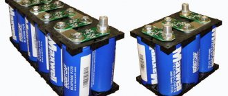
A hitherto unknown SIR has been found! Moreover, what surprises me is that this type was also produced in the late 90s, during the general collapse. Nevertheless…
There is no technical information on it, no information about the manufacturer.
(photo by Alexander Nazarenko)
Sources:
1. Ayolo B. M., Dmitriev Yu. S., Kogak A. V. Application of electrochemical resistance - memistor - for gain control. - In the book: Semiconductor electronics in communication technology. - M.: Svyaz, 1977. 2. Treyer V. .IN. Electrochemical devices. M., “Sov. radio", 1978. (Elements of radio-electronic equipment, issue 37) 3. Introduction to molecular electronics / N. S. Lidorenko, B. I. Ilyin, I. A. Zaidenman, etc.; Ed. N. S. Lidorenko. M.: Energoatomizdat, 1984.
CPU for circuit programming
When digital potentiometers are used to program various levels in circuits or for calibration in sensor devices, it is their state that determines the speed and accuracy of adjustment when connected to power.
There are many different types of CPUs on sale, differing in their ability to customize the power-on state, but there are only two main categories:
- Non-volatile crystal resistors that have a memory element. It is the latter that fixes the position of the engine when the device is connected.
- Energy dependent. These types of CPUs do not have memory, so in them the engine takes the position zero, middle or top when connected to power, depending on their design. To install it correctly, you should study the instructions with technical parameters.
The first versions of the CPU can be divided into 3 types according to the type of memory they use:
- Electrically erasable or reprogrammable (EEPROM). Data in them can be erased and rewritten an unlimited number of times.
- With a one-time program.
- Multiple programmable.
This division helps to select the optimal type of potentiometer for a specific circuit or system. So, in equipment where constant (frequent) adjustment is required, for example, the sound in an audio system, you can install a volatile option.
If you need to configure the parameters of the device once for its use, for example, factory settings, then the type with ORT is suitable. It remains unchanged for the entire duration of its operation.
A digital potentiometer can only accept the signal amplitude that is within its upper and lower supply voltage. If you plan to use it to conduct alternating current, then it is better to use resistors with bipolar power supply.
Recommendations
- Jafaripahah, M.; Al-Hashimi, B. M.; White, N. M. (2004, May). Consideration of the design and implementation of analog adaptive filters for correcting sensor response. Proceedings of ICEE2004.
- Greason, Geoffrey K. (1983). Voltage controlled resistance element with excellent dynamic range. US Patent US 5264785 A US 5264785 A
- Sherwin, Jim (1975, August).
- Wee, Keng Hungl; Sarpeshkar, Rahul (1986) JFET Ohmic Differential Amplifier, Keithley Instruments, US Patent.
- Schneider, Leif E.; Thompson, Kevin D. (2014). Self-optimizing energy harvester using a variable voltage source generator. Perpetua Power Source Technologies, Inc. US Patent US 8664931 B2.
- Sherwin, Jim (1975, August).
- Madaffari, Peter L. (2000). Amplifier with reduced input capacitance. Tibbetts Industries, Inc. US Patent US 6023194 A.
- Ballenger, Matthew; Kendrick, George (2006). A lamp with a built-in voltage converter, having a phase-controlled dimming circuit and containing a voltage-regulated resistor. Osram Sylvania, Inc. US Patent, US 20060082320 A1.
- Stoffer, C. Daniel W (1971). Balanced modulator with variable voltage JFET resistors. Collins Radio Company, US Patent US 3621473 A.
- Sung-Dae, Lee; Won-Hyo, Lee; Kang-Ming, Chung (1998). Linear voltage control resistor for neural chip. Systems, Man and Cybernetics, 1998. 1998 IEEE International Conference.
- Molina, Johnny F.; Stitt II, Mark; R., Bert, Rodney. (1994). Programmable gain amplifier circuit and Burr-Brown FET gain switch biasing method. US Patent US 5327098 A.
- Elektrosmash. Phase Analyzers 90 MXR. www.electrosmash.com.
- Tsai, Tsung-Hsien; Hung, Zong-Hsien, Chen, Jiang-Hung; Yuan, Ming-Shue (2010) Phase-locked loop (PLL) with gain control. Taiwanese semiconductor manufacturing company. US Patent US7786771 B2.
- Ballenger, Matthew B; Kendrick, George B. (2010). A lamp with a built-in voltage converter, having a phase-controlled dimming circuit and containing a voltage-regulated resistor. Osram Sylvania Inc., US Patent US 7839095 B2.
- Field-effect transistors as voltage-regulated resistors (1997, March). Vishay.
- Kumgern, Montri; Torteanchai, USA; Deyhan, Kobchay (2011, April). Voltage Adjustable Floating Resistor Using DDCC, RadioEngineering.
- McCarthy, Daniel P.; Connell, Lawrence E; Hollenbeck, Neil W. (2009) Linear voltage controlled variable attenuator with linear dB/V gain slope. FreeScale Semiconductor. US Patent US 20090143036 A1.
- Griffen, Jed D. (2002). Generator with high precision voltage control and RC circuit. Intel Corp. US Patent US 6498539 B2.
- High-voltage electrical stimulation apparatus for plants (2012). Chinese Patent CN 202285631 U.
- Simons, Pete (2013). Generation of digital signals. Cambridge University Press. P. 33.
- VCR11 Voltage controlled resistor. Linear integrated systems.
- Maxwell, John (1976), AN-6602Low Noise JFET - The Noise Problem Solver. Fairchild Semiconductor.
- Levinsohn, Felix (2014). Piezoelectric accelerometers with built-in electronics. Springer, p.75.
- Ian, Eric; Milic, Ognjen; Zhou, Jinghai (2011, November), Input Surge Protector Using JFET, Monolithic Power Systems, Inc. US Patent US 8068321 B2.
- Roundrey, Robert Newton (2014, November). JFET ESD protection circuit for low voltage applications. US Patent US 20140339608 A1.
- Field-effect transistors as voltage-regulated resistors (1997, March). Vishay.
- Field-effect transistors as voltage-regulated resistors (1997, March). Vishay.
- Wee, Keng Hungl; Sarpeshkar, Rahul (1986) FET ohmic differential amplifier, Keithley Instruments, US patent
- Kholani, Rani; Pandey, Prem C; Tiwari, Nitya (2014). JFET Based Circuit for Implementing Precision and Linear Constant Voltage Controlled Resistance, 2014 IEEE India Annual Conference (INDICON).
- David Kleinfeld Research Laboratory at the University of California, San Diego. A field-effect transistor is like a voltage-controlled resistor. https://neurophysics.ucsd.edu/courses/physics_120/The%20Field%20Effect%20Transistor%20as%20a%20Voltage%20Controlled%20Resistor.pdf
- Liao, Yihua. Neural Networks in Hardware: An Overview, Analog Neurochips, Section 5.3.2, University of California, Davis.
- Zhang, Xiaolin; Maeda, Yoshinori (2012). Equivalent Nerve Circuit Equivalent Synapse Circuit and Nerve Cell Body Tokyo Institute of Technology. US Patent US 8112373 B2.
- Rice University (2016, June), RedEye can let your phone see 24-7. Science Daily.
- Quan, Ron. A Guide to Using JFET Sensors for Sensor Applications. Linear systems.