Home > Theory > Calculation of the inductor
Inductors are designed to filter high frequency currents. They are installed in oscillating circuits and are used for other purposes in electrical and electronic circuits. A ready-made factory-made device is more reliable in operation, but more expensive than one made by hand. In addition, it is not always possible to purchase an element with the necessary characteristics. In this case, the calculation of the inductor and the device itself can be done independently.
Inductor coil design
Design
The main purpose of inductors GOST 20718-75 is the accumulation of electrical energy within a magnetic field for acoustics, transformers, etc. They are used for the development and construction of various selective circuits and electrical devices. Their functionality, size and area of use depend on the design (material, number of turns), the presence of a frame. The devices are manufactured in factories, but you can make them yourself. Homemade elements are somewhat inferior in reliability to professional ones, but are several times cheaper.
Photo - diagram
The frame of the inductor is made of dielectric material. An insulated conductor is wound around it, which can be either single-core or multi-core. Depending on the type of winding, they are:
- Spiral (on a ferrite ring);
- Screw;
- Screw-spiral or combined.
A notable feature of an inductor for electrical circuits is that it can be wound either in several layers or unified, i.e., with scraps. If a thick conductor is used, then the element can be wound without a frame, if thin, then only on a frame. These inductor frames come in different cross-sections: square, round, rectangular. The resulting winding can be inserted into a special housing of any electrical device or used openly.
Photo - design of a homemade element
Cores are used to increase inductance. Depending on the purpose of the element, the rod material used varies:
- With ferromagnetic and air cores they are used at high current frequencies;
- Steel ones are used in low voltage environments.
Based on the principle of operation, there are the following types:
- Contour. They are mainly used in radio engineering to create oscillatory circuits on boards and work together with capacitors. The connection uses a serial connection. This is a modern version of the flat Tesla coil;
- Variometers. These are high-frequency tunable coils, the inductance of which can be controlled, if necessary, using additional devices. They represent a connection of two separate coils, one of which is movable and the other is not;
- Twin and tuning chokes. The main characteristics of these coils: low resistance to direct current and high resistance to alternating current. Chokes are made of several coils connected by windings. They are often used as a filter for various radio devices, installed to control interference in antennas, etc.;
- Communication transformers. Their design feature is that two or more coils are installed on one rod. They are used in transformers to provide a specific connection between the individual components of a device.
The marking of inductors is determined by the number of turns and the color of the housing.
Photo – marking
Making a throttle
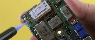
To make a choke, you need to choose a suitable frame - in our case, this is a resistor of a certain power and, accordingly, dimensions. Below are photos of domestic and foreign resistors with the designation of their power.
Rice. 2. MLT resistors and foreign power resistors.
Rice. 3. An example of winding a choke on an MLT-0.5 resistor.
Resistors with high resistance are suitable for winding the inductor, for example: 100 kOhm, 200 kOhm, etc.
It is important that the resistor resistance is large, otherwise the quality factor of your homemade inductor may turn out to be poor
An example of winding in uniform layers is shown in Figure 3.
For winding, you can use thin enameled wire (PETV) or silk-insulated wire (PELSHO) with a diameter of 0.1-0.2 mm; it is important that all the turns wound with such wire fit on our resistor frame. After winding, each end of the wire is soldered to the terminals of the resistor, and you can drip a little glue onto the coil on top so that the turns do not spread later
After winding, each end of the wire is soldered to the terminals of the resistor, and you can drip a little glue onto the coil on top so that the turns do not spread later.
Operating principle
The operation scheme of active inductors is based on the fact that each individual turn of the winding intersects with magnetic lines of force. This electrical element is necessary in order to extract electrical energy from a power source and convert it to store it in the form of an electric field. Accordingly, if the circuit current increases, then the magnetic field expands, but if it decreases, the field will invariably contract. These parameters also depend on frequency and voltage, but in general, the effect remains unchanged. Turning on the element produces a phase shift in current and voltage.
Photo - principle of operation
In addition, inductive (frame and frameless) coils have the property of self-induction, its calculation is made based on the data of the nominal network. In multilayer and single-layer windings, a voltage is created that is opposite to the voltage of the electric current. This is called EMF; the determination of electromotive magnetic force depends on inductance values. It can be calculated using Ohm's law. It is worth noting that regardless of the network voltage, the resistance in the inductor does not change.
Photo - connection of individual terminals of elements
The connection between inductance and the concept (change) of emf can be found using the formula ε c = – dФ/dt = – L*dI/dt, where ε is the value of self-induction emf. And if the rate of change of electrical energy is equal to dI/dt = 1 A/c, then L = ε c.
Video: calculating an inductor
Project Development Resources
The implementation of inductance with a flat wire is essentially no different from the version with a round wire. This is the same inductor, but with a smaller housing and higher possible current ratings. The choice of low profile inductor depends on the technical requirements of the specific application. Several resources are available to help you select the right component. An example of a DC/DC buck converter circuit is shown below, with the inductance symbol L in the diagram.
Rice. 4. DC/DC buck circuit based on flat wire inductance
Online DC/DC converter design software can be found on many DC/DC controller manufacturer websites. An example is the Webench software tool created by National Semiconductor Texas Instruments in 2011 . The developer uploads detailed design information, including power supply input and output voltage, output current, and efficiency. The program then suggests the chipset and provides a database from which you can select supporting components. Bourns inductors are built into the Webench database, allowing the designer to select the correct component for the converter being designed. Texas Instruments (TI) offers SwitcherPro, a program that includes a database of all Bourns surface mount inductors to support TI chipsets in converter designs. In addition, Bourns has its own parametric search tool on its website. The designer is asked to specify the inductance and current rating, then the program will suggest a number of components that will meet the specified requirements. Studying the detailed technical descriptions of this series will allow the designer to fine-tune the parametric search to select the desired inductor. In addition, Bourns has prepared seven types of SRP inductor development kits to support new developments and has announced additional development kits will be available soon. To obtain a kit for your project, the developer must contact Bourns distributors.
Calculation
Formula – formula of an oscillatory circuit
Where L is the element itself, which accumulates magnetic energy.
At the same time, the period of free oscillations of this circuit is calculated by:
Formula – period of free oscillations
Where C is a capacitor, a reactive element of the circuit that stores electrical energy in a particular circuit. The amount of inductive reactance in such a circuit is calculated by XL = U/I. Here X is the capacitance. When calculating a resistor, the main parameters of this element are inserted into the example.
The inductance of the solenoid is determined by the formula:
Formula - inductance of the solenoid coil
In addition, the inductance level has a certain dependence on the temperature on the board. Parallel connection of several parts, changes in the density and size of winding turns and other parameters affect the basic properties of this element.
Photo – temperature dependence
To find out the parameters of the inductor, you can use various methods: measure with a multimeter, test with oscilloscopes, check separately with an ammeter or voltmeter. These options are very convenient because they use capacitors as reactive elements, the electrical losses of which are very small and may not be taken into account in the calculations. Sometimes, in order to simplify the task, a special program for calculating and measuring the required parameters is used. This allows you to significantly simplify the selection of the necessary elements for the circuits.
You can buy inductors (SMD 150 μH and others) and wires for winding them at any electrical store; their price varies from $2 to several dozen.
Inductors are designed to filter high frequency currents. They are installed in oscillating circuits and are used for other purposes in electrical and electronic circuits. A ready-made factory-made device is more reliable in operation, but more expensive than one made by hand. In addition, it is not always possible to purchase an element with the necessary characteristics. In this case, the calculation of the inductor and the device itself can be done independently.
Coil design
The frame of the device is made of dielectric. This can be thin (non-foil) getinaks, textolite, and on toroidal cores - just a winding made of varnished fabric or a similar material.
The winding is made of single-core or multi-core insulated wire.
A core is inserted inside the winding. It is made of iron, transformer steel, ferrite and other materials. It can be closed, toroidal (donut), square or open (rod). The choice of material depends on operating conditions: frequency, magnetic flux and other parameters.
Electric current flowing through a wire creates an electromagnetic field around it. The ratio of the field strength to the current strength is called inductance. If the wire is rolled into a ring or wound around a frame, you get an inductor. Its parameters are calculated using certain formulas.
Calculation of inductance of a straight wire
The inductance of a straight rod is 1-2 μH per meter. It depends on its diameter. More precisely, it can be calculated using the formula:
L=0.2l(logl/d-1), where:
- d – wire diameter,
- l – wire length.
These values must be measured in meters (m). In this case, the result will have the dimension of microhenry (μH). Instead of the natural logarithm ln, it is permissible to use the decimal lg, which is 2.3 times smaller.
Let's assume that some part is connected with wires 4 cm long and 0.4 mm in diameter. Using a calculator to calculate using the above formula, we find that the inductance of each of these wires will be (rounded) 0.03 μH, and of two – 0.06 μH.
The mounting capacitance is about 4.5 pF. In this case, the resonant frequency of the resulting circuit will be 300 MHz. This is the VHF band.
Important!
Therefore, when installing devices operating at VHF frequencies, the length of the lead parts must be kept to a minimum.
Calculation of single-layer winding
To increase the inductance, the wire is rolled into a ring. The magnitude of the magnetic flux inside the ring is approximately three times higher. It can be calculated using the following expression:
L = 0.27D(ln8D/d-2), where D is the diameter of the ring, measured in meters.
As the number of turns increases, the inductance continues to increase. In this case, the induction of individual turns affects neighboring ones, therefore the resulting parameters are proportional not to the number of turns N, but to their square.
Core choke
The parameters of a winding wound on a frame with a diameter much smaller than the length are calculated using the formula:
It is valid for a device of great length or a large torus.
The dimensions in it are given in meters (m) and henry (H). Here:
- 0 = 4 10-7 H/m – magnetic constant,
- S = D2/4 – cross-sectional area of the winding, magnetic permeability of the magnetic core, which is less than the permeability of the material itself and takes into account the length of the core; in an open structure it is much less than that of the material.
For example, if the antenna rod is made of ferrite with a permeability of 600 (grade 600NN), then the resulting product will have a permeability of 150. In the absence of a magnetic core = 1.
In order to use this expression to calculate windings wound on a toroidal core, it must be measured along the center line of the donut. When calculating windings wound on W-shaped iron without an air gap, the length of the magnetic flux path is measured along the centerline of the core.
The diameter of the wire is not taken into account in the calculation, therefore, in low-frequency designs, the wire cross-section is selected according to tables based on the permissible heating of the conductor.
In high-frequency devices, as well as in others, they strive to reduce the ohmic resistance to a minimum in order to achieve maximum quality factor of the device. Simply increasing the wire gauge does not help. This leads to the need to wind the winding in several layers. But the RF current flows predominantly along the surface, which leads to an increase in resistance. The quality factor in high-frequency elements increases along with an increase in all dimensions: the length and diameters of the winding and wire.
The maximum quality factor is obtained in a short winding of large diameter, with a diameter/length ratio of 2.5. The parameters of such a device are calculated by the formula:
L=0.08D2N2/(3D+9b+10c).
In this formula, all parameters are measured in centimeters (cm), and the result is obtained in microhenry (µH).
This formula is also used to calculate a flat coil. Diameter “D” is measured along the middle turn, and length “l” is measured along the width:
Multilayer winding
Multilayer winding without a core is calculated by the formula:
L=0.08D2N2/(3D+9b+10c).
Dimensions here are measured in centimeters (cm), and the result is obtained in microhenry (µH).
The quality factor of such a device depends on the winding method:
- regular tight winding is the worst, no more than 30-50;
- bulk and station wagon;
- “cellular”.
To increase the quality factor at frequencies up to 10 MHz, instead of a conventional single-core wire, you can use Litz wire or a silver-plated conductor.
Reference.
Litz wire is a wire twisted from a large number of thin wires insulated from each other.
Litz wire has a larger surface area compared to a single-core conductor of the same cross-section, so at high frequencies its resistance is lower.
The use of a core in high-frequency devices increases the inductance and quality factor of the coil. The use of closed cores has a particularly great effect. In this case, the quality factor of the inductor depends not on the active resistance of the wire, but on the permeability of the magnetic circuit. Such a device is calculated using the usual formulas for low-frequency devices.
You can make a coil or choke yourself. Before making it, you need to calculate the inductance of the coil using formulas or using an online calculator.
How to determine the effective magnetic permeability of a core with a gap
The effective magnetic permeability of a core with a gap μe is associated with such a concept as magnetic flux resistance Rm, which is similar to electrical resistance in that it depends on the length and cross-section of the magnetic circuit (electrical resistance depends on the length and cross-section of the electrical conductor). The magnetic flux resistance is given by the following expression
From this expression we can conclude that the lower the magnetic permeability of the material, the higher the magnetic resistance. It is not difficult to notice that taking into account the relative magnetic permeability of the core substance (of the order of several thousand) and air (approximately equal to unity), the magnetic resistance of the core with a gap will be largely determined by the size of the air gap.
Thus, the total magnetic resistance of the core with a gap RO will consist of the series magnetic resistance of the core RC and the magnetic resistance of the gap RЗ. Taking into account the fact that the relative magnetic permeability of air is approximately equal to one μr = 1, we obtain the following expression
where μ is the magnetic constant, μ0 = 4π*10-7,
μе – equivalent magnetic permeability of the core with a gap,
μr – absolute magnetic permeability of the core substance,
Se is the effective cross-sectional area of the core,
le is the effective path of the magnetic line of the core,
l is the length of the magnetic field line of the core with a gap,
δ is the length of the air gap.
After transformation we get
Since the length of the gap is less than the length of the magnetic line of the core (δ << le), then from this expression we can obtain an expression for the effective magnetic permeability of the core with a gap
where μе is the equivalent magnetic permeability of the core with a gap,
μr – absolute magnetic permeability of the core substance,
le is the effective path of the magnetic line of the core,
δ is the length of the air gap.
This expression shows that the effective magnetic permeability of the core with a gap, and, consequently, the inductance of the coil and other constant parameters, decreases with increasing gap size.
Video
The inductor as a radio-electronic element is quite common. Sometimes it is irreplaceable, for setting up many radios and is used in many devices. It should be noted that for exclusive things, sometimes it is not possible to get exclusive coils, so you need to know not only the structure of an inductor and the formulas for its calculation, but also be able to make inductors yourself. In this article, any novice radio amateur will find a couple of useful tips for himself.
Main settings
The main characteristics of the inductor include:
- Inductance.
- Current strength (to select a suitable element during repair and design, this must be taken into account).
- Loss resistance (in wires, in core, in dielectric).
- Quality factor is the ratio of reactance to active resistance.
- Parasitic capacitance (capacitance between turns, in simple terms).
- Temperature coefficient of inductance - the change in inductance when an element is heated or cooled.
- Temperature quality factor.
How to fill an inductor with wax:
By assembling a circuit in which there is an oscillating circuit, setting up a radio receiver or transmitter (anything) or making any other circuit (winding, for example, high-voltage coils). You need to adjust the distance between the turns of the coil. When you have set up your circuit, to avoid unwanted changes in the parameters of the coil due to mechanical displacement of the turns, you just need to fill the coil with ordinary wax or paraffin (if the coil does not heat up) Figure No. 3.
Figure No. 3 - Example of a wax-filled coil
You can fill the coils with epoxy resin or silicone - it all depends on the conditions under which your inductor must operate. And what is at your fingertips. In the case of wax (paraffin), all you need to do is melt it and just wait for it to cool down by first lowering the inductor into it.
In order to create a magnetic field and smooth out interference and impulses in it, special storage elements are used. Inductors in AC and DC circuits are used to store a certain amount of energy and limit electricity.
Design
The main purpose of inductors GOST 20718-75 is the accumulation of electrical energy within a magnetic field for acoustics, transformers, etc. They are used for the development and construction of various selective circuits and electrical devices. Their functionality, size and area of use depend on the design (material, number of turns), the presence of a frame. The devices are manufactured in factories, but you can make them yourself. Homemade elements are somewhat inferior in reliability to professional ones, but are several times cheaper.
Photo - diagram
The frame of the inductor is made of dielectric material. An insulated conductor is wound around it, which can be either single-core or multi-core. Depending on the type of winding, they are:
- Spiral (on a ferrite ring);
- Screw;
- Screw-spiral or combined.
A notable feature of an inductor for electrical circuits is that it can be wound either in several layers or unified, i.e., with scraps. If a thick conductor is used, then the element can be wound without a frame, if thin, then only on a frame. These inductor frames come in different cross-sections: square, round, rectangular. The resulting winding can be inserted into a special housing of any electrical device or used openly.
Photo - design of a homemade element
Cores are used to increase inductance. Depending on the purpose of the element, the rod material used varies:
- With ferromagnetic and air cores they are used at high current frequencies;
- Steel ones are used in low voltage environments.
Based on the principle of operation, there are the following types:
- Contour. They are mainly used in radio engineering to create oscillatory circuits on boards and work together with capacitors. The connection uses a serial connection. This is a modern version of the flat Tesla coil;
- Variometers. These are high-frequency tunable coils, the inductance of which can be controlled, if necessary, using additional devices. They represent a connection of two separate coils, one of which is movable and the other is not;
- Twin and tuning chokes. The main characteristics of these coils: low resistance to direct current and high resistance to alternating current. Chokes are made of several coils connected by windings. They are often used as a filter for various radio devices, installed to control interference in antennas, etc.;
- Communication transformers. Their design feature is that two or more coils are installed on one rod. They are used in transformers to provide a specific connection between the individual components of a device.
The marking of inductors is determined by the number of turns and the color of the housing.
Photo – marking
Making a throttle
To make a choke, you need to choose a suitable frame - in our case, this is a resistor of a certain power and, accordingly, dimensions. Below are photos of domestic and foreign resistors with the designation of their power.
Rice. 2. MLT resistors and foreign power resistors.
Rice. 3. An example of winding a choke on an MLT-0.5 resistor.
Resistors with high resistance are suitable for winding the inductor, for example: 100 kOhm, 200 kOhm, etc.
It is important that the resistor resistance is large, otherwise the quality factor of your homemade inductor may turn out to be poor
An example of winding in uniform layers is shown in Figure 3.
For winding, you can use thin enameled wire (PETV) or silk-insulated wire (PELSHO) with a diameter of 0.1-0.2 mm; it is important that all the turns wound with such wire fit on our resistor frame. After winding, each end of the wire is soldered to the terminals of the resistor, and you can drip a little glue onto the coil on top so that the turns do not spread later
After winding, each end of the wire is soldered to the terminals of the resistor, and you can drip a little glue onto the coil on top so that the turns do not spread later.
Operating principle
The operation scheme of active inductors is based on the fact that each individual turn of the winding intersects with magnetic lines of force. This electrical element is necessary in order to extract electrical energy from a power source and convert it to store it in the form of an electric field. Accordingly, if the circuit current increases, then the magnetic field expands, but if it decreases, the field will invariably contract. These parameters also depend on frequency and voltage, but in general, the effect remains unchanged. Turning on the element produces a phase shift in current and voltage.
Photo - principle of operation
In addition, inductive (frame and frameless) coils have the property of self-induction, its calculation is made based on the data of the nominal network. In multilayer and single-layer windings, a voltage is created that is opposite to the voltage of the electric current. This is called EMF; the determination of electromotive magnetic force depends on inductance values. It can be calculated using Ohm's law. It is worth noting that regardless of the network voltage, the resistance in the inductor does not change.
Photo - connection of individual terminals of elements
The connection between inductance and the concept (change) of emf can be found using the formula ε c = – dФ/dt = – L*dI/dt, where ε is the value of self-induction emf. And if the rate of change of electrical energy is equal to dI/dt = 1 A/c, then L = ε c.
Video: calculating an inductor
Calculation
Formula – formula of an oscillatory circuit
Where L is the element itself, which accumulates magnetic energy.
At the same time, the period of free oscillations of this circuit is calculated by:
Formula – period of free oscillations
Where C is a capacitor, a reactive element of the circuit that stores electrical energy in a particular circuit. The amount of inductive reactance in such a circuit is calculated by XL = U/I. Here X is the capacitance. When calculating a resistor, the main parameters of this element are inserted into the example.
The inductance of the solenoid is determined by the formula:
Formula - inductance of the solenoid coil
In addition, the inductance level has a certain dependence on the temperature on the board. Parallel connection of several parts, changes in the density and size of winding turns and other parameters affect the basic properties of this element.
Photo – temperature dependence
To find out the parameters of the inductor, you can use various methods: measure with a multimeter, test with oscilloscopes, check separately with an ammeter or voltmeter. These options are very convenient because they use capacitors as reactive elements, the electrical losses of which are very small and may not be taken into account in the calculations. Sometimes, in order to simplify the task, a special program for calculating and measuring the required parameters is used. This allows you to significantly simplify the selection of the necessary elements for the circuits.
You can buy inductors (SMD 150 μH and others) and wires for winding them at any electrical store; their price varies from $2 to several dozen.
What do you mean by the word “reel”? Well... this is probably some kind of “fig” on which threads, fishing line, rope, whatever! An inductor coil is exactly the same thing, but instead of a thread, fishing line or anything else, ordinary copper wire in insulation is wound there.
The insulation can be made of clear varnish, PVC insulation, or even fabric. The trick here is that even though the wires in the inductor are very close to each other, they are still isolated from each other
. If you wind inductor coils with your own hands, do not under any circumstances even think about using ordinary bare copper wire!
Inductance
Any inductor has inductance
.
The inductance of the coil is measured in Henry
(H), denoted by the letter
L
and measured using an LC meter.
What is inductance? If an electric current is passed through a wire, it will create a magnetic field around itself:
Where
B – magnetic field, Wb
I –
Let's take this wire and wind it into a spiral and apply voltage to its ends
And we get this picture with magnetic lines of force:
Roughly speaking, the more magnetic field lines cross the area of this solenoid, in our case the area of the cylinder, the greater the magnetic flux (F)
.
Since an electric current flows through the coil, it means that a current with Current Strength (I) passes through it,
and the coefficient between the magnetic flux and the current strength is called inductance and is calculated by the formula:
From a scientific point of view, inductance is the ability to extract energy from a source of electric current and store it in the form of a magnetic field. If the current in the coil increases, the magnetic field around the coil expands, and if the current decreases, the magnetic field contracts.
Self-induction
The inductor also has a very interesting property. When a constant voltage is applied to the coil, an opposite voltage appears in the coil for a short period of time.
This opposite voltage is called self-induced emf.
This depends on the inductance value of the coil. Therefore, at the moment the voltage is applied to the coil, the current gradually changes its value from 0 to a certain value within a fraction of a second, because the voltage, at the moment the electric current is applied, also changes its value from zero to a steady value. According to Ohm's Law:
Where
I
– current strength in the coil, A
U
– voltage in the coil, V
R
– coil resistance, Ohm
As we can see from the formula, the voltage changes from zero to the voltage supplied to the coil, therefore the current will also change from zero to some value. The coil resistance for DC is also constant.
And the second phenomenon in the inductor is that if we open the circuit between the inductor and the current source, then our self-induction emf will be added to the voltage that we have already applied to the coil.
That is, as soon as we break the circuit, the voltage on the coil at that moment can be many times greater than it was before the circuit was broken, and the current strength in the coil circuit will quietly fall, since the self-induction emf will maintain the decreasing voltage.
Let us draw the first conclusions about the operation of the inductor when DC current is supplied to it. When electric current is supplied to the coil, the current strength will gradually increase, and when electric current is removed from the coil, the current strength will smoothly decrease to zero. In short, the current strength in the coil cannot change instantly.
Types of Inductors
Inductors are divided mainly into two classes: with magnetic and non-magnetic cores
. Below in the photo is a coil with a non-magnetic core.
But where is her core? Air is a non-magnetic core :-). Such coils can also be wound on some cylindrical paper tube. Inductance coils with a non-magnetic core are used when the inductance does not exceed 5 millihenry.
And here are the inductors with a core:
Cores made of ferrite and iron plates are mainly used. The cores increase the inductance of the coils significantly.
Cores in the form of a ring (toroidal) allow you to obtain higher inductance than just cylinder cores.
For medium inductance coils, ferrite cores are used:
Coils with high inductance are made like a transformer with an iron core, but with one winding, unlike a transformer.
Chokes
There is also a special type of inductor. These are the so-called. An inductor is an inductor whose job is to create a high resistance to alternating current in the circuit in order to suppress high frequency currents.
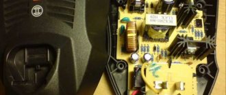
Direct current passes through the inductor without problems. You can read why this happens in this article. Typically, chokes are connected in the power supply circuits of amplifying devices. Chokes are designed to protect power supplies from high frequency signals (RF signals). At low frequencies (LF) they are used in power supply circuits and usually have metal or ferrite cores. Below in the photo are power chokes:
There is also another special type of chokes - this. It consists of two counter-wound inductors. Due to counter-winding and mutual induction, it is more efficient. Twin chokes are widely used as input filters for power supplies, as well as in audio technology.
Experiments with a coil
On what factors does the inductance of the coil depend? Let's do some experiments. I wound a coil with a non-magnetic core. Its inductance is so small that the LC meter shows zero to me.
Has a ferrite core
I begin to insert the coil into the core to the very edge
The LC meter reads 21 microhenry.
I insert the coil into the middle of the ferrite
35 microhenry. Already better.
I continue to insert the coil onto the right edge of the ferrite
20 microhenry. We conclude that the largest inductance on a cylindrical ferrite occurs in its middle.
Therefore, if you wind on a cylinder, try to wind in the middle of the ferrite. This property is used to smoothly change the inductance in variable inductors:
Where
1 – this is the coil frame
2 – these are the turns of the coil
3 – core, which has a groove on top for a small screwdriver. By screwing or unscrewing the core, we thereby change the inductance of the coil.
The inductance has become almost 50 microhenry!
Let's try to straighten the turns throughout the ferrite
13 microhenry. We conclude: for maximum inductance, the coil must be wound “turn to turn”.
Let's reduce the turns of the coil by half. There were 24 orbits, now there are 12.
Very low inductance. I reduced the number of turns by 2 times, the inductance decreased by 10 times. Conclusion: the lower the number of turns, the lower the inductance and vice versa. Inductance does not change linearly across turns.
Let's experiment with a ferrite ring.
We measure inductance
15 microhenry
Let's move the coil turns away from each other
Let's measure again
Hmm, also 15 microhenry. We conclude: the distance from turn to turn does not play any role in a toroidal inductor.
Let's make more turns. There were 3 turns, now there are 9.
We measure
Wow! Increased the number of turns by 3 times, and the inductance increased by 12 times! Conclusion: inductance does not change linearly across turns.
If you believe the formulas for calculating inductances, the inductance depends on the “turns squared”.
I won’t post these formulas here, because I don’t see the need. I will only say that inductance also depends on such parameters as the core (what material it is made of), the cross-sectional area of the core, and the length of the coil.
Designation on diagrams
Series and parallel connection of coils
When connecting inductors in series
, their total inductance will be equal to the sum of the inductances.
And with a parallel connection
we get this:
When connecting inductors, the rule must be followed so that they are spatially separated on the board.
This is because if they are close to each other, their magnetic fields will influence each other and therefore the readings of the inductances will be incorrect. Do not place two or more toroidal coils on one iron axis. This may result in incorrect total inductance readings.
Features of using chokes in circuits
The chokes can be connected in series or in parallel.
[Inductance of series-connected chokes
] = [
Inductance of the first choke
] + [
Inductance of the second choke
]
[Inductance of parallel connected chokes
] = 1 / (1 / [
Inductance of the first choke
] + 1 / [
Inductance of the second choke
])
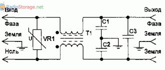
The figure shows typical circuits using inductors. (A) - Inductive AC voltage divider. [ Lower throttle voltage
] = [
Input voltage
] * [
inductance of the lower choke
] / ([
inductance of the lower choke
] + [
inductance of the upper choke
]) (B) - High-pass filter. (B) — Low-pass filter.
(read more...) :: (to the beginning of the article)
| 1 | 2 | 3 |
:: SearchSafety :: Help
Unfortunately, errors are periodically found in articles; they are corrected, articles are supplemented, developed, and new ones are prepared. Subscribe to the news to stay informed.
If something is unclear, be sure to ask!Ask a question. Discussion of the article. messages.
Here is one formula = * * / /, according to which it turns out that the greater the current through the inductor, the greater the number of turns - which fundamentally contradicts the theory - the more current is needed, the smaller the number of turns should be (THIS Read the answer...
And what is E in the first formula, it just turns out to be a huge amount of inductance. In the first formula, it is plausible if the inductance is in microhenry. If I understand correctly, then, for example, E-3 means 0.001? Read the answer...
How to calculate and make an RF choke yourself, with an inductance of 5 μH, for a current of 3-4A? Read the answer...
More articles
Power powerful pulse transformer, choke. Winding. Make... Techniques for winding a pulse inductor / transformer....
Inverter, converter, pure sine wave, sine... How to get a pure 220 volt sine wave from a car battery in order to...
Single-phase to three-phase converter. Converter of one phase to three. ... Single-phase to three-phase voltage converter circuit....
Resonant inverter, voltage boost converter. Circuit, co... Inverter 12/24 to 300. Resonant circuit....
A simple pulse forward voltage converter. 5 - 12 volts... Circuit of a simple voltage converter to power an operational amplifier....
Diode circuits. Circuit solutions. Circuit design. Frequency, power, noise…. Classification, types of semiconductor diodes. Schemes, circuit solutions using diodes. ...
Step-down switching power supply. Online payment. Form. Suppressed... How to calculate a step-down switching voltage converter. How to suppress pu...
Checking electronic elements and radio components. Check serviceability, r... How to check the serviceability of a part. Test method. What parts can be used...