Circuit design is a modern and rather complex science with a high threshold for entry in terms of qualification level. Some people try to master it on their own, but, as a rule, it doesn’t go beyond assembling simple electronic circuits and repairing household appliances. To successfully assemble boards on your own, applicants for the title of amateur radio operator must have basic knowledge of physics, as well as be able to correctly determine the rating of a particular electronic component.
If the area of the capacitor or resistor allows, then the main characteristics of the product are almost always marked on such elements, otherwise a novice designer and assembler of devices may encounter insurmountable difficulties. This article will talk about how to find out the capacitance of an SMD capacitor, as well as ways to determine other parameters of this type of product.
What are SMD capacitors
Overall dimensions, mm)
CA Series
| Code | ФD | L | A | H | I | W | P | K |
| A | 3,0 | 5,4 | 3,3 | 4.5 max | 1,5 | 0,55±0,1 | 0,6 | 0,35+0,15 (-0,20) |
| B | 4,0 | 5,4 | 4,3 | 5.5 max | 1,8 | 0,65±0,1 | 1,0 | 0,35+0,15 (-0,20) |
| C | 5,0 | 5,4 | 5,3 | 6.5 max | 2,2 | 0,65±0,1 | 1,5 | 0,35+0,15 (-0,20) |
| D | 6,3 | 5,4 | 6,6 | 7.8 max | 2,6 | 0,65±0,1 | 2,2 | 0,35+0,15 (-0,20) |
| E | 8,0 | 6,2 | 8,3 | 9.4 max | 3,4 | 0,65±0,1 | 2,2 | 0,35+0,15 (-0,20) |
| F | 8,0 | 10,2 | 8,3 | 10.0 max | 3,4 | 0,90±0,2 | 3,1 | 0,70±0,20 |
| G | 10,0 | 10,2 | 10,3 | 12.0 max | 3,5 | 0,90±0,2 | 4,6 | 0,70±0,20 |
CB Series
| Code | ФD | L | A | H | I | W | P | K |
| B | 4,0 | 5,4 | 4,3 | 5.5 max | 1,8 | 0,65±0,1 | 1,0 | 0,35+0,15 (-0,20) |
| C | 5,0 | 5,4 | 5,3 | 6.5 max | 2,2 | 0,65±0,1 | 1,5 | 0,35+0,15 (-0,20) |
| D | 6,3 | 5,4 | 6,6 | 7.8 max | 2,6 | 0,65±0,1 | 2,2 | 0,35+0,15 (-0,20) |
| E | 8,0 | 6,2 | 8,3 | 9.5 max | 3,4 | 0,65±0,1 | 2,2 | 0,35+0,15 (-0,20) |
| F | 8,0 | 10,2 | 8,3 | 10.0 max | 3,4 | 0,90±0,2 | 3,1 | 0,70±0,20 |
| G | 10,0 | 10,2 | 10,3 | 12.0 max | 3,5 | 0,90±0,2 | 4,6 | 0,70±0,20 |
Resistors
Passive Components: Resistors
| TYPE: | Type Explanation: | |||||
| S.R. | Resistor Chip Resistor chip | |||||
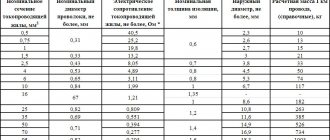
| Size (inches) | Size(mm) | Component Thickness | Tape width | Component pitch in the ribbon | Quantity in standard packaging (180 mm/7 inches) paper tape | Qty per standard package (180 mm/7 inches) plastic tape |
| 01005 | 0402 | 0.12 mm ± 0.02 | 8 mm | 2 mm | 20000 | — |
| 0201 | 0603 | 0.23 mm ± 0.03 | 8 mm | 2 mm | 15000 | — |
| 0402 | 1005 | 0.35 mm ± 0.05 | 8 mm | 2 mm | 10000 | — |
| 0603 | 1608 | 0.45 mm ± 0.1 | 8 mm | 4 mm | 5000 | — |
| 0805 | 2012 | 0.55 mm ± 0.1 | 8 mm | 4 mm | 5000 | — |
| 1206 | 3216 | 0.55 mm ± 0.15 | 8 mm | 4 mm | 5000 | — |
| 1210 | 3225 | 0.55 mm ± 0.15 | 8 mm | 4 mm | 5000 | 4000 |
| 2010 | 5025 | 0.55 mm ± 0.15 | 8/12 mm | 4/8 mm | — | 4000 |
| 2512 | 6332 | 0.55 mm ± 0.15 | 12 mm | 4/8 mm | — | 4000/2000 |
Passive Components: Resistors
| TYPE: | Type Explanation: | ||||
| SRM | Melf Resistor Melf resistor (round) | ||||
| Size (inches) | Name | Component size | Tape width | Component pitch in the ribbon | Qty per standard package (180 mm/7 inches) plastic tape |
| 0604 | — | 1.6 mm X 1.0 mm | 8 mm | 4 mm | 3000 |
| 0805 | Micro | 2.2 mm X 1.1 mm | 8 mm | 4 mm | 3000 |
| 1206 | Mini | 3.2 mm X 1.6 mm | 8 mm | 4 mm | 3000 |
| 1406 | Mini | 3.5 mm X 1.4 mm | 8 mm | 4 mm | 3000 |
| 2308 | Melf | 5.9 mm X 2.2 mm | 12 mm | 4 mm | 1500 |
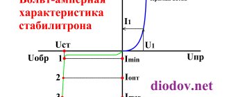
Checking with a multimeter
The simplest and at the same time affordable way of testing is to check with a multimeter. This device is capable of measuring various electrical quantities, from resistance to voltage and frequency. In particular, it can also measure the capacitance of a capacitor. Capacity testing is not instantaneous. The tester needs time to charge the cell to a certain voltage level and then discharge it. Based on the magnitude of the discharge current and time, a conclusion about the capacity is made.
Capacitance measurement
Before installing any elements into equipment during repair or design, it is necessary to test their serviceability and compliance with the specified parameters. Therefore, you need to know how to test the capacitance of a capacitor with a multimeter. You need to follow a few simple steps:
- Install the multimeter test leads into the appropriate holes on its body. The black probe goes into the hole marked COM, and the red one goes into the socket marked Ohm, Hz, U.
- Select the capacitor testing mode using the knob on the front panel of the device. Typically, this mode is indicated by the symbol of an electric capacitor - two parallel lines with leads.
- Touch the probes of the multimeter to the terminals of the element. In this case, the value of its capacitance in microfarads should be displayed on the tester screen. Usually the measuring device shows in what quantities the measurement is being made, or this data is on its measuring scale.
- If the obtained value differs from the nominal value by more than the tolerance specified in the description of this type of electric capacitor (can be from 0.5 to 80%), then the element should not be used for its intended purpose.
Knowing how to measure the capacitance of a capacitor with a multimeter is also necessary when checking an electrical appliance for errors in operation. Any electrical device may begin to operate unstably, and the reason for this may be the failure of one or more elements. If you measure the capacitance of the capacitors used in the device, you can identify and eliminate the cause of the malfunction.
Resistance test
You can also find out whether a breakdown of an element has occurred by measuring its resistance. Some measuring instruments do not have the ability to check the capacitance of electrical capacitors. But with such meters you can still test the equipment if you measure the resistance between the plates of the capacitors used in it.
To do this, you need to perform all the steps described for checking the capacitance, but you need to select a different measurement mode - resistance testing. This mode is usually indicated by the measurement range in Ohms. To test capacitors, it is better to choose a range of 200 Ohms. If, when testing an element, a resistance below 50 Ohms is detected, such an element has suffered a breakdown and cannot be used.
You can also ring an element inside the circuit, directly in the equipment. However, testing a capacitor with a multimeter without unsoldering any of its legs leads to measurement errors, since the rest of the circuit located between the test leads is also tested. Therefore, to measure, you need to unsolder at least one of the element’s terminals.
Knowing how to test a capacitor with a multimeter without desoldering is necessary when painstakingly checking electrical devices for a possible malfunction, if it is known for sure that the malfunction lies in one of the elements. In this case, you should unsolder one of the legs of each element and measure their resistance and capacitance one by one. In this way, faulty elements can be identified.
Originally posted 2018-07-04 07:13:27.
Marking of SMD components
Sometimes it seems to me that the labeling of modern electronic components has turned into a whole science, similar to history or archeology, since in order to figure out which component is installed on the board, sometimes you have to conduct a whole analysis of the elements surrounding it. In this regard, the Soviet output components, on which the denomination and model were written in text, were simply a dream for an amateur, since there was no need to rummage through piles of reference books to figure out what these parts were.
The reason lies in the automation of the assembly process. SMD components are installed by robots, in which special reels are installed (similar to the reels with magnetic tapes) in which chip components are located. The robot doesn’t care what’s in the bag or whether the parts are marked. Humans need labeling.
Features of PCB Design
Solid tantalum capacitors do not impose any specific restrictions on the PCB material. All generally accepted materials can be used: FR4, FR5, G10, aluminum boards, fluoroplastic (PTFE) boards.
The shape and size of the pads are usually provided by the capacitor manufacturers. The seat drawing is accompanied by an indication of the installation method.
If you need to use a shape or size of pads different from those recommended, you should take care to fine-tune the installation process. This may require adjustment of soldering temperature conditions.
Designation of SMD capacitors
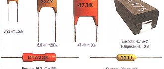
To establish the value of an SMD capacitor, you will need to carefully study its markings. On large-sized elements, as a rule, basic information is applied not only about its denomination, but also the manufacturer’s logo is indicated.
When figuring out the parameters of small bricks, you will have to spend a certain amount of time, because even if the necessary information is available on their body, it is unlikely that you will be able to see the symbols on their surface with the naked eye.
Important! Depending on the type of capacitor, the designations of its parameters may also differ significantly, which must be taken into account in the work
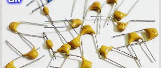
Marking of ceramic SMD capacitors
Small ceramic SMD capacitors are marked with an alphanumeric code consisting of 3 characters. The first indicates the minimum operating temperature, for example:
- Z - from 10 °C;
- Y - from −30 °С;
- X - from 55 °C.
Marking of SMD capacitors
The second symbol indicates the upper limit of heating of the radio component:
- 2 - up to 45 °C;
- 4 - up to 65 °C;
- 5 - up to 85 °C;
- 6 - up to 105 °C;
- 7 - up to 125 °C;
- 8 - up to 150 °C;
- 9 - up to 200 °C.
The third character indicates the accuracy of the electronic component:
- A - up to ± 1.0%;
- B - up to ± 1.5%;
- C - up to ± 2.2%;
- D - up to ± 3.3%;
- E - up to ± 4.7%;
- F - up to ± 7.5%;
- P - up to ± 10%;
- R - up to ± 15%;
- S - up to ± 22%;
- T - up to ± 33%;
- U - up to ± 56%;
- V - up to ± 82%.
The capacity of small ceramic SMD capacitors is indicated in picofarads. To save the area of a small radio element, the main mantissa number is encoded in a letter of the Latin alphabet. The table below provides a complete list of such designations.
Table with encoded charactersAfter the number, the multiplier is indicated, for example, the designation on a ceramic capacitor X3 means that the capacitor has a capacity of 7.5 * 10 ^ 3 Pf.
Note! The code indicating the capacity of a ceramic SMD capacitor may be preceded by a Latin letter, which indicates the brand of the manufacturer of the electronic component. If the area of this type of ceramic capacitor is large enough, then the dielectric type can be displayed on it
For this purpose the following are used:
If the area of this type of ceramic capacitor is large enough, then the dielectric type can be displayed on it. For this purpose the following are used:
- NP0. The dielectric constant of such an element is at an extremely low level. The main advantage of components of this type is their good resistance to sudden temperature changes. The disadvantage of elements that use this type of dielectric is their high price;
- X7R. Average quality dielectric. Products that use this type of insulator do not have excellent breakdown resistance characteristics, but in the average temperature range they are able to work significantly longer than many more expensive elements;
- Z5U. A dielectric with high electrical permeability values, but the downside of this indicator is that the capacitance error is too large;
- Y5V. The insulating material has approximately the same characteristics as Z5U. In terms of cost, this dielectric is the cheapest, so electrical components made on its basis are sold at the lowest prices.
Burnt SMD capacitor
Considering all of the above, you can be sure that if the SMD capacitor has not burned or changed the color of the surface for other reasons, then you can always determine its value by the markings on its body.
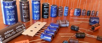
Marking of electrolytic SMD capacitors
Electrolytic capacitors of this type, as a rule, are relatively large in size, so many parameters of such elements are indicated without encryption. That is, the maximum voltage value will be indicated by the number and letter “V”, and the capacitance will be mF.
Marking of electrolytic SMD capacitors
In some cases, the SMD value of an electrolytic type capacitor may also be encoded. Typically, 4 characters (one letter and 3 numbers) are used for this purpose. The first character is the voltage in volts:
- e 2.5;
- G 4;
- J 6.3;
- A 10;
- C 16;
- D 20;
- E 25;
- V 35;
- H 50.
Note! The next three digits encode information about the capacitance of the capacitor (2 digits + multiplier). Thus, even very small-sized electrolytic SMD capacitors can be marked with information about the main parameters of the product
Thus, even very small electrolytic SMD capacitors can be marked with information about the main parameters of the product.
Tantalum contributed to progress
Since the very beginning of radio electronics, research has been carried out that was aimed at reducing the size of structural elements. The main direction in this matter is to increase the operating frequency of the signal. If we compare two power transformers with operating frequencies of 50 and 400 Hz, the second one is approximately 8 times smaller in size than the first.
Older capacitor designs consist of rolled up rolls of thin aluminum foil that are placed in an electrolyte. Achieving a large capacity was possible only by increasing the size of the element itself. Another disadvantage of this design is the large parasitic inductance when operating at frequencies of 100 kHz and above.
A breakthrough in the production of large capacity and small capacitors was achieved using tantalum. This rare earth metal is more expensive than gold and its extraction is quite difficult, but very little of it is required to make one element - no more than a few micrograms. Gradually, tantalum electrolytic capacitors replaced the obsolete ones based on aluminum foil, as their production improved and the cost became quite low.
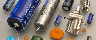
What are SMD capacitors and what are they for?
Many electronic components are large in size and are mounted on the board using wire taps or wide legs, similar to microcircuits. For reliable fixation, the contact elements of such parts are installed in specially made holes, in which they are coated with molten solder to ensure high-quality electrical contact.
Standard installation of radio components
If the power dissipation of resistors or the value of capacitors is too small, then there is no need to make such a product too bulky. Installing elements of this type by drilling the board would force electronic circuit designers to allocate an unreasonably large area of the printed circuit for their installation. The logical solution to this problem is to use SMD components.
SMD technology (Surface Mounted Device) is a method of installing electronic parts without drilling the board. Such a component is simply soldered on one side of the surface, thereby saving significant area without reducing its strength by the presence of a large number of micro-holes.
Note! The surface mounting method can be used to install not only capacitors, but also resistors, transistors and microcircuits. The use of SMD components allows for maximum optimization of the arrangement of parts on the board
Thanks to the use of this technology, circuits for complex devices can be manufactured in relatively small sizes, which is especially important when designing mobile products
The use of SMD components allows for maximum optimization of the arrangement of parts on the board. Thanks to the use of this technology, circuits for complex devices can be manufactured in relatively small sizes, which is especially important when designing mobile products.
Introduction
The modern radio amateur now has access to not only ordinary components with leads, but also such small, dark parts that you can’t understand what’s written on them. They are called "SMD". In Russian this means “surface mount components”. Their main advantage is that they allow the industry to assemble boards using robots that quickly place SMD components in their places on the printed circuit boards, and then mass bake them to produce assembled printed circuit boards. The human share remains with those operations that the robot cannot perform. Not yet.
The use of chip components in amateur radio practice is also possible, even necessary, as it allows you to reduce the weight, size and cost of the finished product. Moreover, you practically won’t have to drill.
For those who first encountered SMD components, confusion is natural. How to understand their diversity: where is the resistor, and where is the capacitor or transistor, what sizes do they come in, what types of SMD parts are there? You will find answers to all these questions below. Read it, it will come in handy!
How to find out where the polarity of a capacitor is
Most elements have a more or less uniform polarity marking system. The capacitor polarity designation has several types that are easy to remember:
- Appearance (body shape, length and thickness of legs);
- Marking (applying appropriate symbols at the terminals or on the body);
- Designations on electronic circuits.
By appearance
How to determine the polarity of a capacitor by appearance? This is easiest to do for devices with a cylindrical body, in which the leads are located at opposite ends (axial type of body). Even if the marking is completely erased, the terminal that is connected directly to the metal case has a minus sign.
The terminal installed on the housing through an insulator (in this place there is usually a thickening or change in the shape of the housing) corresponds to positive polarity, that is, “plus”.
Axial body shape
Newer, non-welded types of aluminum designs with legs located in close proximity to each other (radial body) have a longer positive lead.
Sometimes in old equipment you can find electrolytic capacitors with one terminal, which are attached to the body of the structure with a nut. Here the nut is “minus”, the terminal is “plus”.
Nut fastening
Even more rarely, you come across elements with a nut fastening, but with two terminals. The principle of marking is in many ways similar to the previous case, but here we are dealing with a dual capacitor, in which the common “minus” is located on the body, and the “plus” is located on the terminals (each terminal corresponds to a separate capacitance).
By labeling
Manufacturers also apply markings on the body of the elements. There may be several options here:
- The minus sign is on the side surface of the cylinder from the negative terminal side;
- The plus sign is directly at the positive leg of the element;
- A wide dark stripe at the end opposite the negative terminal (usually on solid-state electrolytic capacitors.
Note! For SMD components, the designation is the opposite - a wide light or dark stripe near the positive pad. Marking of solid-state and SMD components
Marking of solid-state and SMD components
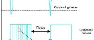
According to the scheme
On electrical diagrams, capacitors are indicated in the form of two parallel lines, which symbolize the plates. A “+” symbol is placed near the positive terminal, or this terminal is indicated by a thicker line, or in the form of a narrow rectangle.
Some electronics manufacturers draw the negative terminal in the form of an arc segment on the diagrams.
Designation on circuit diagrams
On printed circuit boards, an electrolytic capacitor has the following polarity designations:
- As in electrical circuit diagrams;
- In the form of a circle, in which a narrow segment is painted over at the place where the negative terminal is soldered.
Electrolytic
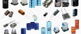
These surface mount components consist of:
- Aluminum cylindrical body, with a diameter from 4 to 10 mm and a height from 5.4 to 10.5 mm;
- Two sheets of thin foil, separated by paper soaked in electrolyte and rolled into a small roll;
- Two contacts (terminals) that are perpendicular to the centerline of the component. Since electrolytic SMD drives are polar, a negative potential is connected to one of the contacts, indicated by a special strip at the end of the case, and a positive potential is connected to the second.
- A mounting pad designed to secure a component to a work surface.
Various models of these components, rated from 1 to 1000-150 μF, are capable of operating at voltages from 4 to 1000 V.
Passive components: Electrolytic capacitors
| TYPE: | Type Explanation: | ||||
| S.E. | Aluminum Capacitor Aluminum capacitor (polar component) | ||||
| Case diameter | Case height | Tape width | Component pitch in the ribbon | Qty per standard package (180 mm/7 inches) plastic tape | Qty per standard pack (330 mm/13 inches) plastic tape |
| 3 mm | 5.5 mm | 12 mm | 8 mm | 100 | 2000 |
| 4 mm | 5.5 mm | 12 mm | 8 mm | 100 | 2000 |
| 5 mm | 5.5 mm | 12 mm | 12 mm | 100 | 1000 |
| 6.3 mm | 5.5 mm | 16 mm | 12 mm | 100 | 1000 |
| 8 mm | 6 mm | 16 mm | 12 mm | 100 | 1000 |
| 8 mm | 10 mm | 24 mm | 16 mm | 100 | 500 |
| 10 mm | 10 mm | 24 mm | 16 mm | 100 | 300 — 500 |
| 10 mm | 14 - 22 mm | 32 mm | 20 mm | — | 250 — 300 |
| 12.5 mm | 14 mm | 32 mm | 24 mm | — | 200 — 250 |
| 12.5 mm | 17 mm | 32 mm | 24 mm | — | 150 — 200 |
| 12.5 mm | 22 mm | 32 mm | 24 mm | — | 125 — 150 |
| 16 mm | 17 mm | 44 mm | 28 mm | — | 125 — 150 |
| 16 mm | 22 mm | 44 mm | 28 mm | — | 75 — 100 |
| 18 mm | 17 mm | 44 mm | 32 mm | — | 125 — 150 |
| 18 mm | 22 mm | 44 mm | 32 mm | — | 75 — 100 |
| 20 mm | 17 mm | 44 mm | 36 mm | — | 50 |
Marking of SMD capacitors - Technopolis tomorrow
(The lion's share of information was borrowed from the portal https://kazus.ru)
Marking of ceramic SMD capacitors
Due to their small size, SMD ceramic capacitors are sometimes marked with a code consisting of one or two characters and a number. The first character, if any, is the manufacturer's code (eg K for Kemet, etc.), the second character is the mantissa and the digit exponent (multiplier) of the capacitance in pF. For example S3 is a 4.7nF (4.7 x 10³ Pf) capacitor from an unknown manufacturer, while KA2 is a 100 pF (1.0 x 10² PF) capacitor from Kemet.
| Letter | Mantissa | Letter | Mantissa | Letter | Mantissa | Letter | Mantissa |
| A | 1.0 | J | 2.2 | S | 4.7 | a | 2.5 |
| B | 1.1 | K | 2.4 | T | 5.1 | b | 3.5 |
| C | 1.2 | L | 2.7 | U | 5.6 | d | 4.0 |
| D | 1.3 | M | 3.0 | V | 6.2 | e | 4.5 |
| E | 1.5 | N | 3.3 | W | 6.8 | f | 5.0 |
| F | 1.6 | P | 3.6 | X | 7.5 | m | 6.0 |
| G | 1.8 | Q | 3.9 | Y | 8.2 | n | 7.0 |
| H | 2.0 | R | 4.3 | Z | 9.1 | t | 8.0 |
Capacitors are manufactured with different types of dielectrics: NP0, X7R, Z5U and Y5V…. The NP0(COG) dielectric has a low dielectric constant, but good temperature stability (TKE is close to zero). SMD capacitors of large ratings made using this dielectric are the most expensive. X7R dielectric has a higher dielectric constant, but lower temperature stability. Dielectrics Z5U and Y5V have a very high dielectric constant, which makes it possible to produce capacitors with a large capacitance value, but with a significant spread in parameters. SMD capacitors with X7R and Z5U dielectrics are used in general purpose circuits.
| +10°C | 2 | +45°C | A | ±1.0% | |
| Y | -30°C | 4 | +65°C | B | ±1.5% |
| X | -55°C | 5 | +85°C | C | ±2.2% |
| 6 | +105°C | D | ±3.3% | ||
| 7 | +125°C | E | ±4.7% | ||
| 8 | +150°C | F | ±7.5% | ||
| 9 | +200°C | P | ±10% | ||
| R | ±15% | ||||
| S | ±22% | ||||
| T | +22,-33% | ||||
| U | +22,-56% | ||||
| V | +22,-82% |
Examples:
Z5U is a capacitor with an accuracy of +22, -56% in the temperature range from +10 to +85°C.
X7R is a capacitor with ±15% accuracy over a temperature range of -55 to +125°C.
Marking of electrolytic SMD capacitors
The following coding principles are used by such well-known companies as PANASONIC, HITACHI, etc. There are three main coding methods.
A. The code contains two or three characters (letters or numbers) indicating the operating voltage and rated capacity. Moreover, the letters indicate voltage and capacitance, and the number indicates the multiplier. In the case of a two-digit designation, the operating voltage code is not indicated.
B. The code contains four characters (letters and numbers) indicating the rated capacity and operating voltage. The letter at the beginning indicates the operating voltage, subsequent characters indicate the capacitance in picofarads (pf), and the last digit indicates the number of zeros.
There are 2 options for capacity coding:
- the first two digits indicate the nominal value in pF, the third - the number of zeros;
- Capacitance is indicated in microfarads, the p sign acts as a decimal point.
Below are examples of marking capacitors with a capacity of 4.7 μF and an operating voltage of 10 V.
C. If the size of the case allows, then the code is located in two lines: the capacitance rating is indicated on the top line, and the operating voltage is indicated on the second line. Capacitance can be indicated directly in microfarads (uF) or 8 picofarads (pf) indicating the number of zeros (see method B). For example, the first line is 15, the second line is 35V means that the capacitor has a capacity of 15 uF and an operating voltage of 35 V.
Marking of tantalum SMD capacitors
The marking of tantalum capacitors in sizes A and B consists of a letter code for the rated voltage according to the following table:
| Letter | G | J | A | C | D | E | V | T |
| Voltage, V | 4 | 6.3 | 10 | 16 | 20 | 25 | 35 | 50 |
It is followed by a three-digit code for the capacitance rating in pF, in which the last digit indicates the number of zeros in the rating. For example, the marking E105 indicates a capacitor with a capacity of 1,000,000pF = 1.0uF with an operating voltage of 25V.
The capacity and operating voltage of tantalum SMD capacitors of sizes C, D, E are indicated by their direct notation, for example 47 6V - 47uF 6V.
Code and color marking of capacitors
Code and color marking of resistors
Universal color chart
For a detailed study of this technique, you can consider the domestic GOST 175-72. According to the current rules, each color corresponds to a certain number. Silver and gold represent decimal parts.
Using a universal table, color codes are deciphered
The figure shows an example of a specialized program. With the help of such calculators, determining the denomination is simplified. The calculation is performed automatically. To find out the value in digital form, just make marks in accordance with the color of a specific radio component.
Standard series of denominations
In order to select serial products without errors, it is worth recalling the use of special row designations. For E12, for example, the permitted deviation from the nominal value is no more than 10% upward/downward. Standard values (15; 18; 22 and others) are calculated in such a way as to eliminate errors with maximum error. The difference between adjacent positions must be 200% or more compared to the established tolerance.
Errors for other rows “E” are given in the following list (%):
- 192 (0,5);
- 96 (1);
- 48 (2);
- 24 (5);
- 6 (20).
For your information. Products with a minimum deviation from the nominal value of electrical resistance are marked with three significant rings (numbers). Additional bars indicate a multiplier and a certain tolerance.
How to determine the rating and voltage
Many manufacturers do not indicate on their products such basic characteristics for any capacitor as operating voltage and rating (nominal capacity).
Tantalum capacitors
The rating of these electronic components is determined in the following ways:
Using a measuring instrument such as a multimeter that has the function of measuring the nominal value. To measure the nominal value, the control probes of the device are connected to special connectors. Then the switch is set to the largest measurement limit (in most multimeters this is 200 µF). After this, the probes are applied to the contacts of the capacitor; after a few seconds, the value of the storage device’s rating is shown on the device’s display.
Important! Before measuring the capacitance, the SMD drive must be discharged - the charge remaining in the plates can damage the electronic circuits of the multimeter. Using a specialized RLC measuring instrument
Using a specialized RLC measuring device.
In order to find out the operating voltage of an SMD storage device, use the following simple method:
- Using a multimeter, measure the voltage between the terminals of the component included in the circuit;
- The resulting value is multiplied by 1.5.
The operating voltage calculated in this way will be approximate; a more accurate value of this characteristic can be found from the marking code of the capacitor or its description.
Video
Capacitors for starting an electric motor
XXI CENTURY Candy Fudge Scented water
266 ₽ More details
Ponty Perfume Lily Fragrant water
175 ₽ More details
Men's flip-flops
Main characteristics
KM capacitors are ceramic monolithic capacitors in cased and uncased versions. They belong to a subclass of constant capacitors. According to the classification, these are low-voltage capacitors with voltages up to 1600 V. The capacitance range is from 16 pF to 2.2 μF. Is it a lot or a little? For comparison, let's say that the Earth's capacitance is about 710 microfarads.
The KM group of low-voltage capacitors is divided into low-frequency and high-frequency. According to their purpose, they are divided into three groups: 1, 2 and 3.
— group 1 is used when high capacity stability and low losses are essential; - group 2 - when what is characteristic of group 1 is not essential; - group 3 - like the second group, but is intended for operation in low-frequency circuits.
There are more than ten basic electrical parameters for each capacitor and more than 25 performance characteristics. We emphasize that these are only the main ones; the full list is close to 60. Let's look at some of them.
Nominal capacity. This value is standardized and selected from a certain series - E3, E6, E12, E24, E48, E96, E192. For each decimal interval, the numbers after E indicate the number of nominal values. So, for example, for E6 we have a number of nominal capacity values: 1.0 1.5 2.2 3.3 4.7 6.8 (for each decimal interval).
For nominal values there is a limit of permissible deviations, which is expressed as a percentage. For example: ±0.1%, ±0.25%, … ±30%, (-10+30)%, (-20+50)%.
Rated voltage. This is the voltage at which the capacitor can operate under certain conditions and maintain its parameters within acceptable limits. For KM capacitors, depending on the modification, the range of values lies from 25V to 250V.
Temperature coefficient of capacity (TKE). It is used for capacitors with a linear dependence of capacitance on temperature.
TKE value: using this parameter, you can determine how much the capacitance of the capacitor will change if the ambient temperature changes by one degree in a given temperature range (both Celsius and Kelvin scales are used). A number of TKE KM capacitors: P33, MPO, M47, M75, M750, M1500, N30, N50, N90.
Conclusion
As a result of this lesson, I no longer just point out X7R or X5R types to colleagues or suppliers. Instead, I list specific batches from specific suppliers that I have tested myself. I also caution clients to double-check specifications when considering alternative manufacturing suppliers to ensure they do not encounter these problems. The main conclusion from this whole story, as you probably guessed, is: “read the datasheets!” Always. With no exceptions. Request additional information if the datasheet does not contain sufficient information. Remember that the designations for ceramic capacitors are X7V, Y5V, etc. They say absolutely nothing about their voltage coefficients. Engineers must double-check the data to know, really know, how the capacitors they use will perform under real-world conditions. So keep in mind, in our mad rush to get smaller and smaller, this is becoming more and more important every day.