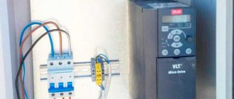
An automatic two-pole switch for protecting the electrical network structurally includes 2 single-pole circuit breakers with a common switch lever and an internal locking system. In this material we will talk in detail about what a two-pole circuit breaker is, what are the features of its operation and installation, and we will also understand what the main difference between two-pole circuits and single-pole protective devices is.
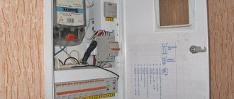
Installing a circuit breaker in the panel
Now about the installation itself.
The body of the machine has a switching marking - that is, the question of where to screw the phase is not worth it, how to connect the circuit breaker to the network - is drawn on the machine. Before installation, we unscrew the bolts of the contact group, measure the entry depth (the length of the stripped part of the cable), and check the presence of threaded fasteners on the DIN rail (some models have a hole at the bottom that allows you to further strengthen the device on the rail using a screw).
The procedure for installing a circuit breaker begins with “trying on”. We place all the machines on the latches along the rail, evaluate the distances between them, the availability of space for additional ones (if necessary), as well as the possibility of marking the connections. We mark all the conductors separately (regardless of color), phase, neutral, ground, and then strip the cables.
We strip the cables in the panel where the machines are located on the rail. This is done in order to accurately estimate the required length of wires.
We check the quality of the ground-zero wire contact. Ideally, the distance from each neutral wire to the ground cable should be approximately the same. That is, 10 and 20 cm are the same, but 20 cm and a meter are unacceptable. PEUs give a spread of up to 60%
. That is, the shortest entrance is 10 cm, if the longest is 60 cm. This is what we focus on.
We make sure that the circuit breaker connection diagram is correct, the “layout” is correct, everything is ready for installation. We turn on the first circuit breaker without fixing it, but after extending the wires, check the switching and check the line
We check simply: carefully insert nails into the socket using insulated pliers. Then we drop another nail across
If everything is done correctly, the machine will disconnect the line. In order to avoid “welding the nail”, it is better to throw it in a big way. It will shorten if something goes wrong, but the nail will bounce off - inertia will not allow welding and the electrical wiring will not be damaged.
Having checked the line in this way (if you are planning to connect and install everything yourself, one machine is enough, you do the rest in exactly the same way), you can finish the process.
More modern analogues of the device
The old package switches have been replaced almost everywhere with automatic machines. This is logical, because the requirements for energy consumption and durability of devices have changed. Nowadays, RCDs (residual current devices), automatic and differential circuit breakers, and contactors are widely used.
Option #1: residual current device
The device is designed to prevent current leaks. It reacts to differential current, which contributes to overheating of electrical cables, which can lead to a short circuit and fire of the wiring. Leaks can also cause electric shock to a person.
The device cannot be considered a 100% analogue of a bagger, however, when combined with a circuit breaker, it performs even more functions
An RCD must be installed to avoid the risk of electric current leakage if it begins to pass by consumer devices. The device functions as a leak indicator, which simply turns off the electricity in case of problems.
The residual current device itself does not protect against overloads or short circuits. This is only possible if it is connected in combination with a circuit breaker.
Option #2: circuit breaker
These devices replaced the batch switch. They perform the same functions, but are more convenient to use, durable and wear-resistant.
Automatic switches can also be one-, two-, three-, four-pole. They differ in the type of drive (it can be manual, spring, motor), type of connection and other technical and operational characteristics.
A selective circuit breaker does not require additional power to make or open its contacts. The device is electro-mechanical and is designed to perform its functions in the best possible way.
Circuit breakers offered for sale are marked and classified in accordance with GOSTs 9098–78 and 14255. These documents establish requirements for the technical characteristics of devices.
Option #3: differential machine
This is a combined machine that simultaneously performs the functions of two devices - an RCD and a circuit breaker. The differential automatic machine perfectly replaces the packetizer, is suitable for household electrical networks and is successfully used in enterprises.
Differential circuit breaker is a “2 in 1” device: a circuit breaker and an RCD located in a common housing. It flawlessly copes with the tasks of both devices and at the same time is compact and easy to use.
The functional and design differences between the diffavtomat and the RCD are given here; we recommend that you familiarize yourself with the very useful information.
The differential circuit breaker prevents leaks, short circuits, and minimizes the risk of electric shock. The design of the device includes thermal and electromagnetic releases. The first prevents overloads in the network, and the second is needed to turn off the electric current in the event of a short circuit.
Option #4: contactor - a type of electromagnetic relay
The device is necessary for remote control of on/off modes of electrical circuits. Electromagnetic relays do not operate in the event of a short circuit and are designed for rated currents only. This is their main difference from circuit breakers.
The devices are characterized by exceptional electrical and mechanical wear resistance. They are installed in the mechanisms of elevators, vehicles, and used in enterprises
In modern residential buildings, outdated package switches are rarely installed. Almost everywhere it is practiced to install automatic circuit breakers or connect an RCD in combination with a circuit breaker. But there are cases when a good old bag can be indispensable, for example, if you need to turn off the current supply during electrical installation work.
Selection mistakes to consider
Finally, let's look at the most common mistakes that are made when choosing a circuit breaker.
Error 1.
When choosing an automatic machine, they are guided by the total power of consumers, which is one of the most serious mistakes.
The machine only protects the wiring from overloads; it is unable to change its characteristics.
If you place a powerful machine on weak wiring and connect a strong energy consumer to it, this will inevitably lead to damage to the wiring, and the machine will not be able to do its job.
Therefore, you should always focus on the cross-section of the wire and its throughput, and not on the power of the consumers.
Error 2.
Often, all branches of the network are equipped with the same machines, and then they try to use one of the branches as a heavily loaded one.
Even at the stage of installation of the electrical network, it is advisable to ensure that at least one of the branches has increased parameters and is equipped with a circuit breaker designed for significant loads.
For example, in the garage of a private house, it is possible to use devices that create a significant load.
It is better to strengthen this branch in advance than to redo it later or hope that the machine or wiring will “stand.”
Error 3.
When purchasing circuit breakers, buyers try to minimize costs. It's better not to skimp on safety.
You should buy such devices only from well-established companies in specialized stores, and even better from an official distributor.
We hope that the tips above will help you choose the right circuit breaker for your home.
Connecting a two-pole circuit breaker
Before connecting the circuit breaker, you need to understand the purpose of this device, its functions and capabilities. An automatic two-pole switch is, by and large, two single-pole circuit breakers assembled in a single housing. According to the PUE, it is impossible to disconnect only one phase wire or a neutral wire in order to ensure the safe operation of electrical installations. This device has several protections:
- From a short circuit, that is, from a sharp increase in large currents that arise in the circuit;
- From a long-term increase in current above the rated current, by a given and clearly advertised amount.
That is, the machine will turn off emergencyly if, for example, it is designed for a working current equal to 20 A, and for 20 minutes, for example, 25 A will flow through it; a thermal relay will operate in it, which may prevent it from being turned on again. Only after the circuit breaker, or rather its thermal relay, has cooled down to operating temperature will it be possible to turn it on again. The machine will also turn off if a short circuit occurs in the outgoing circuit, that is, the one that went to consumers.
To connect the switch, you first need to decide on the energy source, that is, where it will be powered from. The installation of automatic switches in the panel will be carried out in any case, also from a machine only with a higher rating.
The source to which you can connect the upper contacts of the machine is known; now you need to decide whether it will withstand all the loads and all the consumers that will be connected. Each electrical device has its own ratings:
- Power consumption;
- Voltage;
- Current strength.
Read more: LED lamps ASD purpose, types of light bulbs and opinion about the product
Each is important, but sometimes some appliances may only list wattage and voltage. You can determine the approximate current strength yourself; to do this, the power of the electrical appliance must be divided by its operating voltage. The power supply should be selected according to the sum of all devices that will be connected to it.
For example, if there are three electrical devices that will consume 5 A each during their operation, then the circuit breaker should have a little margin of 20–25 A. Then the flowing operating current will be equal to 15 Amperes, with the operating current of the machine being 25. All devices will operate normally, without overheating.
And in emergency situations, the entire circuit will be immediately turned off, thereby ensuring reliable fire safety of the room. Polarity in AC voltage circuits does not matter, so it makes no difference which terminals the phase will be connected to and which the zero will be connected to. In DC circuits, double-pole switches are also often used. One of the terminals is negative, the other is positive, but in everyday life constant voltage is used very rarely.
How to choose a two-terminal network
To choose a good protective device, you should focus on the cross-sectional area of the connection wire. To do this you will need to calculate the value.
First, you should calculate the power and current of the equipment on the power line from the machine. For the current in the circuit, the formula I=P/220 is used, where 220 is the rated voltage, I is the current (A), P is the power (W).
Next, select the wire type based on the table.
| Current strength, A | Network power, W | Copper wire cross section | Aluminum wire cross section |
| 1 | 0,2 | 1 | 2,5 |
| 2 | 0,4 | 1 | 2,5 |
| 3 | 0,7 | 1 | 2,5 |
| 4 | 0,9 | 1 | 2,5 |
| 5 | 1,1 | 1 | 2,5 |
| 6 | 1,3 | 1 | 2,5 |
| 8 | 1,7 | 1 | 2,5 |
| 10 | 2,2 | 1,5 | 2,5 |
| 16 | 3,5 | 1,5 | 4 |
| 20 | 4,4 | 2,5 | 6 |
Based on the data obtained, you can select a machine taking into account thermal inertia during heating.
The current in the wires must be greater than the current of the difavtomat, and the latter must be greater than the current load.
Installation details of switches
For all electrical devices of this design, the order of implementation into the electrical circuit is determined.
Installation of circuit breakers is, at first glance, a technically simple procedure. However, if you take into account exactly all the existing installation rules, the installation process of machines can be compared to the work of creating computer software
The established procedure, in particular, requires the following actions by installers before two-pole and three-pole switches are installed:
- the device must correspond to the design for the current circuit;
- the machine body is free from deformation and damage;
- The on/off lever works clearly in manual activation mode.
The base on which the device is supposed to be installed must be checked for evenness of the surface. Installation on bases where, due to the uneven surface after mounting, the machine body is subject to bending stresses is not allowed.
Connection to network conductors
The connection of copper conductors with a cross-section of 16 - 25 mm2 is carried out through cable lugs (GOST 9688-82). If it is necessary to make a connection with copper conductors with a cross-section of 4 - 16 mm2, cable lugs of a different type are used (GOST 7386-80).
In relation to connections of aluminum wires, end elements similar to TAM-7 are used, corresponding to the parameters of GOST 9581-80.
Tips of conductors supplied to the contact terminals of automatic machines. Often this point is ignored; the conductors are simply twisted and connected to the device in this state. In fact, this approach is already considered a violation. The exception is wires with a cross section of less than 4 mm
The network conductors supplying voltage from the power source are connected to the upper group of fixed contacts of the circuit breakers. It is necessary to supply and connect conductors so that they do not create forces on the terminals of the machine.
The tips should be tightened tightly with the contact clamps, but without extreme forces that could lead to thread breakage
The termination of conductors in cable lugs should be given great care. Be sure to use insulating tubes and tape as a protective sheath
Nuances of placement and fastening
When installing several pieces of equipment, it is necessary to follow the rules for arranging the devices relative to each other. Thus, the distance between closely located devices should be maintained at least 5 mm.
Installation of switches in a group. It looks quite nice and neat. Meanwhile, in this case, the installation process is carried out with errors. According to regulations, when installed in a group, the distance between the walls of adjacent devices must be at least 5 mm
Minimum distances from metal parts of switchgears: from above 30 - 50 mm, from the side 5 - 10 mm, depending on the magnitude of the supplied voltage.
If the installation uses devices that are structurally made in an additional shell, all installation manipulations with them are carried out with the shell cover removed. The installation of the cover is carried out taking into account the correct insertion of the drive mechanism. The cover is fastened with screws evenly.
Upon completion of installation, the machines must be checked for clarity of the moment of switching on/off.
Wiring diagrams and rules for connecting the switch are described in detail in this article.
Difference between double-pole and single-pole circuit breaker
The difference between a single-pole and a double-pole switch is that the first monitors the technical parameters of several lines. Accordingly, the difference between two and three-pole is that in the first two lines are monitored, and in the second - three lines. When the voltage in one is exceeded, the device protects each line. The second device protects only one power line. At the same time, it is impossible to replace a two-pole circuit breaker with several single-pole ones due to the shutdown lever. The interlock is designed so that if there is a problem, both lines will be disconnected. In addition, the current will not evaporate. It will penetrate into a properly working device and a fire may occur.
Difference between double-pole and single-pole circuit breaker
Advantages and disadvantages
The advantages include reliable protection, the ability to control power, and ease of installation and maintenance. The main advantage is the de-energization of several conductors, regardless of the occurrence of an accident in any of them. Thanks to this, tension is completely removed.
You might be interested in: Installation of an electric meter
The disadvantages of a multi-pole protective device are the possibility of cable breakdown by electric current during a simultaneous short circuit of several electrical networks.
Note! They also include turning off the power to the electrical wiring during a breakdown of the thermal release, the inability to turn on the power after an emergency line breakdown and sensitivity to mechanical damage
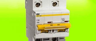
Specifications
Technical characteristics of two-pole circuit breakers vary depending on price and manufacturer. The rated voltage is 240 watts, the rated current is from 6 to 63 amperes, the number of poles is from 1 to 4, the time-current characteristic is designated B, C and D.
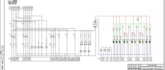
Technical characteristics of electrical equipment
Installation and connection diagrams
A two-pole circuit breaker is installed according to the electrification plan. The housing is checked for damage and deformation before installation. The operation of the shutdown handle must be of high quality. During installation, the connection of a copper conductor using a lug and the connection of an aluminum cable using an end piece are taken into account. The upper group of stationary circuit breakers, conductor sealing with insulating tubes and protective tape, the distance of nodes and the location of the additional box are also taken into account.
The machine is placed on part of the DIN rail. The latch bracket is removed using a flat-head screwdriver and placed on the rail with fasteners. During installation, the usual scheme is used. An input switch is placed before the meter, after it a two-pole type device is mounted, and a neutral with a phase is connected on top. The cores are routed from below to the circuit. Wired copper jumpers are used to connect multiple devices together. The end is cleaned using a sharp object and crimped using a crimper.
Note! During installation of the device, work must be carried out by two specialists wearing protective rubber gloves after obtaining permission from the housing and communal services. The connection must be made to the panel without damage at the mounting location
Features of DAV
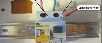
A special feature of the DAV is that it must break the electrical circuit when the permissible current in any of the supply wires is exceeded. Such a machine has 4 terminals, and the releases in it are triggered when the current regime is disrupted in both the phase wire (L) and the neutral wire (N).
Rice. 2. Two standard OAVs cannot replace DAVs
Therefore, two standard OAVs cannot replace DAVs. When the latter is triggered, both connected lines are de-energized simultaneously. If two single-pole AVs are used, then in this case one circuit will turn off, and the second can continue to work. And such an imbalance in some cases can lead to dangerous consequences, for example, during repair work.
Multi-position switches of modular type
The cam burst switch is the most common type of these devices, like other switches, it is used to control various types of electrical loads.
Cam switches
The scope of application of cam switches is quite extensive; here are some examples of their use:
- AC and DC control switchboards;
- emergency shutdown systems, automatic transfer of reserve, switching of operating modes of electric motors;
- control of transformer substations and lighting;
- equipment for substations (control of grounding switches, sectional switches, disconnectors, etc.);
- switching heating equipment modes (turning on, off, switching electric heating elements of the load);
- selection of operating mode of electric welding equipment, etc.
Cam switches consist of several packages (each responsible for switching one line) placed in one housing. The figure below shows the structure of such a package.
Cam Switch Package
Designations in the figure:
- a - fixed contacts (4 pcs.), to which wires are connected;
- b – a special protrusion “cam”, which allows you to hold and move the rod;
- c – group of movable contacts (there are two of them in this type);
- d – two guide grooves (allow the rod to make translational movements);
- e – two rods covered with an insulating shell;
- f – contacts (8 pcs.), usually made of an alloy containing silver;
- g – package;
- h – two threaded rods (fix the bag and the lid);
- I – rotor;
- J – four springs (return the rod to the closed position);
- k - shaft connecting the handle to the rotor;
- l – four screws for clamping cable wires.
Note that the batch switch (cam switch) can have several positions, including zero, that is, when the contacts are disconnected. The figure shows the state of the switch in the neutral position.
Schematic representation of the switch in the zero position
ABB switch in zero position mode
Note that all the main characteristics of the switches are indicated on the device case; the following are displayed there:
- switch type;
- rated current for which the switch is designed;
- switching diagram and table;
- protection class.
Below is a diagram and switching table shown on the housing of the SPAMEL rotation direction switch.
Scheme and switching table of the SPAMEL switch
Thanks to this table, you can clearly see in what position and which groups of contacts are connected.
The difference between two-pole machines
The greatest difference between such machines and single-pole ones is that the latter monitor the parameters of both lines simultaneously and guarantee that both are turned off when the current parameters change significantly, while a pole circuit breaker controls only one line.
It is impossible to make an equivalent replacement of a two-pole circuit breaker with two single-pole ones, because the two-pole ones have in their design not only a common shutdown lever, but also a special locking mechanism that allows you to quickly de-energize both lines and quickly find problems that have arisen on any of them.
If you install two single-pole circuit breakers, if a malfunction occurs, only the phase will be disconnected. This will not allow you to turn off the zero at the same time, ensuring the safety of the device, because the zero will continue to flow using the second mechanism, which can lead to breakdown or fire of the device.
Between themselves, two-phase circuit breakers differ in the rated current that can pass through them. For example, a machine with a power of 6A will turn off at a load four times less than 32A. Therefore, a more powerful machine is usually installed on a common apartment network, and options with a power of 5a, 6a and the like are connected separately to household appliances.
Functional purpose
The functional purpose of a two-phase machine is to provide control of independent lines in the event of a malfunction and their simultaneous shutdown, normal performance of service lines, and shutdown in the presence of malfunctions.
Note! Also, the purpose is to monitor networks with direct current, and to use, if it is impossible to connect a single-circuit conductor with short-circuited neutral buses.
Functional purpose of the device
Comments:
Evgen
And I thought that the three-pole one is connected as phase-zero-ground, but it turns out to be like this... Live and learn! Can it be used in a panel for a single-phase network, if three circuits need to be disconnected at once?
Vasiliy
Evgen, why is it needed then? Power all three phases through a single-pole switch and they will turn off at the same time without any problems! And you'll save space on the rack.
Denis
Why can't you use a three-pole switch in a single-phase network? Disconnect phase, neutral and ground at the same time? If you place it, for example, at the input to the panel. It seems to me that this is more correct.
Alex
Denis, why do you need to disconnect the ground at the input? A three-pole switch is only
in a three-phase network, but using it in a single-phase network is possible, but impractical. Just as impractical as disconnecting the ground in the example you gave
Vladimir
Sometimes it’s useful to turn off the zero - when there is a phase imbalance, in villages all the time. But you need to tear up the ground ONLY if there is a split trans, and AFTER it.
Virtual Private Servers
One of the most prominent, in the literal sense of the word, characteristics of a circuit breaker is the characteristic that determines the number of poles of the circuit breaker.
Max
and if you need to disconnect two phases and three-pole zero will work
Leave a comment Cancel reply
How to choose a hidden wiring socket, practical advice.
A few simple rules for choosing sockets and switches
Height and placement of sockets in the kitchen in a modern apartment
Sockets built into the tabletop save desk space and do not spoil the appearance
Technical device
Structurally, difavtomats are made of dielectric material. The rear part has a special mount for installation on a DIN rail. Inside, they consist of a two-pole or four-pole switch and a differential protection module connected in series with it. This module is a differential current transformer through which zero and phase pass, thereby forming the primary winding and the control winding - the secondary winding.
On what principle does a single-pole circuit breaker work?
Circuit breakers, like switching devices, perform the functions of conducting permissible electric current and turning off the power if the rating is exceeded, thereby protecting the electrical network from overload.
The task of a single-pole device is to protect the circuit in one wire. The operation of the device is concentrated on 2 distribution devices - thermal and electromagnetic. When the increased load lasts for a long time, the circuit is disconnected by the first mechanism. If a short circuit occurs, the second distributor immediately stops supplying power.
Thermal protection is performed by a plate made of composite material according to the following principle:
- A current exceeding the permissible level is supplied.
- The bimetal heats up.
- Bends.
- Pushes the lever.
- Turns off the device.
- The plate cools down.
When the condition of the bimetal returns to normal, it returns to its original state and the device can be reconnected. The electromagnetic device includes a coil in the middle of which a core is placed.
Here's the picture:
- A short-circuit current occurs.
- Enters the winding.
- The force created by the electromagnetic field moves the core.
- Disables the device.
During the interaction of physical processes, power contacts are opened, which de-energize the conductor.
A high current intensity creates an electric arc; it is directed into a chamber with parallel metal plates for crushing and complete disintegration. The machine can be turned off by simply turning the knob. Such switches are used in ordinary apartments if only 2 wires are connected to the house. In a barn or small private house, single-pole circuit breakers open the circuit. In apartment buildings there are grounding conductors, which means only a two-terminal network will do.
Areas of application
3-phase circuit breakers are used wherever there is a three-phase power supply. Connecting consumers without these protective devices is a gross violation of the rules for electrical installations. It is pointless to list all examples of the use of three-phase machines. Too many of them. Therefore, below are electrical devices that are protected by three-phase circuit breakers, but to some extent are found in the life of every person:
- street lighting networks;
- three-phase asynchronous motors of elevator equipment;
- input distribution devices of residential buildings;
- protection of engines of children's attractions;
- engines of pumping stations that pump water to residential buildings;
- pumps pumping out sewage water are protected by three-phase circuit breakers.
Three-pole circuit breakers are used everywhere. Their use is mandatory wherever there is a 3-phase power supply. Three-pole protection devices are almost no different from single-pole ones. The differences lie only in the number of protected phases, maximum operating currents and overall dimensions.
When connecting a three-terminal network, it is necessary to take into account its timing characteristics and rated current. These parameters are indicated on the body of the protective device
You should also pay attention to the series of the machine. It is determined based on the conditions of future operation, that is, how often the device will be triggered by a short circuit, how many times a day it will be switched by hand
Marking
Particular attention should be paid to the markings of machines.
There are special markings on the body of the machines:
- Rated current of the device (in amperes).
- Overload current group (operation current range).
- Maximum operating current or short circuit current (in amperes).
- Current limiting class (the higher the class, the higher the response speed during a short circuit).
- Graphic designation or schematic diagram of the device.
- Device series.
- The rated voltage at which the machine must be used.
Installation of circuit breakers
The connection of circuit breakers in the distribution cabinet is carried out in a certain sequence. A cable connected to an external current source is inserted from above, and through the output holes located below, the wiring is routed to its objects, in accordance with the electrical diagram.
At the beginning of installation, the input circuit breaker is connected. If there are several lines in the circuit, isolated from each other, they are separated from the input circuit breaker. Its power must be no less than the total power of the machines connected to separate lines. For this purpose, two- or four-pole devices of group D are selected, resistant to the inclusion of power tools and other powerful equipment.
The most widespread are those suitable for any power supply schemes for apartments and private houses. Modular circuit breakers are installed on a DIN rail and connected by conductors with a current carrying capacity exceeding the operating current of the switch. A more convenient connection of several machines in one row can be done using a special connecting bus. A piece of the required length is cut from it and secured in the terminals. This connection is possible due to the distance between the bus contacts corresponding to the standard width of modular machines. The switch is installed per phase, and the neutral conductor is supplied from the input device directly to the devices.
- A single-pole
switch is used when installing sockets and lighting systems. - A two-pole
circuit breaker is suitable for high-power appliances, such as an electric stove or boiler. In case of overload, it is guaranteed to break the circuit. The connection diagram of such switches is practically no different from single-pole models. For more efficient use, it is recommended to connect them to a separate line. - A three-pole
circuit breaker should be installed only in cases where it is planned to use electrical appliances operating at a voltage of 380 V. In order to eliminate the load, the load is connected in a “triangle” pattern. This connection does not require a neutral conductor, and the consumer is connected to its own switch. - A four-pole
circuit breaker is most often used as an input circuit breaker. The main condition for connection is the uniform distribution of the load on all phases. When connecting equipment in a star configuration or three separate single-phase wires, excess current will flow through the neutral conductor.
With all loads evenly distributed, the neutral wire begins to perform a protective function in the event of unexpected power imbalances. To ensure a normal connection, only high-quality materials should be used. All connections must be securely fastened to the terminals. If several cables are connected at once, their contacts must be thoroughly cleaned and tinned.
The procedure for connection can be considered using the example of a two-pole circuit breaker installed in the panel. First of all, the power is turned off to completely de-energize the network. The absence of electricity is checked using an indicator screwdriver or a multimeter. Then the machine must be installed on the DIN rail and snapped into place. The absence of a mounting rail can create certain inconveniences. After this, the cores of the incoming and outgoing wires are stripped to a distance of 8-10 mm.
Input wires are connected to two clamps located on top -. The lower clamps hold similar outgoing conductors distributed to sockets, switches and electrical appliances. All wires are properly clamped into terminals using screws. Connections must be checked manually. To do this, the conductors need to be gently moved from side to side. If the connection is poor, the core will wobble in the terminal and may even jump out of it. In this case, the terminal screw needs to be tightened.
Upon completion of installation, voltage is supplied to the network and the functionality of the circuit breaker is checked.