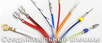
In electrical installation work, one of the most important stages in the work is connecting the equipment. The successful operation of the entire complex of electrical installations at the enterprise depends on the correct execution of all operations at this stage. Before connection, power lines and cables, control circuit wires (secondary switching circuits) are laid. These circuits connect various elements of equipment with a control panel and a protection system. After installation is completed, individual wires and cables are tested before connection. In this article we will tell you why you need to test wires and cables and look at the main methods.
Basic dialing methods
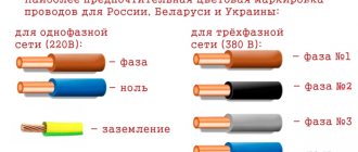
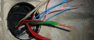
Detection methods depend on the cable brand and location conditions; with colored insulation of the cores, there are no problems. The cable is connected to the equipment according to the color of the cores on both sides. The difficulty arises when the insulation of all or several cores in the cable is the same color, and the cables are not marked. It is in such cases that a test is carried out, the ends on both sides of the cable are determined to belong to the same core, their integrity is determined, and markings are made.
Basic methods and equipment:
- Continuity tester can be performed by one person within one distribution cabinet and at distances of up to 100m;
- A digital multimeter, used in similar conditions, the device is set to continuity or resistance measurement mode.
- A homemade device with a lamp and batteries;
- Telephone handsets with batteries in the circuit.
- A step-down transformer complete with indicator or measuring instruments.
conclusions
When choosing a test kit for testing cables, you should be guided by three main criteria:
- functionality;
- operational characteristics (convenience, reliability, warranty, maintenance);
- price.
Obviously, there is no universal device for testing all types of cables and wires that would be convenient in any situation.
But knowing the assigned tasks, you can choose the ideal tools for their successful implementation. See also:
Main characteristics of tone generators for cable testing
What is better for cable testing: a headset, a handset or a test kit?
Budget LAN tester for twisted pair cables: comparison of 5 popular models!
Wiring continuity tester
Historically, at the initial stage of development of electrical engineering, a tester was called a pointer combined device, which includes:
- Voltmeter;
- Ammeter;
- Ohmmeter.
Then other options were added to modern devices, an electronic thermometer, light and sound indication elements, and controls and application methods were improved. As a result, instead of the old dial tester, it was replaced by its modern analogue, a digital multimeter with a liquid crystal display for displaying readings. One of the functions of the tester is wire continuity testing (checking the integrity of the wire).
Pointer combined device Ts 4342-M1. In order to ring a wire with a pointer tester, you need to carefully study the capabilities of the device, how to connect the measuring probes and in what position to put the switches on the control panel.
Familiarize yourself with the discrete division of the scale; the controls and scales are different on devices of different models. Let's consider the wire testing technique using the example of a pointer tester Ts 4342-M1:
- Set the batch switch of measurement modes to the 1 kOhm position, some models have Ohm.
- Turn on the fuse button, protecting the calibrated elements of the device circuit from incorrect connection. If in continuity mode the circuits are energized.
- Press the forward and reverse current measurement mode buttons, two black buttons at the bottom of the control panel;
- Connect the probe wires to the center and right terminals to measure resistance;
- To check the functionality of the device, connect the probes to each other, the arrow on the scale should move from left to right until it stops. Measurements are carried out on a scale marked kOhm, second from the top. If the arrow moves to the right towards zero, the device is working.
The advantages of this tester are reliable protection and measurement accuracy, but in case of continuity, it works as an indicator device. Accurate readings are not required here; the following can be considered disadvantages:
- the difficulty of setting the controls to the desired mode;
- large dimensions;
- Large measurement error when batteries are discharged; supply voltage should be within 3.5 - 4.5 V.
Schematic diagrams
Let's move from words to action, I will give several probe circuits that can be useful in the work of electricians, and will be useful to ordinary people when carrying out wiring, and other similar cases. Let's go from simple to complex. Below is a diagram of the simplest probe - an arc on one transistor:
I collected 2 such probes, both still work fine. A friend of mine uses one of them.
The third version of the probe , which can only probe circuits, wires, tracks on a printed circuit board, but cannot be used as a voltage indicator, is the Sound probe, with additional indication on the LED. Below is its schematic diagram:
The picture above shows the audio probe circuit board. The audio dialing of a multimeter, as is known, only works with resistances up to a maximum of ten ohms or a little more; this device allows dialing in a much larger range of resistances. Below you can see a photo of the sound probe:
REVIEW OF ELECTRICAL TESTS
Transistor VT1 can be any of the KT315 series with a static coefficient (or just a coefficient - that’s how we’ll write further for brevity) of current transmission of at least 50, VT2 and VT3 - others, except those indicated in the diagram, corresponding to the structure and with a transmission coefficient of at least 60 ( VT2) and 20 (VT3).
Expert opinion
It-Technology, Electrical power and electronics specialist
Ask questions to the “Specialist for modernization of energy generation systems”
Reviews For this you will need any battery, a 1.5 battery; 4.5 or 9 Volts, wires with alligator clips and a lamp for the appropriate voltage. Ask, I'm in touch!
Checking the integrity of the wire in a coiled cable
To test wires in short cords or a coiled cable, just strip the insulation on the wires at both ends and start measuring:
- Connect the probe to a wire of a certain color, the second probe is connected to a similar wire at the other end. If the arrow deviates to the zero position of the scale, the wire is in good condition.
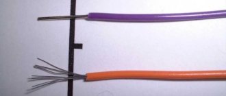
Testing a cable with colored wires, schematic connection of probes to single-color wires at different ends of the cable. A – cable insulation. B – Individual cable cores with colored insulation.
- With single-color wires or a laid out cable, where the distance does not allow the tester to work with different ends at the same time, all wires at one end are shorted together.
- On the other side of the cable, connect the probe to one wire and call all the other wires through it, in turn 1,2,3....
Testing a cable with wires of the same color
The disadvantage of this method is that it is not possible to isolate each core individually and label it. This must be done when the cable is rolled up in one place or using a transformer.
Independent dialing
It is best to ring the telephone cable using the handset of the device. This method is characterized by simplicity and mobility.
- An assistant is invited.
- The common core is determined. She can be anyone. Others are called in relation to the selected core. The selected one must be ringing initially.
- The first clamp of the main tube is connected to the main core. The second - to the other.
- The first clamp of the auxiliary tube is connected to the main core on the opposite side of the cable.
- The second switches alternately over the others. You need to find the one to which the assistant connected.
- When connected to the desired core, a crackling sound will be heard, indicating the occurrence of a closed circuit.
- A method for marking the detected core is discussed with an assistant. Pre-prepared tags are placed on the ringed type of core on both sides.
- The process is repeated for each subsequent wire.
- If there is no break, the conductors are inserted into the terminal block.
You can also ring your phone
Testing wires with a multimeter
GE 2524 multimeter in the continuity position
The probe with the black wire is inserted into the connector with the ground symbol (housing), red above, into the connector for measuring resistance with the Ohm symbol “ Ω”. The disadvantage of many digital multimeters in dial mode is the delay in the sound indicator signal when touching the contacts. It is necessary to fix the probes on the wire for 2-3 seconds to make sure there is contact. This inertia in operation creates some difficulties in checking the integrity of the wire.
Multimeters of the UNI-T type have good performance in dialing mode; the sound indicator operates almost instantly when the contacts are closed.
Comparison table of characteristics of Fluke-179 and UNI-T UN61 multimeters
Please note that for all instruments it is advisable to use probes with gold-plated rods. Unlike steel ones, they are not subject to oxidation and provide reliable electrical contact.
Continuity using a transformer
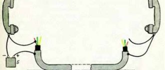
This method is effective for testing unrolled laid cables with wires of the same color. In this case, step-down transformers are used with different voltages at the taps of the secondary winding.
- The primary winding of the transformer is connected to a 220V AC source;
- The beginning of the secondary winding to the ground loop, to which the cable shield is closed;
- The remaining secondary winding taps with different voltages to the ends of the wires;
- On the other side of the cable, a multimeter is used to measure the corresponding voltage between the ground loop and the cable wires. Thus, the integrity of the core is checked and marked.
Diagram for connecting the cable to the transformer for dialing.
The multimeter is set to AC voltage measurement mode. It is recommended to use devices from Western manufacturers, since in this case the measurement mode is used, not the indication mode. Chinese S-99 type multimeters are very poorly calibrated; inaccurate voltage measurements can lead to errors when marking the cable. Therefore, for tapping a cable using a transformer, where voltage measurements are made, it is better to use a pointer device of the Ts-4342-M1 type.
Characteristics of the combined device Ts 4342 M1:
| Accuracy class | 2,5/4,0 |
| measurement ranges | |
| DC current in mA | 0,05 — 2500 |
| AC current in mA | 0,25 — 2500 |
| Voltage, DC | 0,1 — 1000 |
| Variable voltage in volts | 1,0 — 1000 |
| DC resistance in kOhm | 0,3 — 10000 |
| signal level when measuring voltage in dB(-) | -10 to+15 |
| frequency range in Hz | 45 — 2000 |
| Power supply | autonomous |
| Dimensions in mm | 215*115*90 |
| Weight in kg | 0,9 |
| operating temperature | from -10 to +40°С |
In most cases, all multimeters have a classic layout of controls with minor differences.
When taking measurements, you need to carefully look at the inscriptions with symbols. Summary table of main parameters for different models of multimeters:
| Model | LCD screen | U— | V~ | I— | I~ | R | The dial is connected. | Diode testing | Transistor testing |
| M830B | 7 segments 3.5 digits | 0.1mV - 1000V | 0.1V - 700V | 0.1mA- 10A | — | 0.1W-2mW | — | * | * |
| M830 | 7 segments 3.5 digits | 0.1mV - 1000V | 0.1V - 700V | 0.1mA- 10A | — | 0.1mW - 2mW | * | * | * |
| M832 | 7 segments 3.5 digits | 0.1mV - 1000V | 0.1V - 700V | 1mA- 10A | — | 0.1W-2mW | * | * | * |
| M838 | 7 segments 3.5 digits | 0.1mV - 1000V | 0.1V - 700V | 1mA- 10A | — | 0.1W-2mW | * | * | * |
To set the multimeter to the AC voltage measurement mode, you need to set the batch switch for changing modes in the sector with the “ V ~” icon to the maximum value within which measurements are taken. In our case, this will be any measurement limit greater than 20V; the wires from the probes are installed in the same connectors as when measuring resistance.
Making calls using handsets
The advantage of this method is that it is convenient to ring unrolled cables with wires of the same color. At the same time, electricians can communicate with each other. The disadvantage is that one person cannot do the work this way.
You will need two handsets and one battery, 4.5 volts is enough.
- Connect a 4.5 V battery into the microphone wire coming out of the handset. (Polarity does not matter). The main thing is that the current is constant and stable, without ripples, if not a battery is used, but a rectifier from an industrial network.
Connecting the power source to the handset, please note that polarity does not matter, the main thing is that the battery is connected to the circuit in front of the microphone.
- Connect the end of the wire connected to the capsule to the shielding sheath of the cable, the second to one of the cores;
- On the other side of the cable, the second tube is connected with one wire to the shielding sheath. The second wire is connected to different wires in turn until the installer at the other end of the cable responds.
Connecting tubes to a cable for wire testing; the positive wire can be connected to the shielding sheath on the cable or to the metal pipe in which it is laid. But it must be taken into account that the pipe must be solid or have electrical contact with a common ground loop for both sides of the cable.
Tip #1. To make the design easier, use a microphone headset from cell phones; in some cases this is very convenient.
Diagram for connecting micro headphones to a handset instead of a telephone capsule.
Testing the cable with an indicator device with a light bulb
To do this you will need any power supply, a 1.5 battery; 4.5 or 9 Volts, wires with alligator clips and a lamp for the appropriate voltage.
Assembly of the circuit and procedure for use:
- Wires are soldered to the battery terminals;
- In the break of one of the wires, the polarity does not matter, connect an LED or a lamp;
- The dialing process is carried out using the same method as with a tester or multimeter. In this case, if the conductor is intact, instead of the arrow deflecting or the reading on the liquid crystal display, the light will light.
Such an indicator device allows you to test cables over distances of several hundred meters, depending on the state of charge of the battery.
Connection diagram for an indicator device with a light bulb for cable testing.
Tip No. 2 During installation work, when the lamps are constantly moving, it is recommended to use an LED. It is less susceptible to mechanical stress than a conventional incandescent lamp with a spiral and a glass bulb.
Homemade sound probe for continuity testing
Home» Measurements» Probe circuits for testing installations, probes with sound may be of interest to radio amateurs.
There are several ways to ring wires at home:
You can learn how to ring the wires of a light bulb and a battery from this video lesson:
Using a multimeter . This device measures various parameters of the electrical network (for example, voltage, current, resistance). In the house, such a device will be indispensable if you need to check an outlet or switch, check for a break, or find out where the wire goes.
The most common mistakes made when testing cables
- Incorrect setting of measurement modes or connection of probes to the sockets of the multimeter or tester. On old pointer testers, the operating mode switch is set to the 1 kOhm position, on modern devices in the dialing mode, with a diode or buzzer sign;
- When testing wires using a step-down transformer, use a pointer tester to check the power source. The voltage should be from 3.5 to 4.5 volts, otherwise the voltage will be measured with a large error;
- Before testing, thoroughly clean the contacts on the cable wires and test leads. Gold-plated contacts do not need to be cleaned; you can wipe them with cotton wool and industrial alcohol.
- When using pointer instruments, do not confuse the scale when measuring; it should be for alternating voltage with the sign “V~”.
- When testing wires in the distribution cabinet harnesses, the contacts on both sides must be disconnected from all elements of the equipment.
- Technical characteristics of PRKA wire
General purpose test kits with low pass filter
Functionally, these sets are practically no different from those described earlier. However, the inductive probes included in these kits have one additional operating mode:
- broadband (as in the previously described sets);
- — using a 50 Hz filter.
In the 50 Hz filter mode, interference from the power supply is filtered out. This reduces the level of extraneous noise when working in rooms with a large concentration of active equipment (server rooms, data centers, telephone exchanges, etc.)
| Fluke Networks PRO3000F50-KIT | Greenlee 801K | |
| Identification of cores in a multi-pair cable | • | • |
| Determining the polarity of a telephone line | • | • |
| Wiring Continuity Testing | • | • |
| Supply of conversational voltage to organize a communication channel over a disconnected line | • | |
| AC noise filter, 50 Hz | • | • |
| Generator output power | +8 dBm | +10 dBm |
| Headset jack | • | |
| Needle-plated crocodiles | • | • |