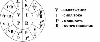
What is reactive power?
First, let's look at the concept of electrical power. In the broadest sense of the word, this term means work performed per unit of time. In relation to electrical energy, we will slightly correct the concept of power: by electrical power we will understand a physical quantity that actually characterizes the rate of current generation or the amount of transmitted or consumed electricity per unit of time.
It is clear that the work of electricity per unit time is determined by electrical power, measured in watts. The instantaneous power in a section of the circuit is found by the formula: P = U×I, where U and I are the instantaneous values of the voltage and current parameters in this section.
Strictly speaking, the above formula is valid only for direct current. However, in sinusoidal current circuits, the formula only works when the consumer load is purely active. With a resistive load, all electrical energy is spent doing useful work. Examples of resistive loads are resistive devices such as a boiler or an incandescent lamp.
If there are capacitive or inductive loads in the electrical circuit, parasitic currents appear that are not involved in performing useful work. The power of these currents is called reactive.
With inductive and capacitive loads, some of the electricity is dissipated as heat, and some prevents useful work from being done.
Where does it come from?
The formation of the name “reactive power” refers to the need to release the energy that is consumed by the load to form electromagnetic fields.
This component is used for inductive type. For example, when connecting electric motors. All household appliances, as well as some industrial and agricultural facilities, use this type of load.
Three main types using the example of a generator
In electrical circuits, when the work is active, the current inside does not lag behind the voltage readings. If the energy is of an inductive type, then the current will lag, unlike the voltage. With capacitive, the current will flow faster than the voltage. Below, three types of work are discussed in detail, as well as their scope of application.
Physics of the process
When we are dealing with DC circuits, there is no need to talk about reactive power. In such circuits, the values of instantaneous and total power are the same. The exception is the moments of switching on and off capacitive and inductive loads.
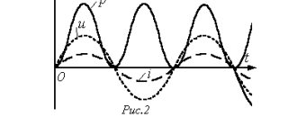
A similar situation occurs in the presence of purely active resistances in sinusoidal circuits. However, if devices with inductive or capacitive reactances are included in such an electrical circuit, a phase shift occurs in current and voltage (see Fig. 1).
In this case, a phase lag of the current is observed on inductances, and on capacitive elements the phase of the current shifts so that the current leads the voltage. Due to the violation of the current harmonics, the total power is decomposed into two components. Capacitive and inductive components are called reactive and useless. The second component consists of active capacities.
Rice. 1. Phase shift by inductive load
The phase shift angle is used when calculating the values of active and reactive capacitive or inductive powers. If the angle φ = 0, which occurs with resistive loads, then there is no reactive component.
Important to remember:
- the resistor consumes exclusively active power, which is released in the form of heat and light;
- inductors provoke the formation of a reactive component and return it in the form of magnetic fields;
- Capacitive elements (capacitors) cause the appearance of reactance.
Coil equivalent circuit with series connection of elements
In a circuit with a series connection of elements, a real coil is characterized by active resistance R and inductance L.
Active resistance is determined by the amount of power loss
R = P/I2
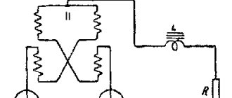
and inductance is determined by the design of the coil. Let us assume that the current in the coil (Fig. 13.9, a) is expressed by the equation i = Imsinωt . It is necessary to determine the voltage in the circuit and power. With alternating current, an e occurs in the coil. d.s. self-induction eL therefore the current depends on the action of the applied voltage and emf eL. The equation of electrical equilibrium of the circuit, compiled according to Kirchhoff’s second law, has the form:
The voltage applied to the coil consists of two terms, one of which uR is equal to the voltage drop in the active resistance, and the other uL balances the self-induction emf.
In accordance with this, the coil in the equivalent circuit can be represented by active and inductive resistances connected in series (Fig. 13.9, b). Additionally, note that both terms on the right side of equality (13.12) are sinusoidal functions of time. According to the conclusions obtained in these previous two (first, second) articles, we get that uR is in phase with the current, UL is ahead of the current by 90°.
That's why:
u = R* Imsinωt + ωL Im sin(ωt+ π/2).
Reactive energy source
To understand the nature of the appearance of this energy and how to find reactive power, it is necessary to clarify that any electromagnetic or induction machine that operates on alternating current converts electricity into heat. For this transformation to occur, a magnetic field is needed. It, accordingly, is formed by watt-free energy. The reason is the absorption of energy from the induction circuit and its release back when the magnetic field decreases twice per power frequency cycle.
Nature of the phenomenon
Starting current
When calculating, it is necessary to take into account the starting currents of the device. For example, the resistance of the filament in a light bulb at the moment of switching on is 10 times less than in operating mode. Therefore, the starting current of this light bulb is 10 times greater. After some time, it will begin to consume the power that is recorded in the data of this light bulb. Therefore, when turned on, it burns out due to high inrush currents.
In electronic equipment, until the capacitor in the power supply is charged, an inrush current is also generated.
In electric motors, a starting current is also generated until the engine reaches rated speed.
In heating devices, a starting current is generated until the coil heats up to the standby temperature.
Why is it needed?
Electricity transfers energy to a conductor to carry out a technical process. For the process to occur, the transferred force must be converted into heat and voltage. In this case, electricity must be supplied constantly, which is ensured by both types of power characteristics. The active one provides useful force, and the reactive one supports it in electric motor, transformer, furnace, welding, throttle and lighting installations.
Power in an alternating current circuit
Electrical appliances connected to the electrical network operate in an alternating current circuit, so we will consider power under these conditions. However, first, let's give a general definition of the concept.
Power is a physical quantity that reflects the rate of conversion or transmission of electrical energy.
In a narrower sense, they say that electrical power is the ratio of the work performed over a certain period of time to this period of time.
If we rephrase this definition less scientifically, it turns out that power is a certain amount of energy that is consumed by the consumer over a certain period of time. The simplest example is an ordinary incandescent lamp. The rate at which a light bulb converts the electricity it consumes into heat and light is its power. Accordingly, the higher this indicator is initially for a light bulb, the more energy it will consume and the more light it will give off.
Since in this case there is not only a process of converting electricity into some other (light, heat, etc.), but also a process of oscillation of the electric and magnetic field, a phase shift appears between the current and voltage, and this should be taken into account in further calculations.
It will be interesting➡ Comparator operating principle. Features of a voltage comparator
When calculating power in an alternating current circuit, it is customary to distinguish active, reactive and apparent components.
Concept of active power
Active “useful” power is that part of the power that directly characterizes the process of converting electrical energy into some other energy. It is designated by the Latin letter P and measured in watts (W).
Calculated using the formula: P = U⋅I⋅cosφ,
where U and I are the root mean square value of the voltage and current of the circuit, respectively, cos φ is the cosine of the phase shift angle between voltage and current.
IMPORTANT! The formula described earlier is suitable for calculating circuits with a voltage of 220V, however, powerful units usually use a network with a voltage of 380V. In this case, the expression should be multiplied by the root of three or 1.73
Reactive power concept
Reactive “harmful” power is the power that is generated during the operation of electrical appliances with an inductive or capacitive load, and reflects the occurring electromagnetic oscillations. Simply put, this is energy that moves from the power source to the consumer, and then returns back to the network.
Naturally, this component cannot be used in business; moreover, it greatly harms the power supply network, which is why they usually try to compensate for it.
This value is denoted by the Latin letter Q.
REMEMBER! Reactive power is measured not in the usual watts (W), but in reactive volt-amperes (Var).
Calculated using the formula:
Q = U⋅I⋅sinφ,
where U and I are the rms value of the voltage and current of the circuit, respectively, sinφ is the sine of the phase shift angle between voltage and current.
IMPORTANT! When calculating, this value can be either positive or negative, depending on the phase movement.
The main difference between a reactive (capacitive and inductive) load is the presence, in fact, of capacitance and inductance, which tend to store energy and later release it into the network.
Power factor cosφ (read cosine phi) is a scalar physical quantity that reflects the efficiency of electrical energy consumption. Simply put, the cosφ coefficient shows the presence of a reactive part and the magnitude of the resulting active part relative to the total power.
The cosφ coefficient is found through the ratio of active electrical power to total electrical power.
NOTE! For a more accurate calculation, nonlinear distortions of the sinusoid should be taken into account, however, in conventional calculations they are neglected.
The value of this coefficient can vary from 0 to 1 (if the calculation is carried out as a percentage, then from 0% to 100%). From the calculation formula it is not difficult to understand that the greater its value, the greater the active component, which means the better the performance of the device.
An inductive load converts the energy of an electric current first into a magnetic field (during half a half cycle), and then converts the energy of the magnetic field into an electric current and transmits it to the network. Examples include asynchronous motors, rectifiers, transformers, and electromagnets.
IMPORTANT! When operating an inductive load, the current curve always lags the voltage curve by half a half cycle.
A capacitive load converts the energy of an electric current into an electric field, and then converts the energy of the resulting field back into an electric current. Both processes again occur for half a half cycle each. Examples are capacitors, batteries, synchronous motors.
IMPORTANT! During operation of a capacitive load, the current curve leads the voltage curve by half a half cycle.
Concept of total power. Capacity Triangle
Apparent power is a geometrically calculated value equal to the root of the sum of the squares of active and reactive powers, respectively. Denoted by the Latin letter S.
You can also calculate the total power by multiplying the voltage and current respectively.
S = U⋅I
IMPORTANT! Apparent power is measured in volt-amperes (VA).
The power triangle is a convenient representation of all the previously described calculations and relationships between active, reactive and apparent power.
The legs reflect the reactive and active components, the hypotenuse – the full power. According to the laws of geometry, the cosine of the angle φ is equal to the ratio of the active and total components, that is, it is the power factor.
Calculations
To calculate the total power, use the formula in complex form. For example, for a generator the calculation looks like:
And for the consumer:
But let’s put this knowledge into practice and figure out how to calculate power consumption. As you know, we, ordinary consumers, pay only for the consumption of the active component of electricity:
P=S*cosФ
Here we see a new value of cosФ. This is the power factor, where Ф is the angle between the active and full components of the triangle. Then:
cosФ=P/S
In turn, reactive power is calculated using the formula:
Q = U*I*sinФ
To reinforce the information, watch the video lecture:
All of the above is also true for a three-phase circuit; only the formulas will differ.
Engine reactive power accounting
Now let's see how the active energy is calculated for the same electric motors, on which the performance of a modern enterprise depends 70-80% - they turn pumps, machines, fans, conveyors, etc. and so on. If this is the case, then someone must constantly ensure that power consumption does not suddenly become unreasonably high. Of course, such control will most likely be carried out by a computer, but not without the participation of a person (engineer).
Most of all, the reactive energy of power is wasted in cases where the engine is idling, and if for pumps or conveyors this is an insignificant part, then for machine tools it is a very noticeable waste of the reactant. But, the threshold for the most efficient operation of electric motors is in the range of 60-100%, and at lower rates the useless energy consumption is increasingly approaching the idle value. What does this mean? The fact that when designing a workshop one should not overestimate its capacity - in practice this will only harm production.
Note: world practice shows that recently process engineers at leading enterprises are abandoning wound rotors and giving preference to asynchronous motors with a squirrel-cage rotor.
Occurrence of reactive power
Let's say the circuit contains a DC power supply and an ideal inductance. Turning on the circuit generates a transient process. The voltage tends to reach the nominal value; the growth is actively hampered by the inductance’s own flux linkage. Each turn of the wire is bent in a circular path. The resulting magnetic field will cross the adjacent segment. If the turns are located one after the other, the nature of the interaction will increase. This is called intrinsic flux linkage.
It will be interesting➡ Making conductive glue from scrap materials
The nature of the process is as follows: the induced EMF prevents changes in the field. The current tries to grow rapidly, the flux linkage pulls back. Instead of a step we see a smoothed protrusion. The energy of the magnetic field is spent to interfere with the process that created it. The case of reactive power occurrence. The phase differs from the beneficial one and is harmful. Ideal: the direction of the vector is perpendicular to the active component. It is assumed that the wire resistance is zero (a fantastic scenario).
When the circuit is turned off, the process will be repeated in reverse order. The current tends to instantly drop to zero; energy is stored in the magnetic field. If the inductance disappears, the transition will take place suddenly, flux linkage gives the process a different coloring:
- A decrease in current causes a decrease in the magnetic field strength.
- The effect produced induces the back-EMF of the turns.
- As a result, after the power source is turned off, the current continues to exist, gradually attenuating.
Graphs of voltage, current, power
Reactive power is a certain link of inertia, constantly lagging and interfering. The first question is: why then are inductors needed? Oh, they have plenty of useful qualities. Benefit makes you put up with reactive power. A common positive effect is the operation of electric motors. Energy transfer occurs through magnetic flux. Between the turns of one coil, as shown above. A permanent magnet, a choke, and everything capable of being captured by an induction vector are subject to interaction.
The cases cannot be called comprehensive in a descriptive sense. Sometimes clutch flow is used in the form shown as an example. The principle is used by ballasts of gas-discharge lamps. The inductor is equipped with a myriad of turns: turning off the voltage does not cause a smooth decrease in current, but a surge of large amplitude of the opposite polarity. The inductance is great: the response is truly amazing. Exceeds the original 230 volts by an order of magnitude. It is enough for a spark to appear and the light bulb to light up.
Reactive power and capacitors
Reactive power is stored by magnetic field energy by inductances. What about the capacitor? Acts as a source of the reactive component. Let us supplement the review with the theory of vector addition. The average reader will understand. Oscillatory processes are often used in the physics of electrical networks. The well-known 220 volts (now accepted 230) in a 50 Hz outlet. A sine wave whose amplitude is 315 volts. When analyzing circuits, it is convenient to represent them as a clockwise rotating vector.
Graphical circuit analysis
The calculation is simplified and the engineering representation of reactive power can be clarified. The current phase angle is considered equal to zero and is plotted to the right along the abscissa axis (see figure). The reactive energy of the inductance is in phase with the UL voltage and is 90 degrees ahead of the current. Ideal case. Practitioners have to take into account the winding resistance. Part of the power will be reactive in inductance (see figure). The angle between projections is important. The value is called power factor. What does this mean in practice? Before answering the question, let's consider the concept of a resistance triangle.
Practical interpretation of power factor
Many people notice a discrepancy in the case of practical consideration of reactive power. To reduce the coefficient, it is recommended to include large capacitors in parallel with the motor windings. The inductive reactance balances the capacitive reactance, the current is again in phase with the voltage. It's difficult to understand for this reason:
- Let's say the primary winding of a transformer is connected to an alternating voltage source.
- Ideally, active resistance is zero. Power must be reactive. But this is bad: they tend to make the angle between voltage and current zero!
Power factor
The amount of energy stored by the field is determined by the size of the inductance or capacitance. You can read it in any physics textbook for universities (Physics Course by Zhdanov and Maranjyan, vol. 2, p. 234), more precisely, it is proportional to the square of the quantity. The theory of reactive power assumes: a certain energy is stored each period by parasitic inductance, capacitance, and then goes into the external circuit. This results in a kind of circulation inside the oscillatory circuit. The connecting wires become very hot if the inductance is too far from the capacitance.
But! The oscillatory process is indifferent to the operation of motors and transformers. The theory of reactive power assumes that all energy oscillates. To the last drop. In a transformer or motor, an active “leakage” of energy occurs from the field to perform work and induce current in the secondary winding. Energy cannot circulate between source and consumer.
In a real chain, the process of coordinating individual sections makes it difficult. To be on the safe side, suppliers require that capacitors be installed in parallel with the motor winding so that the energy circulates in the local segment and does not escape outside, heating the connecting wires. It is important to avoid overcompensation. If the capacitors are too large, the battery will cause the power factor to increase.
As for the phase shift, it occurs on the secondary winding of the substation transformer. That's not the role. The engine is running, some of the energy is not converted into useful work and is reflected back. The result is a power factor. The participating component of inductance is a technological, structural defect. The part that is not useful. We will compensate by adding capacitor blocks.
The correct matching is checked based on the fact that there is no phase shift between the voltage and current of a running electric motor. Excess energy circulates between the excess inductance of the windings and the installed capacitor unit. The goal of the event was achieved - to avoid heating the conductors of the network supplying the device.
It will be interesting➡ Inductive reactance
Reactive electricity concept
This type of electricity is inherent in circuits that contain reactive elements. Reactive electricity is the portion of the total incoming power that is not spent on useful work.
In DC circuits there is no concept of reactive power. In AC circuits, a reactive component occurs only when an inductive or capacitive load is present. In this case, there is a mismatch between the phase of the current and the phase of the voltage. This phase shift between voltage and current is indicated by the symbol “φ”.
With an inductive load in the circuit, a phase lag is observed, and with a capacitive load, it is advanced. Therefore, only part of the total power reaches the consumer, and the main losses occur due to useless heating of devices and instruments during operation.
Power losses occur due to the presence of inductive coils and capacitors in electrical devices. Because of them, electricity accumulates in the circuit for some time. After this, the stored energy is fed back into the circuit. Devices whose power consumption includes a reactive component of electricity include portable power tools, electric motors and various household appliances. This value is calculated taking into account a special power factor, which is designated as cos φ.
Vector diagram of a real coil and its total resistance
The phase mismatch of the terms in expression (13.12) makes it difficult to determine the amplitude and effective value of the voltage U applied to the circuit. Therefore, we will use the vector method of adding sinusoidal quantities. Amplitudes of the total voltage components
UmR = RIm; UmL = ωLIm,
and the effective quantities
UR = RI; UL = XLI.
Total voltage vector
U = UR + UL
In order to find the magnitude of the vector U , let's construct a vector diagram (Fig. 13.10, a), having previously selected the scales of the current Mi and voltage Mu.
the current vector I as the initial vector of the diagram . The direction of this vector coincides with the positive direction of the axis from which the phase angles are measured (initial phase of the given current Ψi =0). As before, it is convenient (but not necessary) to direct this axis horizontally.
Vector UR coincides in direction with current vector I , and vector UL is directed perpendicular to vector I with a positive angle.
The diagram shows that the current vector I of the total voltage U reflects the current vector I at an angle φ >0, but φ <90°, and is equal in magnitude to the hypotenuse of a right triangle, the legs of which are the vectors of voltage drops in the active and inductive resistances UR and UL :
UR = Ucosφ
The projection of the voltage vector U onto the direction of the current vector is called the active component of the voltage vector and is designated Ua. For a coil according to the diagram in Fig. 13.9 at Ua = UR
U = Usinφ (13.14)
The projection of the voltage vector U onto the direction perpendicular to the current vector is called the reactive component of the voltage vector and is denoted Up . For coil Up = UL
At current i = Imsinωt the voltage equation can be written based on the vector diagram in the form
U = Umsin(ωt+φ)
of the voltage triangle, expressed in units of voltage, by the current I. We obtain a similar triangle of resistance (Fig. 13.10, b), the legs of which are active R = UR/I and inductive XL = UL/I , resistance, and the hypotenuse is the value Z = U/I .
The ratio of the effective voltage to the effective current of a given circuit is called the total resistance of the circuit. The sides of the resistance triangle cannot be considered vectors, since resistances are not functions of time. From the triangle of resistance it follows
The concept of circuit impedance Z allows us to express the relationship between the effective values of voltage and current with a formula similar to Ohm’s formula:
From the triangles of resistance and voltage are determined
cosφ = UR/U = R/Z; sinφ = UL/U = XL/Z; tgφ = UL/UR = XL/R. (13.18)
Reactive power calculation
The power factor ranges from 0.5 to 0.9; The exact value of this parameter can be found in the electrical device data sheet. The apparent power must be determined as the active power divided by the factor.
For example, if the passport of an electric drill indicates a power of 600 W and a value of 0.6, then the total power consumed by the device will be equal to 600/06, that is, 1000 VA. In the absence of passports for calculating the total power of the device, the coefficient can be taken equal to 0.7.
Since one of the main tasks of existing power supply systems is to deliver useful power to the end user, reactive power losses are considered a negative factor, and an increase in this indicator calls into question the efficiency of the electrical circuit as a whole. The balance of active and reactive power in a circuit can be visualized in the form of this funny picture:
Power triangle and cosine Phi
If you take the entire circuit, analyze its composition, phases of currents and voltages, then construct a vector diagram. After this, draw the active one along the horizontal axis, and the reactive one along the vertical axis and connect the ends of these vectors with the resulting vector - you get a triangle of powers.
It expresses the ratio of active and reactive power, and the vector connecting the ends of the two previous vectors will express the total power. This all sounds too dry and confusing, so look at the picture below:
The letter P denotes active power, Q – reactive power, S – apparent power.
The total power formula is:
The most attentive readers probably noticed the similarity of the formula to the Pythagorean theorem.
Units:
- P – W, kW (Watts);
- Q – VAR, kVAr (reactive volt-amperes);
- S – VA (Volt-Amps);
Differences
The difference between the values is that the active power characteristic shows the efficiency of the devices, and the reactive one is the transfer of this efficiency. The difference is also observed in definition, symbol, formula and significance.
You might be interested in Features of kW and kVA units of measurement
Note! As for the meaning, the second is needed only to control the voltage created from the first value and overcome power fluctuations.
The meaning of reactive load
Any reactive load creates a time shift between the phases of current and voltage. This value is measured in degrees. The most visual is the vector representation of electrical parameters. If you connect an inductance, the voltage will lead the current. The angle between them is denoted in formulas by the letter “ϕ” (“Phi” in Greek).
Time and vector diagrams show how the main parameters change when connecting inductive (capacitive) elements
The picture shows that when a capacitive load is connected, the vectors “swap” places. Under ideal conditions, the shift between vectors is 90°. In reality, one should take into account the influence of electrical resistance of the circuit and imperfect designs. Taking into account the characteristics of the elements, it should be recalled that in the inductance (capacitance), while maintaining the parameters of the power source, the current (voltage) changes smoothly, respectively.
Why is the voltage in the network variable?
To explain the present situation, we need to make a brief excursion into history. Electricity has been known to man for hundreds (according to some sources, thousands of years). However, the truly massive use of this energy began relatively recently - at the end of the 19th century. It was then (1879) that Edison patented the first functional device that helped solve lighting problems. To power light bulbs, he began installing DC networks.
Ten years later, Tesla created alternating current generators. After fierce competition, it was his method of transmitting energy over distances that won. This result was achieved more by market methods than by careful comparison of consumer characteristics.