Electrical appliances can be turned on and off according to a planned schedule automatically without user intervention; for this, there are special devices that close contacts at the desired moment, determined by the setting. Some products are initially supplied by manufacturers with a programmable circuit breaker. For devices without it, they purchase such a device, but they also design a time relay with their own hands. Let's analyze several proven methods for assembling an on/off timer.
Control devices and time relays
The equipment we offer is designed to work as part of a variety of monitoring and dispatching systems. Control devices carry out the process of working with m2m systems: they control microclimate systems, implement cyclic switching of electrical networks at unattended facilities.
- time delay relay;
- data collection devices;
- controllers BRKV (rotation unit for air conditioning and ventilation);
- sensors;
- and other auxiliary elements.
In addition to the indicated control and automation devices, auxiliary elements for them are available. For example, a bracket for a transmitter. All control devices and time relays are made of high-strength materials that are not subject to fire and corrosive influences.
RVs are used where there is a need:
- execute commands with a certain selectivity, i.e. selectivity;
- turn on and off the load at a certain time, i.e. use RV as a timer;
- perform a series of sequential (programmed) actions or commands spaced over time;
- execute a command for a specified period of time.
Thus, the functions of the time relay are extremely diverse, and the time delays that can be used range from tenths of a second to tens of hours or days. The upper limit of shutter speed is limited only by the imagination of the author of the device.
Selectivity is used most often in relay protection devices. For example, there is a power line fed by a switch at the head and sectioned by a switch in the middle. The protection is mounted on the head switch. A short circuit (short circuit) occurs on it. How does line protection behave? Since the protection itself cannot determine the location of the short circuit, it is made selective using a time relay. With the first time delay, say 0.5 seconds, the sectional switch is turned off. If the short circuit is not eliminated, then it is closer to the power switch, then with a second delay, say, 1.0 second, the main circuit breaker is turned off. KZ has been eliminated.
The load switch function is widely used to control, say, object lighting. They turn on and off at a certain time. The program action function is widely used in industry when it is necessary to perform a series of actions, for example:
- turn on the boiler furnace ventilation at time X for Y minutes;
- allow fuel supply to the burners during X + Y.
This is already program work of the radio and work for a given period of time.
Self-production
If you wish, you can make a timer for turning on and off electrical appliances with your own hands. Before you begin, you need to decide on the tasks, find the device diagram and the required radio components. Schemes exist of varying degrees of complexity.
Transistor relay circuit
A simple 12 V turn-off delay relay circuit is assembled on a single transistor and does not contain scarce parts. This is a very easy to follow pattern. After assembly, no configuration is required. Such a device will work no worse than one purchased in a store.
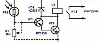
Any npn conductivity transistor is used as VT1. When power is applied, the capacitor is charged. When the voltage threshold is reached, the transistor opens and relay K1 is activated. By changing the value of C1 and R2, the on time is adjusted. The switch-on delay in this design reaches 10 seconds. In order for the relay to remain closed for some time when the power is removed, a large capacitor is installed in parallel with the power supply to the circuit.
On-chip delay control
A simple circuit for controlling a light, fan, or other load can be assembled on the NE555. The NE555 specialized chip is nothing more than a timer. The output current of the device is 200 mA, the current consumption is 203 mA. The timer error does not exceed one percent and does not depend on changes in the signal in the 220 volt network.
The circuit operates from a constant voltage source. The circuit power signal level is selectable in the range from 9 to 14 Volts. A chain consisting of resistors R2, R4 and capacitor C1 sets the delay time. You can calculate this time using the formula t = 1.1*R2*R4*C1. After pressing the SB1 button, contacts K1.1 are closed. After time t they will open. In order for the timer to start counting time not from the moment the button is pressed, but at the moment it is released, you will need to use a button with normally closed contacts.
The adjustment time can be easily adjusted using variable resistor R2. It is convenient to assemble such a circuit on a board made of PCB or getinax. After correct assembly and with working radio components, the circuit works immediately.
To ensure precise intervals of time when performing various actions using electrical equipment, time relays are used.
They are used everywhere in everyday life: electronic alarm clock, changing operating modes of a washing machine, microwave oven, exhaust fans in the toilet and bathroom, automatic watering of plants, etc.
Room thermostat and energy saving
To get a more functional option, let’s add here a device for monitoring the air temperature in the room - a room thermostat.
It doesn’t matter to him what the temperature of the boiler water will be; he reacts precisely to the comfortable air temperature in your home. By analogy with the previous elements, mount it in the gap, in front of the working thermostat. The second simplest scheme is ready
The second simplest scheme is ready
By analogy with the previous elements, mount it in the gap, in front of the working thermostat. The second simplest scheme is ready.
But people always strive for more, and in addition to the comfort of electric heating, they always want to save money. Still, with rare exceptions, electric heating is not exactly a cheap thing in our realities.
How to do this by improving the above connection diagram? There is a night rate for this business.
To take full advantage of it, we need a time relay.
It will start electric heating only during a specified period of the day. Place it in the circuit in front of the room thermostat.
However, pay attention to one nuance. If there is such a device in the circuit, a minimum air temperature thermostat must be mounted parallel to it. During the day, in your absence, the temperature outside may drop sharply
We left at -5C, arrived in the evening - minus 25C outside. Accordingly, your home will become significantly colder
During the day, in your absence, the temperature outside can drop sharply. We left at -5C, arrived in the evening - minus 25C outside. Accordingly, your home will become significantly colder.
It will start heating as soon as the temperature in the house drops below the minimum threshold. As a result, it will prevent the house from cooling down and the system from defrosting.
To visually observe whether the sensors are turned on or off at the moment, you can connect a signal light to a common point in front of the microswitches and display it in a visible place.
This is especially useful when the control panel and the boiler itself are located in the basement of the house or in a neighboring outbuilding.
Most factory electric heating boilers are built precisely on such basic control schemes. There is one supply line (phase) that supplies a signal to the coil of the device with power elements, and all additional equipment, sensors and switches are “hung” on this very line, performing protective and monitoring functions.
As you can see, there is nothing complicated or intricate here.
https://youtube.com/watch?v=fw9BUOGXT4Y%3F
Magnetic starter connection diagrams.
The first, classic scheme, is intended for the usual start of an electric motor: the “Start” button is pressed - the engine turns on, the “Stop” button is pressed - the engine turns off. Moreover, instead of a motor, you can connect any load, for example, a powerful heating element.
For ease of understanding, the circuit is divided into two parts: power part
and
control circuits
.
Power section
powered by three-phase alternating voltage 380V with phases “A” “B” “C”.
The power part includes: three-pole circuit breaker QF1
, three pairs of power contacts of the magnetic starter
1L1-2T1
,
3L2-4T2
,
5L3-6T3
and a three-phase asynchronous electric.
engine M.
_
Control circuit
receives power from phase “A”.
The control circuit diagram includes the SB1
“Stop” button, the
SB2
“Start” button, the magnetic starter coil
KM1
and its auxiliary contact
13NO-14NO
, connected
in parallel with
the “Start” button.
When turning on the QF1
phases “A”, “B”, “C” arrive at the upper contacts of the magnetic starter
1L1
,
3L2
,
5L3
and are on duty there.
Phase “A”, which supplies the control circuits, comes through the “Stop” button to contact No. 3
of the “Start” button, the auxiliary contact of the starter
13NO
and also remains on duty at these two contacts. The circuit is ready for use.
When you press the “Start” button, phase “A” hits the coil of the KM1
, the starter is triggered and all its contacts are closed.
Voltage appears at the lower power contacts 2T1
,
4T2
,
6T3
and from them is supplied to the electrical circuit. engine. The engine starts to rotate.
You can release the "Start" button and the engine will not turn off, since using the auxiliary contact of the starter 13NO-14NO
, connected
in parallel to
the “Start” button,
self-recovery
.
It turns out that after releasing the “Start” button, the phase continues to flow to the coil of the magnetic starter, but through its 13NO-14NO
. In the lower figure, the arrow shows the movement of phase “A”.
And if there is no self-recovery, you will have to keep pressing the “Start” button all the time while the electric power is working. motor or any other load powered by a magnetic starter.
To turn off email. engine, just press the “Stop” button: the circuit will break, the control voltage will stop flowing to the starter coil, the return spring will return the core with the power contacts to its original position, the power contacts will open and disconnect the engine from the three-phase supply voltage.
Now let's look at the editing room
starter control circuit diagram. Here everything is almost the same as in the circuit diagram, with the slight exception of the implementation of self-retaining.
In order not to pull an extra wire to the “Start” button, a jumper is placed between the coil output and one of the nearby auxiliary contacts: in this case it is “ A2
" and "
14NO
".
And from the opposite auxiliary contact the wire runs directly to contact No. 3
of the “Start” button.
Well, you and I have analyzed a simple classic diagram for connecting a magnetic starter. Also, on one starter you can assemble an automatic transfer switch (ATS) circuit, which is designed to ensure uninterrupted power supply to consumers.
Well, if you have any questions or doubts about the operation of the starter, then watch the video, from which you will additionally obtain the necessary information.
The next circuit will be a little more complicated than this one, since it will involve two magnetic starters and three buttons and this circuit is called reversible. Using such a scheme, it will be possible, for example, to rotate the engine left or right, raise and lower the winch.
Specifications
| Parameter | Meaning |
| Rated operating voltage | 220V |
| Mains frequency | 50/60Hz |
| Remains operational when the supply voltage is within | 180V-250V |
| Relay power consumption | no more than 2VA |
| Permissible switching contact current, with active load | 16A |
| Permissible switching contact current, with reactive load | 8A |
| Minimum programming step | 1 minute |
| Maximum programming step | 168 hours |
| Number of on/off programs | 16 cycles |
| Mechanical wear resistance, on/off cycles | 10⁷ |
| Electrical durability, on/off cycles | 10⁵ |
| Programming data storage time when power is turned off | up to 150 hours |
| Accuracy of the watch during the day, at a temperature of +25°C | ≤1 second |
| Overall dimensions (HxWxD), mm | 86.5x36x65.5 |
| Operating temperature range, °C | -10°С~+40°С |
| Relative humidity | 35~85% |
DIN rail mounting (occupies two S-type modules), the size of a two-phase automatic machine. Operate indoors with artificial ventilation and heating control.
Adjusting instruments with a digital scale
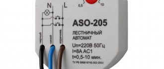
Setting up devices of this type is illustrated using the example of a timer with a digital scale of the “REV Ritter” brand, plugged into a regular power outlet. The period of validity of its temporary delay is, as a rule, limited to one day, which is quite enough for domestic conditions. Instructions for setting up such a relay include the following points:
- Plug the device into a power outlet.
- Move up all the adjusting elements (segments) aligned around the circumference of the adjustment disk.
- Move down only those that correspond to the set time.
- The center disk indicator is set to the current time.
If the segments located between the numbers 18 and 20 are shifted down, the desired load will turn on after the 18-hour interval and turn off after two hours. The design of such a semi-automatic device provides the ability to organize up to 48 work cycles (on and off) within two calendar days.
Diagram and principle of operation of an electromagnetic relay
Let's look at how this mechanism works from the inside.
- The inductor contains a movable steel armature.
- When voltage is applied to the coil, an electromagnetic field is formed around it, which attracts this armature to the coil.
- The frequency and timing of the voltage supply is electrically or mechanically controlled.
The structure of the device consists of three main elements:
- The receptive or primary is essentially the winding of the coil. Here the impulse is converted into electromagnetic force.
- Retarding or intermediate - a steel anchor with a return spring and contacts. Here the actuator is brought into working condition.
- Executive - in this part, the contact group has a direct impact on the power equipment.
Details and design
Fixed resistors can be of the type C1-4, C1-10, C1-14, C2-23, MYAT, RPM and similar ones of corresponding power. It is preferable to use a small-sized imported variable resistor R4. When using a domestic one, it should be taken into account that “our” variable resistors may have a deviation of more than 40% from the value indicated on the case, which will complicate the setup.
The author used an imported variable resistor with a resistance of 99.2 kOhm from the tuning unit to the channel from the Siesta TV-radio receiver. The axis of the resistor used is made of plastic; a polystyrene adjustment knob is attached to it.
The MYG10-471 disk varistor can be replaced with FNR-10K471, FNR-14K471, INR14D471, INR14D511. All chokes are small-sized industrial-made from computer devices.
If the resistance of the inductor winding L1 is less than 4 ohms, then a 2 W wirewound resistor must be connected in series with it; if it is more than 7...8 ohms, then the maximum power of the connected load may have to be reduced. Capacitors C1, C3 – C6 are high-voltage ceramic. Capacitor C8 is SMD, installed as close as possible to the power terminals DD1.
Oxide capacitors are imported analogs of K50-68. Capacitor C7 - film K73-17, K73-24 or an imported analogue.
The G2SBA60 diode bridge is designed for a current of 2A and a voltage of 600 V; it can be replaced with GBL06, RBV-406FI, G2SB60, or, for example, with four rectifier diodes 1N5406, KD226G, 1 N4006, KD243ZH, KD247D. These same diodes can replace diodes 1N4005, 1N4007. Instead of the FR107 diode, UF4007, FR157, FR207, FM207 are suitable. The Schottky diode SR360 can be replaced with SR306 or MUR460, UF5403, FR303G, SRP300J.
The 1SS176S diode can be replaced with any of the series 1 N914, 1 N4148, KD512, KD521, KD522.
The GZS12Z zener diode can be replaced with 1N4742A, BZV55C-12, TZMC-12 or the domestic 2S212Ts, KS212Ts. Instead of the BZV55C-18 zener diode, 1N4746A, TZMC-18 is suitable. The GZC5.1Z zener diode can be replaced with 1N4733A, BZV55C-5V1, TZMC-5V1.
You can try installing a domestic zener diode 2S151T1 in place of VD6. When installing domestic zener diodes in place of ZD1 and or VD5, you can get a non-functional design or damage powerful field-effect transistors due to overheating.
LEDs RL30-CB744D blue and RL30-DR344S red - with increased light output. Can be replaced with any similar ones, for example, from the KIPD21, KIPD40, KIPD66, L-1513 series.
One of these LEDs can replace AL307K. Instead of the PC817 optocoupler, any four-pin PC817, PS817S, PS2501-1, PC814, PC120, PC123SFH617A-2, LTV817 will do.
Transistor 2SA1266 can be replaced with any of the SS9015, BC557, KT3107, KT6112 series. Instead of KTS9013, any of BC547, SS9013, SS9014, 2SC1815, KT3102, KT645, KT6111 can work.
The main requirement for VT2 is low reverse collector current. Field-effect transistor VT1 operates without a heat sink at a load power of up to 30 W. With a load power of 16 W (incandescent lamp), the voltage drop on the open drain-source channel does not exceed 50 mV, and with a load of 60 W it does not exceed 200 mV. Instead of 2SK1118 you can install BUZ40B, IRFP450, IRF450, TSD2M450V, KP787A.
The best option to replace VT1 would be a modern field-effect transistor SPP20N60S5 or STW20NB50, MTW20N50E, SPW47N60C3. Instead of the field effect transistor SSS6N60A, SSS7N60B, SSS6N60A, SSP10N60B, P5NK60ZF, 2SK2562, P4NK60ZFP are suitable. When installing field-effect transistors, they must be protected from breakdown by static electricity.
Button SB1 is any small-sized button with freely open contacts without fixing the position with a plastic pusher. If the button has a metal clip, then it is connected to the “minus” VD1. This reduces the likelihood of a negative impact on DD1 from static discharge when the finger approaches the button pusher.
Instead of the KCD-2011 key switch, MR21, SWA206A, KCD1-101 are suitable. Instead of the TL431A chip, any one in the TO-92 package from LM431ACZ, AZ431, AN1431T will do.
Power relays - contactors
Since most of the relays discussed above are designed to switch loads with a power from hundreds of watts to ten kilowatts, additional high-power switching relays - contactors - are used to increase the switching power. With their help, you can switch a load of several hundred kilowatts, thereby expanding the capabilities of the previously discussed relays.
The use of various types of relays allows you to optimize the operation of many electrical appliances, protect against their accidental failure, and save your own life. On their basis, it is possible to create a large number of small automation systems, such as devices for maintaining an optimal microclimate, irrigation systems, automatic door opening, light switching on and off, and many others. Compact dimensions and standard dimensions of the case allow you to connect them directly to standard sockets or use ready-made electrical boxes for their installation, which significantly reduces the cost of automation in general.
Setting up analogue relays of electronic-mechanical type
Both industrial and domestic modules are in many cases equipped with electromechanical relays, which are adjusted using potentiometers. The front panel of such devices is equipped with one or more rods, which have a slot for a screwdriver blade. Around the rod, around the circumference, there is a scale installed or drawn with the markings of values that you need to focus on when setting the parameters. The slot into which the screwdriver is inserted has another function - it acts as a pointer. By turning the rod and setting it opposite certain values marked on the marking, the necessary adjustment to the desired parameter is achieved. Electronic-mechanical devices are actively used in circuits responsible for controlling ventilation systems, heating modules, and lighting devices.
Advantages and disadvantages of various implementations of the Star-Delta circuit
Before talking about the advantages of the FiF engine start relay, I will tell you about the disadvantages of other implementations of the circuit.
Nobody in new equipment implements the “Star-Triangle” circuit on a time relay, because this circuit has several disadvantages:
- Pneumatic and mechanical relays are capricious;
- For normal operation of the circuit, a second relay is needed, which must implement a pause between modes, but it is usually not installed;
- Using a universal electronic relay is identical in cost to using a specialized one, but what’s the point then?
The control circuit on the controller must contain the controller itself, which also performs other functions in the equipment. But the controller is not always present. And if there is one, then the price of the equipment and the requirements for its functionality require the installation of a frequency converter. And then the requirements for smooth engine acceleration naturally disappear.
So, in the absence of a controller, specialized Star-Delta relays are used, which fully implement the required engine starting algorithm, while having all the necessary adjustments on the front panel.
Current relay device
First, let's look at the principle of a current relay and its design. At the moment, there are electromagnetic, inductive and electronic relays.
We will disassemble the structure of the most common electromagnetic relays. Moreover, they provide the opportunity to most clearly understand their operating principle.
- Let's start with the basic elements of any current relay. It must have a magnetic circuit. Moreover, this magnetic circuit has a section with an air gap. There may be 1, 2 or more such gaps, depending on the design of the magnetic core. In our photo there are two such gaps.
- There is a coil on the stationary part of the magnetic circuit. And the moving part of the magnetic circuit is secured by a spring, which counteracts the connection of the two parts of the magnetic circuit.
- When voltage appears on the coil, an emf is induced in the magnetic circuit. Thanks to this, the moving and stationary parts of the magnetic circuit become like two magnets that want to connect. A spring prevents them from doing this.
- As the current in the coil increases, the emf will increase. Accordingly, the attraction between the moving and stationary sections of the magnetic circuit will increase. When a certain current value is reached, the EMF will be so great that it will overcome the resistance of the spring.
- The air gap between the two sections of the magnetic circuit will begin to decrease. But as the instructions and logic say, the smaller the air gap, the greater the attractive force becomes, and the faster the magnetic circuits connect. As a result, the switching process takes hundredths of a second.
It depends on the design, and can also be adjusted individually for each relay by tensioning or loosening the spring. This can be done with your own hands.
A simple scheme for beginners
Beginner radio amateurs can try to make a timer, the principle of operation of which is as simple as possible.
However, with such a simple device you can turn on the load for a specific time. True, the time for which the load is connected is always the same.
The operating algorithm of the circuit is as follows. When the button labeled SF1 is closed, capacitor C1 is fully charged. When it is released, the specified element C1 begins to discharge through resistance R1 and the base of the transistor, designated in the circuit as VT1.
For the duration of the discharge current of capacitor C1, as long as it is sufficient to maintain transistor VT1 in the open state, relay K1 will be in the on state and then turn off.
The indicated ratings on the circuit elements ensure that the load operates for 5 minutes. The operating principle of the device is such that the holding time depends on the capacitance of capacitor C1, resistance R1, current transfer coefficient of transistor VT1 and the operating current of relay K1.
If desired, you can change the response time by changing the capacitance C1.
Kinds
According to their design, time relays are divided into:
The monoblock is a completely independent device, with its own housing, built-in power supply and special sockets for connecting any equipment. Those involved in photo printing are well familiar with this type of relay.
Built-in relays are a simplified version of monoblock relays. They do not have their own housing and power supply, since they are needed in order to create more complex devices. They are used as additional elements and therefore they are placed in the same housing with other elements of the manufactured device. A classic example is a timer in a washing machine, microwave, oven, etc.
Modular (with control contact) - this type has standard dimensions and is installed on a DIN rail in the distribution panel.
In addition, time relays are also classified depending on the operating principle (how exactly the time interval is created):
- Time relay with clock mechanism. This type was the first to be manufactured and is still considered one of the most reliable, since its properties are not inferior to pneumatic devices. Their operation is practically independent of voltage power, how often it is applied, or temperature changes. In everyday life, this type of relay is found in mechanical alarm clocks, kitchen timers, and in some washing machines a mechanical program relay is also found.
- With electromagnetic retardation.
Used in circuits oriented to constant voltage. The delay is carried out by creating an auxiliary magnetic flux, regulated by changing the tension value of the return spring. The adjustable value is up to five seconds. A significant disadvantage of this type of relay is that the time delay depends on temperature changes. Electric relay - Vacuum (electromechanical). This type is used where an electrical or pneumatic signal is required to control whether the vacuum level has been reached.
- Motor. Includes motor with gearbox and electrical contact. The time delay capability ranges from 10 seconds to tens of hours.
- Relay with hydraulic or pneumatic retardation. Time intervals here are regulated by increasing or decreasing the supply of liquid and air into the working process. One of the advantages is that the slowdown does not depend on the voltage, supply frequency and temperature changes. Also, adjusting the delay is not difficult.
- Electronic relay. The most widely used type of time relay, gradually replacing mechanical analogues. The advantages of this type are its small size, weight, high accuracy, reliability and wide selection of operating programs.
Electronic relays are divided among themselves based on the timing technology:
- Digital—voltage is applied to the power supply, which causes the master oscillator to start, which then sends pulses to the counter. The latter, in turn, calculates these pulses until they are equal to the required number of pulses that is specified in the system. Then, a signal is sent to the output amplifier controlling the relay and the counter stops counting pulses. As soon as the voltage is removed from the power supply, the relay will return to its original state. Such radios are capable of delaying time for tens of hours with minimal error. The main disadvantage is the high cost.
- Analog - to delay time, a capacitor is used, to which voltage is applied when the contacts are closed. This voltage is monitored by a special device that compares it with the previously specified one. If they match, the device sends a signal so that the relay switches. The maximum shutter speed here is 10 seconds. This type is superior to digital in that it does not require precise programming and is easier to use.
On the chip
Disadvantages of the above mentioned temporary relays on transistors:
- short, unclear delay frames;
- the need to reset the capacitor charge for the next activation;
- difficulties arise in determining the duration.
The disadvantages will be partially eliminated if you integrate a microcircuit (microcontroller, abbreviated as MK) into the homemade product, which allows you to configure the pause - NE555, or similar. The initial letters of the specified MK can be LM and others. This is a time module that makes it possible to adjust the pause using a variable resistor, that is, more accurately than with assemblies (discussed above).
There are several options for making a time relay on an MK. We chose the first product based on NE555 with protection (R4), which prevents the variable resistor from being “twisted”.
Basic circuit on LM555
Turning off the relay ensures automatic switching of the resistor, only it closes based on a signal from the output of the microcircuit, after counting down the required seconds.
The designations in the diagram are deciphered in the variants we described above; we will remind you of them as we describe the stages of homemade work. R2 and 4 (if present), C1 set the duration of pauses. Activation of the “mikrik” - SB1 - closes K1.1 and after a certain interval they disengage. After this, you can press SB1 again. Delays are calculated using the equation:
Multiplication by R4 is added to the formula if such a resistor is installed. The relay is suitable for a wide range of load types, for 9…14 V.
Push-button microswitch and resistors (can be with relays):
Variables (R2) are manufactured in several standard sizes, all will fit, the nominal value is taken depending on the selected min. and max. delays:
Capacitor C2:
The time relay assembly for 555 operates from a power supply with a network transformer, through a diode bridge, capacitors, and there is no parametric stabilizer. All parts can be connected to each other on or without a platform.
Improved version
The above circuit has disadvantages: it is susceptible to interference, the relay is not deactivated if the input pulse duration exceeds the delay. The second option on NE555 is more advanced, without a transistor, resistant to interference and the like. This solution simplifies and reduces the cost of homemade products, the number of elements is reduced, the maximum output current is increased so that the relay windings can be connected directly to the output.
The homemade product is based on relay K1, connected to the output. The maximum current of NE555 exceeds 100 mA, which makes it possible to connect it directly if its winding consumes less, if more, you will need a suitable transistor. You will need VD1 - a reverse diode. Low noise immunity is a consequence of the presence of two 555 comparators, half of the pins go outside, the rest are connected to internal high-resistance resistors.
Pin operation:
- 2, 5, 6 go outside - the voltage is set to them as desired, another one remains inside, but interference is unlikely to affect the timer;
- 6 - connected to the RC circuit (as it was) - the voltage is clearly set to it;
- 5 - to be on the safe side, it is permissible to connect it to three external resistors with low resistance, which will slightly improve the noise immunity;
- 2 - standardly connected through a resistor to the “+” power supply, and then through a button to the ground (“–”). This will not create an incorrectness, since when the button is not activated, the voltage on N 2 is compared with the supply voltage, and when it is pressed, on N 2 it = 0.
If an excessively long cable goes to pin 2, it will initiate interference and create a voltage there that is not what is required. Therefore, the gap from N 2 to the button or node that creates the correct value on it is made as small as possible and a resistor is selected that “pulls up” this pin to “+” with the lowest possible resistance, but not so much that a short circuit occurs when the button is activated or when it sag to 0 voltage in this place. In the first scheme, this parameter was 100 Ohms (higher for lower electricity consumption), in the variant under consideration - 4.7 kOhms. That is, as low as possible to increase noise immunity, it is permissible to place it even lower, for example, if there is an induction furnace and similar devices nearby.
Another disadvantage is eliminated by capacitor C1, and optocoupler U1 is installed for galvanic isolation of the control circuit and relay, which will also improve noise immunity. When its LED is sharply activated and the transistor is opened, the voltage on the collector quickly sags - a low value is created on N 2 for a short time. When charging of capacitor C1 is complete, the value becomes equal to the power supply parameter, and even if the transistor is always open, the pulse at the input to the circuit is still short, the relay is deactivated after the pause period has expired.
After closing the transistor C1 with a short pause will discharge through R1 and 2 (resistors), it will be possible to activate the timer again.
The time relay circuit itself is implemented on a board made of double-sided fiberglass, on one side there are tracks for all elements, the other is left empty, 0 (minus) is soldered to it, which is connected to pin 1 of the 555 controller, which will further enhance stability. It is advisable to move the release contacts as far as possible from the circuit; if possible, then solder them onto a separate board (not the same one as 555).
Other options on NE555
The following diagram is much simpler and clearer than the previous ones. Can be set to either on or off.
As you can see, there are 2 buttons:
- launch - “start”;
- return to the beginning - “stop”.
Control - resistor R1 and cond. C1, the pause depends on their parameters, in this case its range is 2 seconds. - 3 min. Power supply - 12 V.
An example of a working homemade product
The circuit is powered by 9 V. Activation - the “Start” button, the HL1 LED lights up, after the interval - HL2. The delay is adjusted using a variable on the timer. This handicraft product is used by the user to heat mirrors in the car. If you build in a power relay, you can connect anything.
The next option is a little more complicated, but in general it is also elementary:
Type of finished assembly (there are similar factory modules):
Based on TL431
Elements (characteristics on the diagram):
- resistors - 3 pcs. (on diagram R);
- TL431 controller;
- "mikrik";
- capacitor (C1, selected experimentally);
- e/m relay (executive unit).
One contact of the relay is connected in parallel to the “micrik”, to it - “+” from the power supply; the second is output to a 100 Ohm resistor, also connected to resistances. Pins 2 and 3 of the microcircuit are connected to a 100 Ohm resistor and a diode. The last contact of the timer is to the semiconductor with the executing unit (electronic relay). The disadvantage of the power supply is a resistance of 510 Ohms. Feature of the circuit: the capacitor is discharged automatically; additional activation of the SB1 microphone is not required.
Timer for daily activation on CD4060B, CD4001 chips
The circuit is assembled on the basis of 2 pulse generators, covering a periodicity in the range of 24 hours. It also includes a trigger and an output switch with a relay. Power supply - “charging” a smartphone, 5 V cell phone. You can provide a backup source (in the considered version there is none). The generators are built on CD4060B microcircuits with a 14-bit binary counter (there are no pins from 1–3 and 11 digits) and 2 inverters (one connected to the counter input) for a multivibrator circuit, placed in series.
The multivibrator frequency is set by RC circuits C1-R2 and C4-R7, and by selecting the resistances of resistors R2 and R7, a 24-hour pulse frequency is set. Make sure that a logical one appears at pin 14 after 2 minutes. 50 sec. after pressing S1 (S2). Then the resistance is selected more precisely, making this interval equal to 1 minute. 15 seconds, at the last stage daily adjustment is carried out.
Tips for installation and setup
Before installation, decide in advance which network you will work on (for example, three-phase or single-phase). It is also important to know exactly which load will require switching on or off. Once you know exactly what you want, feel free to go to the store and buy the appropriate device. Before you install the device and turn off the power to the lighting, check whether the device is working correctly: connect the cord with the plug to it and set the minimum time for operation. Check the voltage at the output contacts with a tester. When installing to a DIN rail, tighten the bolts tightly to prevent the unit from heating up, causing damage, or even causing a fire. Remember that the maximum humidity at which the device can work properly is no more than 80%, and the temperature is from 10-50 degrees.
Settings
- Setting the timer in the device depends on what type of device is in front of us. If we are dealing with a mechanical relay, then setting it up simply consists of switching positions according to the inscription.
- In the electronic one, there is a menu through which all settings are made. As a rule, it begins with setting the day of the week and the current time, and then programming the device itself.
- If this is an electromechanical relay, then it is adjusted using special measuring instruments - potentiometers.
Connection diagram
As a rule, connecting a relay eliminates the use of complex circuits. The main thing, as was said, is to know what load will be required.
Let's consider the simplest scheme:
- Fix the device strictly vertically and tightly enough to the wall.
- Remove the cover and ground the relay.
- Connect the electrical network to the contacts (see picture)
- Contacts 1 and 2 are designed to supply voltage of 220 Volts.
- Designation 4 - used to supply phase from the electrical panel and can be switched with 3 and 5.
- 4 and 5 are normally open, while 3 and 4 are normally closed.
Complete set of circuit elements
To make such a timer operating at 12v voltage, you need to correctly prepare the circuit parts.
The elements of the scheme are:
- diodes VD1 - VD2, marked 1N4128, KD103, KD102, KD522.
- The transistor that supplies 12v voltage to the relay is designated KT814A or KT814.
- Integral counter, the basis of the operating principle of the circuit, marked K561IE16 or CD4060.
- LED device ARL5013URCB or L816BRSCB series.
It is important to remember here that when making a homemade device, you must use the elements indicated in the diagram and follow safety rules.
Settings
Setting the operating time parameters for each shutdown timer is quite individual. Generally speaking, control mechanisms are often represented by corresponding buttons next to the operation indicator on its front side or rotary controls. With the latter, there is a nuance of convenience - they can be designed to be moved using a flat-head screwdriver. That is, you cannot turn them by hand. You need to take the tool, insert it into special slots and use it to set the values.
In addition to the already mentioned configuration methods, in relation to microprocessor relays, it is possible to set a program with time intervals of operation using a third-party computer connecting to the device via cable or Wi-Fi.
Time relay controllers with Wi-Fi connection:
Which time relay is better to buy
One of the main criteria for choosing such equipment is the permissible frequency of operation. There are daily and weekly time relays.
The first type has a simpler design and supports a small number of cycles for use within 24 hours. Weekly timers have flexible adjustment and large memory. They can be configured to change program mode daily.
The convenience of control is affected by the type of relay. Digital models are equipped with LCD displays and microprocessors - they are distinguished by high precision and switching speed.
Mechanical ones use synchronous or quartz drive technology. They are extremely easy to use and cost less than their electronic counterparts.
You should also determine the future operating conditions and the list of equipment on the network. This will help calculate the maximum AC power of the connected appliances. The indicator should not exceed the permissible value for the relay.
We advise you to pay attention to the specified protection class of the device.
To select the optimal model, it is important to know what environmental factors will affect the device, predict the humidity level and temperature conditions
When using the relay indoors, a protection class higher than IP20 is not required.
Not all time relays are compatible with household electrical appliances. We recommend that you familiarize yourself with the voltage of the device before purchasing. Many models on sale are designed to operate in circuits designed for 12, 42, 127 V, etc.
Recommendations: 12 best manufacturers of sockets and switches
14 best switches
15 best voltage stabilizers
Books on the subject of engines
For those who want (as my boss says) to “plunge into the problem,” I post good books on engines and electrical engineering in general for free download and review.
• V.L. Likhachev. Asynchronous electric motors. 2002 / The book is a reference book that describes in detail the design, operating principle and characteristics of asynchronous electric motors. Reference data is provided for engines of previous years of production and modern ones. Electronic starting devices (inverters), electric drives are described., djvu, 3.73 MB, downloaded: 7136 times./
• Bespalov, Kotelenets - Electrical machines / Transformers and electrical machines used in modern technology are considered. Their decisive role in the generation, distribution, conversion and utilization of electrical energy is shown. The basic theory, characteristics, operating modes, examples of designs and applications of electrical generators, transformers and motors are given., pdf, 16.82 MB, downloaded: 2317 times./
• MM. Katzman - Electrical Machines / Some say this is the best textbook on electrical engineering. The book discusses the theory, principle of operation, design and analysis of operating modes of electrical machines and transformers, both general and special purpose, which have become widespread in various branches of technology., pdf, 22.12 MB, downloaded: 2061 times./
• Electromash motor catalog / Asynchronous electric motors with squirrel-cage rotor - manufacturer’s catalog, pdf, 3.13 MB, downloaded: 1376 times./
• VEMZ engines catalog / Engine parameters and catalogue, pdf, 3.53 MB, downloaded: 1181 times./
• Dyakov V.I. Typical calculations for electrical equipment / Practical calculations for electrical equipment, theoretical information, calculation methods, examples and reference data., zip, 1.53 MB, downloaded: 2515 times./
• Karpov F.F. How to check the possibility of connecting several motors to the electrical network / The brochure shows the calculation of the electrical network for voltage fluctuations during the start-up and self-starting of asynchronous motors with squirrel-cage rotor and synchronous motors with asynchronous starting. The conditions under which starting and self-starting of engines are permissible are considered. The presentation of calculation methods is illustrated with numerical examples. The brochure is intended for qualified electricians as a guide when choosing the type of electric motors connected to a municipal or industrial power supply network., zip, 1.9 MB, downloaded: 1640 times./
• Operating manual for asynchronous motors / This manual contains the most important instructions for transportation, acceptance, storage, installation, commissioning, operation, maintenance, troubleshooting and troubleshooting for electric motors produced by Elektromashina. The operating manual is intended for three-phase asynchronous electric motors of low and high voltage series A, AIR, MTN, MTKN, 4MTM, 4MTKM, DA304, A4., pdf, 7.54 MB, downloaded: 2540 times./
• Catalog of AIR engines / Catalog of AIR engines - power from 0.12 to 315 kW; rotation speed 3000, 1500, 1000, 750 rpm; mains voltage 220/380 V, 380/660 V;, pdf, 1.07 MB, downloaded: 1044 times./
• Lomonosov, V.Yu.; Polivanov, K.M.; Mikhailov, O.P. Electrical engineering. / Lomonosov, V.Yu.; Polivanov, K.M.; Mikhailov, O.P. Electrical engineering. One of the best books on the basics of electrical engineering. The presentation begins with the very basics: it explains what voltage, current and resistance are, provides instructions for calculating the simplest electrical circuits, and talks about the relationship and interdependence of electrical and magnetic phenomena. Explains what alternating current is and how an alternating current generator works. It describes what a capacitor is and what an inductor is, what their role is in alternating current circuits. It is explained what three-phase current is, how three-phase current generators are designed and how its transmission is organized. A separate chapter is devoted to semiconductor devices: it talks about semiconductor diodes, transistors and thyristors; on the use of semiconductor devices for rectifying alternating current and as semiconductor switches. The achievements of microelectronics are briefly described. The last third of the book is entirely devoted to electrical machines, units and equipment: chapter 10 deals with direct current machines (generators and motors); Chapter 11 is devoted to transformers; AC machines (single-phase and three-phase, synchronous and asynchronous) are described in detail in Chapter 12; switches, electromagnets and relays are described in Chapter 13; Chapter 14 deals with electrical diagramming. The last, chapter 15, is devoted to measurements in electrical engineering. This book is a great way to learn the basics of electrical engineering, to understand the fundamental principles of the operation of electrical machines and units., zip, 13.87 MB, downloaded: 2653 times./
Another manual on motors: • Starting and protecting AC motors / Starting and protecting AC motors. Starting and braking systems for AC motors. Protection devices and fault analysis of AC motors. Guide to selecting protection devices. Manual from Schneider Electric, pdf, 1.17 MB, downloaded: 2042 times./
That's all, nothing more to say. I hope I explained the topic in detail. I look forward to questions and fair criticism in the comments!
Relay testing
Relay testing
Electronic devices operate on the basis of digital impulses. Modern devices have high-performance microprocessors. Typically, the RF is designed for switching inductive or non-inductive loads. To configure a digital type device, you will need to enter the required time parameters using the function keys. The possibility of wide customization allows you to set not only seconds, but also days of the week.
The purpose of testing is to understand the design and operating principle of a time relay. The device is checked when switched on again in the following sequence.
- External inspection and mechanical inspection.
- Checking the operation of the spark arresting circuit.
- Testing the rectifier device.
- Determination of the current resistance of the winding circuit.
- Checking the voltage during operation and return.
- Response time control.
Testing of the main parameters is carried out using a special device. When inspecting the mechanical part, corrosion and contamination are revealed. Check the movement and balancing of moving parts, the condition of axes and springs, the tightening of screws and axial play.
An important point is to check the insulation strength. Voltage is applied alternately to all bases and clamps. The insulation must withstand a voltage of 1000 V at an alternating current frequency of 50 hertz.
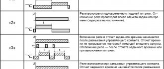
Operating principle of a time relay
The general principle of operation of a time relay is to form a time delay for turning on, off or switching control groups of contacts. The implementation of the delay depends on the design features of the device. The general differences in different types of relays lie in the switching of the executive part. Based on this feature, two groups of relay devices are distinguished:
- with shutdown delay;
- with switch-on delay.
Many relays allow you to change the type of switching or have both options.
The principle of timing and contact control depends on the design of the relay, but the general operating algorithm is as follows:
- upon startup, a contact group is activated, organized in accordance with the type of switching (for a time relay with a turn-off delay, the contacts close);
- at the same time, the time delay mechanism is cocked (the clock generator in electronic devices is started);
- after a specified interval, the contact group changes its state to the opposite.
A three-position relay has a more complex operating algorithm. The sequence of work is as follows:
- The circuit is open.
- Start. The circuit closes and the countdown begins.
- The countdown is over. The circuit is closed.
In cyclic devices, the above sequence is repeated many times.
The countdown is started manually or automatically by directly closing the power supply contacts or through an electromagnet acting on the mechanism.
A time relay with a switch-on delay works similarly.
Where can I buy
Of course, you can purchase devices as quickly as possible in the nearest specialized store. The optimal option, in terms of price-quality ratio, remains purchasing from the AliExpress online store. Mandatory long waits for parcels from China are a thing of the past, because now many goods are in intermediate warehouses in destination countries: for example, when ordering, you can select the “Delivery from the Russian Federation” option:
| Time relay module on 555 timer | Electronic time relay GEYA with delay, 16A | Digital time relay module |
| Multifunction time relay, 10 functions | Digital timer, programmable for 7 days, 220V | Programmable digital timer SINOTIMER, 16A |
Purpose and types
A time relay provides the ability to set a specific time interval necessary for the operation of electrical equipment. It is often used in cases where various devices are expected to automatically turn on after a certain period of time.
In everyday life, time relays are used to save electricity. By automatically turning on and off household appliances and lighting, the population significantly saves their budget. In addition, this device is in demand among consumers due to its long service life, as well as practicality in use.
A cyclic type device triggers a signal after a set time period. The original version of this type was mechanical. It interacted with the contacts through a programmed motorized drum. When microprocessors appeared, relays began to have different range criteria. Cyclic relays are mostly used in street lighting.
The intermediate type provides a temporary delay when connecting an electrical appliance at a set moment. Such a delay is necessary for the correct and correct operation of electrical devices that have a complex mechanism. In turn, intermediate relays are divided into electromagnetic relays; pneumatic devices; devices with a clock mechanism; electronic relays; as well as motor relays.
Block relays are used in areas of narrow specialization, for example, time delay of photo printing. The block device has a built-in power supply and is installed as an independent device.
The embedded device does not have a housing or its own power source. A relay is part of a more complex mechanism. It is used as an auxiliary element, and has a common body with other elements. The most common example is an automatic washing machine.
Modular devices are similar to block varieties. Often they are installed in distribution panels on a DIN rail.
Electromagnetic
This type is used only in networks with direct current. The relay is equipped with a short-circuited winding similar to a copper sleeve. The time delay occurs due to this sleeve, which prevents the increase in magnetic flux and the activation of the main relay armature. The device can be installed for a time period of five seconds. These types are used in electric drives for the purpose of accelerating or braking them.
Electromagnetic relay
Electronic
Electromagnetic devices have a time delay programming function. Analog and digital types are available. The device controls processes in electronic circuits, counts a set number of pulses, and regulates the discharge and charge of capacitors. Such devices are widely used in everyday life.
Pneumatic
The relay is called pneumatic because it contains a pneumatic cataract in its mechanism. By means of a special adjusting screw, the diameter of the hole that absorbs air changes, resulting in a time delay. Such a device can be programmed for a sixty-second delay. This product can be used for automatic control of electrical equipment, as well as for controlling an electric drive, its acceleration and braking.
Motor
These types are used to protect overhead lines when they are reconnected. The main element of this device is a synchronous motor, which operates using an alternating current electrical network with a frequency of 50 Hertz. In addition, the relay mechanism includes an electromagnet, through which the motor and gearbox are coupled. The device is capable of producing a time delay from ten seconds to several hours.
With clock mechanism
This relay is based on a spring. The electromagnet included in the design drives this spring into action. The required time is set on a special scale, after which the relay contacts close. The time period can be set from 0.1 to 20 seconds.
Time relay with clock mechanism
Example of installation in a steam boiler
So why did I go to the store to buy this relay?
Now there will be a terrible story. The fact is that at our enterprise in the boiler room there is an Italian steam boiler (steam generator), which provides steam for the technological process and for heating.
I upgraded this boiler, about which there was already an article on the blog Using a soft starter.
One Saturday in March, the engineer on duty called me and said that we had an emergency - the fan motor on the boiler did not turn on. More precisely, it launches into “Star”, but does not go to “Triangle”. Accordingly, the air pressure in the burner does not reach the required value, and the boiler “goes into error.”
Here's the engine:
Motor with star-delta connection circuit
Engine nameplate that switches from Star to Delta
Connecting the motor in a boron box:
Connecting the motor in the terminal box
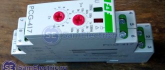
The culprit of the emergency situation, when the premises were left without heating and the enterprise without production, turned out to be a time relay for starting the Siemens Sirius 3RP1574 engine. This relay worked for more than 8 years, and then it was done.
Siemens time relay for the Star-Delta engine starting circuit, top view, on the supply contacts
The “old” relay was less functional than the model from F&F - the delay time range is only from 1 to 20 s, there is no separate connection of internal relay contacts, and there is no adjustment of the switching time.
Siemens timing relay for Star-Delta motor starting circuit
The time setting was 9 s. Video of how it happened:
Of course, there was a controller in the boiler, but this controller is not a simple one, but a specialized one for boilers, in which all European safety standards are met. And no one even thought about using it to control the start of the burner engine.
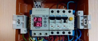
Instead of a time relay for starting the Siemens Star-Delta engine, an F&F PCG-417 relay was installed.
The photo below shows the operation of this relay in “Star” mode. Contactors CV (common, KM1) and CVS (Star, KM2) are switched on, the red indicator is flashing:
Switching on relays and contactors in Zvezda
Next, “Triangle” is turned on. Contactors CV (common) and CVT (Triangle, KM3) are turned on, the red indicator lights up steadily:
Switching on relays and contactors in Triangle
The same thing is in the video:
The video shows that the engine does not have time to accelerate in 5 seconds, so the time was increased.
A closer look at the front panel of the relay. The regulator is set to 10 s:
Switching on the star-delta time relay F&F PCG-417
Everything worked. No more than 2 hours passed from the moment of purchase to the moment of starting the boiler. At the time of writing, the FiF time relay has been operating in the boiler burner for more than 1.5 years without failure.
Where and how it is used
A time relay is used in electrical networks when it is necessary to perform a certain task after a specified time interval. There are many particular examples of such application.
An important point is the specific type of device and its parameters, which largely determine the exact scope of application. For example, electromagnetic radios are used to start large engines.
Electronic ones are often used in domestic settings to perform small tasks, such as turning on the irrigation in the area or the heating boiler to warm up, or turning off the lighting around the house after dawn.
In addition, they are used to control the lighting of advertising signs or building facades, the operation of lawn watering pumps and climate control systems, and many other tasks.
Answers to frequently asked questions
At the end of the article we will answer some of the most frequently asked questions.
Question.
Which option is preferable to a 12 V relay and an intermediate 220 V relay or one immediately designed for high voltage?
Answer.
The first option
is safer
when setting up, the second is easier to install.
Question.
Which relay is preferable, mechanical or electronic?
Answer.
Mechanical ones are cheaper, electronic ones are superior in
reliability and functionality
.
Question.
Are imported devices more reliable?
Answer.
Russian standards are stricter than foreign ones, so it is preferable to choose domestic devices.