For complete instructions on grounding and lightning protection for a private home (in pictures), see a separate page.
Today, almost every country house is equipped with electrical appliances. The safety of their operation is ensured by connecting the electrical equipment installed in the premises to a grounding device. Properly performed protective grounding will eliminate the possibility of electric shock to people and prevent the failure of household appliances and complex technical devices from the effects of overvoltages if they are protected by an SPD. The choice of connection diagram depends on various factors. In a private house, unlike an apartment building, grounding can be done independently. This instruction will help you figure out how to connect it.
The main elements of the grounding connection diagram for a country house and the rules for their implementation
The grounding connection diagram in a country house is as follows: electrical appliance - socket - electrical panel - grounding conductor - ground loop - ground.
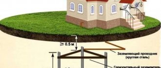
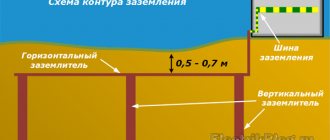
The connection begins with the installation of a grounding device in the local area in accordance with the rules defined in Chapter 1.7 of the PUE, 7th edition. The ground electrode is a metal structure that has a large contact area with the ground. Designed to equalize the potential difference and reduce the potential of grounded equipment in the event of a short circuit to the housing or the appearance of excess voltage in the electrical network. The design and depth of its installation is determined based on the soil resistance in the area (for example, dry sand or wet black soil).
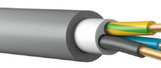
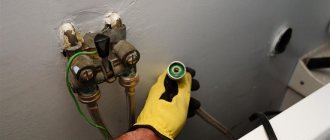
From the grounding device (grounding) made on the site, we lay a grounding conductor, which is connected to the main grounding bus using a bolted connection, clamp or welding. We select a conductor with a cross-section of at least 6 mm2 for copper and 50 mm2 for steel, and it must meet the requirements for protective conductors specified in Table 54.2 of GOST R 50571.5.54-2013, and for the TT system have a cross-section of at least 25 mm2 for copper. If the conductor is bare and laid in the ground, then its cross-section must correspond to that given in table 54.1 of GOST R GOST R 50571.5.54-2013.
In the electrical panel, the grounding conductor is connected through a grounding bus to protective conductors laid to sockets that have a grounding contact and other electrical receivers in the house. As a result, each electrical appliance is connected to the grounding system.
Errors when installing memory
Typical disadvantages often encountered in practice include:
- Use as a contour of metal fences or masts. Current resistance is not taken into account and creates the risk of severe electric shock to people in the event of an accident in the system.
- Connecting the circuit directly to the housing of electrical appliances, bypassing the grounding bars in the panel.
- Installation of separate switches in the neutral conductor. If the device fails, electrical appliances may become energized. Sometimes the neutral wire contact is not strong. The consequences are the same.
- Use of products of smaller cross-section or thickness for grounding conductors. Such electrodes quickly fail under the influence of corrosion.
- Use as a grounding conductor for the working “zero”. There is an increased likelihood that the system will be energized.
- Location of horizontal grounding conductors on the surface of the earth. In the event of an accident, the affected area will increase.
- Ground connection to the heating pipe. It is impossible to say which direction the stray currents will take, since the situation in the neighboring apartment is unknown. The likelihood of electric shock to strangers increases.
Upon completion of installation work, the system is checked. Attention is drawn to the value of current dissipation resistance. To carry out this work, it is advisable to involve a specialist with the appropriate equipment.
Dependence of the grounding connection diagram on the grounding loop
If the power line pole is re-grounded, then the grounding connection diagram in a country house is carried out using the TN-CS or TT systems. When the condition of the networks does not cause concern, re-grounding of the line should be used as the grounding device for the house and the house should be connected in accordance with the TN-CS grounding system. If the overhead line is old, or the quality of repeated grounding is questionable, it is better to choose a TT system and equip an individual grounding device in the local area.
For a grounding device, first of all, natural grounding conductors should be used - third-party conductive parts that have direct contact with the ground (water pipelines, well pipes, metal and reinforced concrete structures of a country house, etc.). (see clause 1.7.54, 1.7.109 PUE 7th edition).
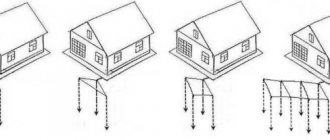
If there are none, we create an artificial grounding device using vertical or horizontal electrodes that we dig into the ground. The choice of grounding configuration mainly depends on the required resistance and the characteristics of the local area.
If there are none, we create an artificial grounding device using vertical or horizontal electrodes that we dig into the ground. The choice of grounding configuration mainly depends on the required resistance and the characteristics of the local area.
It is most effective to use if the soil on your site is composed of loam, peat, water-saturated sand, and water-saturated clay. The standard length of the rods ranges from 1.5 to 3 m. When choosing the length of vertical electrodes, we proceed from the water saturation of the host rocks in the area. Vertical ground electrodes buried in the ground are combined with a horizontal electrode, for example, a strip, and to minimize shielding they are located at a distance commensurate with the length of the pins themselves.
The design of the grounding device is recommended to be located at a distance of one meter from the foundation of the building (see clause 1.7.94 of the PUE, 7th edition).
How to make grounding in an apartment if there is none?
The most optimal solution to the problem is to have a ready-made terminal in the distribution panel. Then it is enough to provide a grounding wire at the wiring installation stage and connect it to the existing building’s own circuit or to the grounding from the line.
1. Installation of RCD.
If the electrical wiring of the riser at the construction stage did not provide grounding for apartments, then a protective device can be connected to protect against potential contact with the housing of electrical appliances. In an apartment, an RCD is relevant for powerful devices with a metal body (water boilers, washing machines, dishwashers, etc.), so it can be connected selectively. However, if there is no individual grounding wire, the RCD will of course be triggered by leakage currents, but you will not be able to rebuild full-fledged protection. Because of this, this method may be suitable as a temporary solution until a ground loop is installed for the entire house or apartment.
Dependence of the connection diagram on the type of grounding system
Grounding of residential buildings is carried out using the following systems: TN (subsystems TN-C, TN-S, TN-CS) or TT. The first letter in the name indicates the grounding of the power source, the second - the grounding of open parts of electrical equipment.
The subsequent letters after N indicate the combination in one conductor or the separation of the functions of the zero working and zero protective conductors. S - zero working (N) and zero protective (PE) conductors are separated. C - the functions of the neutral protective and neutral working conductors are combined in one conductor (PEN conductor).
Electrical safety is fully ensured when a decrease in the resistance of the ground electrode does not entail an increase in the ground fault current. Let's consider how the grounding connection diagram depends on the electrical network system implemented at the facility.
Grounding system TN-S
Figure 1. TN-S system
At facilities equipped with an electrical network using the TN-S system, the neutral working and protective conductors are separated along the entire length, and in the event of a phase insulation breakdown, the emergency current is discharged through the protective PE conductor. RCD devices and automatic circuit breakers, which react to the occurrence of current leakage through the protective zero, disconnect the network with the load.
The advantage of the TN-S grounding subsystem is the reliable protection of electrical equipment and people from damage by emergency current when using electrical networks. Due to this, this system is considered to be the most modern and safe.
To carry out grounding using the TN-S system, it is necessary to lay a separate grounding wire from the transformer substation to your building, which will lead to a significant increase in the cost of the project. For this reason, the TN-S grounding subsystem is practically not used for grounding private sector facilities.
TN-C grounding system. The need to switch to TN-CS
Figure 2. TN-S system
Grounding using the TN-C system is most common for old residential buildings. The advantage is that it is cost effective and easy to implement. A significant drawback is the absence of a separate PE conductor, which eliminates the presence of grounding in the sockets of a country house and the possibility of equalizing potentials in the bathroom.
Electric current is supplied to suburban buildings via overhead lines. Two conductors are suitable for the structure itself: phase L and combined PEN. It is possible to connect grounding only if there is three-wire wiring in a private house, which requires converting the TN-C system to TN-CS by separating the neutral working and neutral protective conductors in the electrical panel (see clause 1.7.132 of the PUE, 7th edition) .
Grounding connection using the TN-CS system
The TN-CS grounding subsystem is characterized by the combination of the neutral working and neutral protective conductors in the area from the power lines to the entrance to the building. Grounding according to this system is quite simple in technical design, due to which it is recommended for wide use. The disadvantage is the need for constant modernization in order to avoid breakage of the PEN conductor, as a result of which electrical appliances may be exposed to dangerous potential.
Let's consider the grounding connection diagram in a country house using the TN-CS system using the example of a transition to it from the TN-C system.
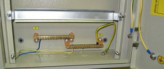
Figure 3. Main distribution board diagram
As already noted, to obtain three-wire wiring, it is necessary to correctly separate the PEN conductor in the distribution panel of the house. We start by installing a busbar into the electrical panel, ensuring a strong metal connection with it, and connecting the combined PEN conductor coming from the side of the power line to this busbar. We connect the PEN bus with a jumper to the next installed PE bus. Now the PEN bus acts as the bus of the zero working conductor N.
Figure 4. Ground connection diagram (transition from TN-C to TN-CS)
Figure 5. TN-CS ground connection diagram
Having completed the indicated connections, we connect the distribution panel to the grounding device: from the grounding device we connect a wired PE bus. Thus, as a result of a simple modernization, we equipped the house with three separate wires (phase, neutral protective and zero working).
Electrical installation rules require re-grounding for PE and PEN conductors at the input to electrical installations, using, first of all, natural grounding conductors, the resistance of which at a power supply voltage of 380/220 V should be no more than 30 Ohms (see clause 1.7 .103 PUE 7th edition).
Grounding connection according to the TT system
Figure 6. TT system
Another option for the circuit is to connect the grounding of a country house using a TT system with a solidly grounded neutral of the current source. The exposed conductive elements of the electrical equipment of such a system are connected to a grounding device that has no electrical connection with the neutral grounding electrode of the power source.
In this case, the following condition must be met: the value of the product of the response current of the protection device (Ia) and the total resistance of the grounding conductor and grounding conductor (Ra) should not exceed 50 V (see clause 1.7.59 of the PUE). Ra Ia ≤ 50 V.
To comply with this condition, “Instructions for the installation of protective grounding and potential equalization in electrical installations” I 1.03-08 recommends using a grounding device with a resistance of 30 Ohms. This system is quite in demand today and is used for private, mainly mobile buildings, when it is impossible to provide a sufficient level of electrical safety with the TN system.
Grounding according to the TT system does not require separation of the combined PEN conductor. We connect each of the individual wires approaching the house to a bus isolated from the electrical panel. And the PEN conductor itself, in this case, is considered to be the neutral wire (zero).
Figure 7. TT ground connection diagram
Figure 8. Connection diagram for grounding and RCD according to the TT system
As follows from the diagram, the TN-S and TT systems are very similar to each other. The difference lies in the complete absence of an electrical connection between the grounding device and the PEN conductor in the CT, which, in the event of the latter burning out from the power source, guarantees the absence of excess voltage on the body of electrical devices. This is the obvious advantage of the TT system, providing a higher level of safety and reliability in operation. The only disadvantage of its use is its high cost, since to protect users from indirect contact, it is necessary to install additional protective power supply devices (RCDs and voltage relays), which, in turn, requires testing and certification by an energy supervision specialist.
Final recommendations
Now you know how to properly ground in an apartment or house. Let's summarize:
- Grounding is necessary to protect a person from possible electric shock in an apartment or private house.
- The safest option is when the body of the electrical appliance is grounded and an RCD is installed.
- In an old housing stock, it is better not to take risks and replace the old wiring with three-core VVG NG cables and use protective automatics, while trying to resolve the issue of installing a common house grounding loop.
- In a new housing stock, protective grounding can be organized at the stage of electrical installation using three-wire wires, grounded sockets and automatic protective equipment. When a phase hits the device body, the circuit breaker should trip. When touching live parts, the RCD should trip.
- Make a separate ground loop for the metal bathtub and sink, metal pipes, washing machine, hob and oven.
- In a private house, organize a circuit with a closed ground loop of three pins in the ground, connected to each other and to the shield by an earth bus.
- Be sure to check that the grounding is working correctly.
Design and purpose of grounding devices
Such structures are divided into working and protective devices.
- The worker is used to organize the safe operation of industrial units. Also common in private households.
- A protective grounding system is required for electrical networks in the residential sector.
Installation of a grounding device (GD) is required in accordance with the Rules for the Construction of Electrical Installations and the Rules for the Operation of Consumer Electrical Installations.
People touching live parts exposed as a result of improper operation of electrical equipment, design defects, deterioration of insulation and other reasons is common. Poor-quality design of the charger and its installation can lead to serious consequences for people: electric shock, burns, disruption of the heart and other human organs, electric shock often leads to amputation of limbs, disability and even death.
The grounding system consists of external and internal parts, which are joined in the electrical panel. An external grounding device consists of a complex of metal electrodes and conductors that drain emergency current from electrical equipment into the ground in places that are safe for people. The electrodes are called ground electrodes. Electrical conductors are grounding conductors; they are pins 1.5 m long and 1 mm in diameter.
They are manufactured industrially from copper or copper-plated steel. Their main advantage is increased current conductivity. They are driven into the ground with hammers or sledgehammers to a depth of 50 cm; contact with the ground must be as strong as possible, otherwise the structure’s ability to drain current will deteriorate.
The simple design is made from a single electrode. Used in lightning rods or to protect remote objects and equipment. In individual farms, preference is given to multi-electrode devices. They are placed in one row and are called linear memory profiles. The standard chain length is 6 meters. They are connected to each other using brass couplings; the fastening is threaded; welding is not recommended. Grounding conductors are installed through terminals. Twisting and soldering of cores are excluded.
A device such as a ground loop (closed version) is still common. It is constructed at a distance no closer than 1 meter and no further than 10 meters from the house. Placed in a trench in the form of an equilateral triangle. Side length 3 m, depth – 50 cm, width – 40 cm. Grounding conductors are driven into the corners. The same operation is performed with other vertical electrodes (no more than five units). Grounding conductors in the lower supporting part are welded to horizontal products.
They are made of copper, copper or zinc coated steel angle (5 mm flange, 40 mm strip). A standard stainless steel angle of any profile is often used. The products are not painted, as in this case the electrical properties will deteriorate due to weakened contact with the ground.
The design of the circuit is simple; you can do it yourself. But the work is simplified when using ready-made grounding devices on the market, complete with grounding wires. Financial losses will be recouped through the use of high-quality materials that are resistant to corrosion and have a long service life.
Housing installation
When installing outside the home, it is recommended to use steel electrical panels (No. 1 in the image), which can be locked. The degree of protection from dust or moisture must be at least IP54.
Typically, the shield is mounted at the boundary of the site, for example, on a power line support, a building wall or a fence. Depending on the ease of access to it for inspectors. It is best to bring wires and cables inside for switching, preferably from below, using sealed leads. This way you will ensure maximum tightness and significantly protect the electrical installation as a whole.
All modern switchboard equipment is mounted on DIN rails. Make sure that the shield you purchase has them installed or included. Otherwise, you will have to buy an additional DIN rail.
Counter SO-EU10 - technical characteristics
Good day, friends! We received a SO-EU10 meter, according to reviews they say that the meter is reliable and inexpensive, and is also not fussy in terms of operation. Today we’ll look at what technical characteristics this electric meter has and when you need to check it.
SO-EU10 is a single-phase, single-tariff device for metering active electrical energy in alternating current circuits. Designed for indoor use. Suitable for apartments, country houses and garages with acceptable energy consumption.
The meter has a mechanical counting mechanism - a drum dial, which shows the number of kilowatts wound.
A ring rotates in the counter; the number of revolutions per unit of time is proportional to the amount of energy consumed.
Specifications
Let's consider the main technical characteristics that may be useful when choosing an electric meter or during its operation.
- The ambient temperature in which the meter can reliably keep records is from -22 to +55
- Rated network voltage 220 Volts
- Base and maximum current 10/40 A.
- Mains frequency 50 Hz
The meter constant for determining the accuracy of electricity consumption by rotating the induction ring is 600 revolutions kilowatt/hour. Based on the rotation speed, you can determine for yourself what the current energy consumption is.
Accuracy class
The meter belongs to class 2 measurement accuracy. In more advanced meters, the accuracy class of the device can be 1 or 0.5. For small home energy consumption, this value does not play a big role.
Calibration interval
The verification interval of SO-EU10 is 16 years. The countdown begins from the day of the first verification at the factory, so count correctly and study the passport before putting it into operation. The verification is carried out by metrologists, who will have to put the appropriate mark in the meter’s passport. If you don’t have a passport, verification may be denied.
Betar sgbm 1.6 - characteristics and battery replacement
Life time
The service life of the SO-EU10 electric meter is 32 years. This is the average service life of this meter.
Also, in addition to the service life, there is a characteristic time between failures; for this meter this value is 140,000 hours of continuous operation, or almost 16 years.
For some single-phase, single-tariff induction-type meters, the time between failures almost coincides with the service life. The manufacturer provides a standard warranty of 24 months.
How to take readings
When taking readings from the SO-EU10 meter, everything is done in the same way as in other single-tariff meters, all numbers are rewritten from left to right, up to the comma or a highlighted number. The total counter has 6 digits (bit size/value). SO-EU10 keeps track of both whole kilowatts and fractions, 5 digits from left to right up to the decimal point of the number of kilowatts, and we rewrite them when removing them. The rightmost figure is a fraction of a kilowatt; there is no need to rewrite it.
Connection diagram
To install and connect the meter, you can use the connection diagram for conventional single-phase electric meters; there are no special subtleties in installing this meter.
More detailed characteristics and user manual can be found in the meter passport. Try not to lose it as it will be needed during operation for verification. Below we attach the passport for SO-EU10. Passport SO-EU10.PDF
Tags: , automatic, boiler, sconce, view, harm, choice, house, , grounding, ground, replacement, insulation, like, kilowatt, computer, circuit, , magnet, marking, installation, multimeter, voltage, neutral, nominal, connection, rule, wire, project, start, , work, size, calculation, relay, repair, row, light, lamp, system, resistance, term, circuit, ten, type, current, transformer, , phase, photo, shield, electricity, electrical panel
Which is better - homemade contours or a purchased kit?
To equip the grounding of a country house, you can buy a ready-made device kit. This will allow you to quickly install the structure, often without even the use of welding equipment. To connect individual elements, manufacturers make special fasteners.
Factory designs are considered more reliable because... All parts are made of stainless metal and are additionally treated with protective compounds. But they are expensive - from 7,000 to 10,000 rubles.
A grounding system assembled with your own hands from materials available at home allows the owners of a private cottage to save a lot of money. And if you correctly calculate the circuit and carry out the installation work efficiently, the homemade design will last no less than the factory one.