I made a simple 24 volt computer power supply for use at home. It can output a voltage of 17V with a DC current of up to 3A. Using this scheme, you can make the same universal adjustable power supply for your home with your own hands.
WARNING: This project involves high voltage, be careful!
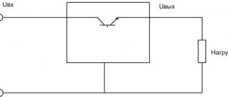
Operating principle
Let's look at how a DIY voltage stabilizer functions.
After connecting the power, capacitance C1 is in a discharge state, transistor VT1 is open, and VT2 is closed. VT3 transistor also remains closed. Through it, current flows to all LEDs and an optitron based on triacs.
Since this transistor is in a closed state, the LEDs do not light up, and each triac is closed, the load is turned off. At this moment, current flows through resistance R1 and arrives at C1. Then the capacitor begins to charge.
The shutter speed range is three seconds. During this period, all transition processes are carried out. After their completion, a Schmitt trigger based on transistors VT1 and VT2 is triggered. After this, the 3rd transistor opens and the load is connected.
The voltage coming from the 3rd winding T1 is equalized by diode VD2 and capacitance C2. Next, the current flows to the divider at resistances R13-14. From resistance R14, a voltage, the magnitude of which directly depends on the magnitude of the voltage, is included in each non-inverting comparator input.
The number of comparators becomes equal to 8. They are all made on DA2 and DA3 microcircuits. At the same time, direct current is supplied to the inverted input of the comparators, supplied using dividers R15-23. Next, the controller comes into action, receiving the input signal of each comparator.
Stabilization of household voltage
The desire to provide stabilized voltage to the household network is an obvious phenomenon. This approach ensures the safety of the equipment in use, often expensive and constantly needed on the farm. And in general, the stabilization factor is the key to increased safety in the operation of electrical networks.
For domestic purposes, a stabilizer is most often purchased for a gas boiler, the automation of which requires connection to a power supply, for a refrigerator, pumping equipment, split systems and similar consumers.
Industrial design of a mains voltage stabilizer, which is easy to purchase on the market. The range of such equipment is huge, but there is always the opportunity to make your own design
This problem can be solved in different ways, the simplest of which is to buy a powerful voltage stabilizer manufactured industrially.
There are a lot of offers of voltage stabilizers on the commercial market. However, purchasing options are often limited by the cost of devices or other factors. Accordingly, an alternative to purchasing is to assemble a voltage stabilizer yourself from available electronic components.
Provided you have the appropriate skills and knowledge of electrical installation, the theory of electrical engineering (electronics), wiring circuits and soldering elements, a homemade voltage stabilizer can be implemented and successfully used in practice. There are such examples.
Stabilization equipment made with your own hands from available and inexpensive radio components may look something like this. The chassis and housing can be selected from old industrial equipment (for example, from an oscilloscope)
What you need to connect
In addition to the stabilizer itself, you will need a number of additional materials:
three-core cable VVGnG-Ls
The cross-section of the wire must be exactly the same as on your input cable, which comes to the main input switch or circuit breaker. Since the entire load of the house will go through it.
three position switch
This switch, unlike simple ones, has three states:
123
You can also use a regular modular circuit breaker, but with this scheme, if you need to disconnect from the stabilizer, you will have to completely de-energize the entire house each time and reconnect the wires.
There is, of course, a bypass or transit mode, but in order to switch to it, you need to follow a strict sequence. This will be discussed in more detail below.
With this switch, you completely cut off the unit with one movement, and the house remains with light directly.
PUGV wire of different colors
You must clearly understand that the voltage stabilizer is installed strictly before the electric meter, and not after it.
Not a single energy supplying organization will allow you to connect in another way, no matter how much you prove that by doing so, in addition to the electrical equipment in the house, you want to protect the meter itself.
The stabilizer has its own idle speed and also consumes energy, even when operating without load (up to 30 W/h and above). And this energy must be taken into account and calculated.
The second important point is that it is highly desirable that in the circuit up to the connection point of the stabilization device there is either an RCD or a differential circuit breaker.
This is recommended by all manufacturers of popular brands Resanta, Sven, Leader, Shtil, etc.
It could be an introductory automatic differential for the whole house, it doesn’t matter. The main thing is that the equipment itself is protected from current leakage
And breakdown of the transformer windings to the housing is not such a rare thing.
Manufacturing stages
To assemble a 220V voltage stabilizer for your home with your own hands, you first need to prepare a printed circuit board measuring 115x90 mm. It is made of foil fiberglass. The layout of the parts can be printed on a laser printer and transferred to the board using an iron.
Let's watch the video, a homemade simple device:
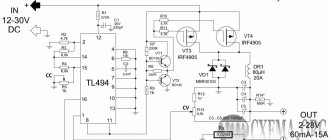
electrical circuit diagram
Next we move on to assembling the transformers. For one such element you will need:
- magnetic core with a cross-sectional area of 1.87 cm²;
- three PEV-2 cables.
The first wire is used to create one winding, and its diameter is 0.064 mm. The number of turns should be 8669.
The two remaining wires will be needed to make other windings. They differ from the first one in diameter being 0.185 mm. The number of turns for these windings will be 522.
If you want to simplify your task, you can use two ready-made TPK-2-2 12V transformers. They are connected in series.
In the case of making these parts yourself, after one of them is ready, they move on to creating the second. It will require a toroidal magnetic circuit. For the winding, choose the same PEV-2 as in the first case, only the number of turns will be 455.
Also in the second transformer you will have to make 7 taps. Moreover, for the first three, a wire with a diameter of 3 mm is used, and for the rest, buses with a cross-section of 18 mm² are used. This will help prevent the transformer from heating up during operation.
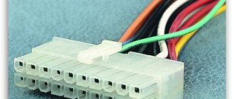
connection of two transformers
It is better to purchase all other components for a device you create yourself in a store. Once everything you need has been purchased, you can begin assembly. It is best to start by installing a microcircuit that acts as a controller on a heat sink, which is made of aluminum platinum with an area of more than 15 cm². Triacs are also mounted on it. Moreover, the heat sink on which they are supposed to be installed must have a cooling surface.
Next you need to install LEDs on the board. Moreover, it is better to choose blinking ones. If it is not possible to arrange them according to the diagram, then you can place them on the side where the printed conductors are located.
If assembling a 220V triac voltage stabilizer with your own hands seems complicated to you, then you can opt for a simpler linear model. It will have similar properties.
The effectiveness of a handmade product
What pushes a person to make this or that device? Most often - its high cost. And in this sense, a voltage stabilizer assembled with your own hands is, of course, superior to a factory model.
In addition, all the parts for such a device were previously purchased in the store, so if they fail, you can always find a similar one.
If we compare the reliability of a stabilizer assembled with our own hands and manufactured at an enterprise, then the advantage is on the side of factory models. At home, it is almost impossible to develop a model with high performance, since there is no special measuring equipment.
Conclusion
There are different types of voltage stabilizers, and some of them are quite possible to make with your own hands. But to do this, you will have to understand the nuances of the operation of the equipment, purchase the necessary components and carry out their proper installation. If you are not confident in your abilities, then the best option is to purchase a factory-made device. Such a stabilizer costs more, but the quality is significantly superior to models assembled independently.