When current passes through an electrical circuit, it is subject to resistance from its individual parts, which in electrical engineering is called resistance. This leads to loss of some power. To correctly calculate the parameters of an electrical circuit, you need to take into account the nature of resistance and know what the effect of its various types is.
What is resistance
Current flowing through wires and various radio components wastes its energy. This phenomenon is quantitatively expressed by the magnitude of the resistance. In electrical engineering, it is divided into active and reactive resistance. In the first case, when a current passes, part of its energy is converted into a thermal form, and sometimes into others (for example, it manifests itself in chemical reactions). The value of active resistance depends on the frequency of alternating electric current and increases with its increase.
The second type of resistance has a more complex nature and occurs when a consumer of electricity is turned on or off in an AC or DC network. In a circuit with reactance, the energy of the electric current is partially converted into another form, and then transferred back, that is, a periodic oscillatory process is observed. Circuit impedance includes active and reactive types, which are taken into account according to special rules.
Inductive reactance
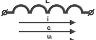
As the current increases, a magnetic field with different characteristics is generated. The most important of these is inductance. The magnetic field, in turn, affects the conductor through which current flows. The effect is opposite to the direction of current change. That is, if the current strength has increased, then the magnetic field will reduce it, and vice versa, if it has decreased, then the field will strengthen it. When the current does not change, the reactance of the inductor will be zero.
Inductive reactance depends on the frequency of the current. The higher it is, the higher the rate of change of this parameter. This means that a stronger magnetic field will be generated. The resulting EMF prevents a change in the electric current.
The calculation of inductive reactance is carried out using the following formula:
XL = L×w = L×2π×f, where the letters indicate:
- L is the inductance of the magnetic field, which is generated by a change in current strength;
- W is the circular frequency of change, which is used in describing the sinusoidal change in current strength;
- Π—pi number;
- f is the current frequency in the usual sense.
With a sinusoidal change in voltage, the current strength will change, falling behind it in phase. Therefore, the reactance of a transformer depends significantly on its inductance.
Which resistance is called reactive and which is active?
Active electrical resistance is an important parameter of the electrical network, which determines the conversion of electrical energy entering a section of an electrical circuit or a separate electrical element into any other type of energy: chemical, mechanical, thermal, electromagnetic. I consider the transformation process irreversible.
Types of the quantity under consideration and formulas for its calculation
Reactance is otherwise called reactance and is the resistance of electrical circuit elements, which is caused by measuring the strength of electric current or voltage due to the existing capacitance or inductance of this element. During reactance, an exchange process occurs between an individual network component and an energy source. This concept is often referred to as simple electrical resistance, but it differs in some respects.
The flow of alternating current does not depend on the type of resistance of the elements and the entire network
Differences between active and reactance
The difference between active and reactance is that when electric current passes through circuit components carrying a resistive load, power losses occur in the form of heat, which cannot be converted back into electrical energy. An illustrative example is an electric stove burner that releases thermal energy. Lighting devices, electric motors, and various cables also have these properties. The phases of the voltage and electric current passing through such components will coincide.
It will be interesting➡ Replacing the mini usb charging plug with micro usb. Micro USB charging wiring diagram. Pinout micro usb 5 pin for charging
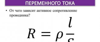
What does the resistance of a conductor depend on?
Reactive loads are distinguished by the presence of capacitive properties or the ability to induct. In the first case, the value of the resistance under consideration depends on the capacitance, in the second - on the electromotive force of self-induction.
Important! A quantity, in contrast to an active one, can have plus and minus signs. It depends on which direction the phase shift is going. When the electric current is ahead of the voltage, there will be a negative indicator, otherwise it will be positive.
What are the differences?
The difference between these types of electrical resistance is that energy does not accumulate “inside” the activity type, since it enters the active element and is given to the environment in the form of another type. This could be heat or mechanical lifting of a load, a glow, a chemical reaction, or giving something speed.
Inductive quantity and its formulas
Important! The energy supplied to an electrical element with active electrical resistance is transformed and converted, but is not returned to the network.
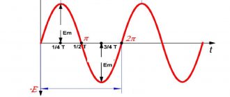
Reactive resistance, on the contrary, accumulates energy within itself for ¼ of the entire period of the sinusoidal electric current, and over the next quarter returns it back to the network. That is, the energy received is not transferred to the environment.
Complex resistance of an individual electrical element of the network R
In the activity type, the phases of electric currents and voltages coincide, therefore, a certain amount of electricity is released. In reactive form, the phases of electric current and voltage diverge, so energy is transferred back. This largely explains why active electrical elements heat up, while reactive elements do not.
Active resistance in an alternating sinusoidal current circuit
Areas of manifestation
The reactance of electrical resistance manifests itself in capacitance and induction. The first is determined by the presence of capacitance in the conductors and windings or the inclusion of various capacitors in the AC electrical circuit. The higher the capacitance of the consumer and the angular frequency of the electric current signal, the lower the capacitive characteristic.
You may be interested in this Features of active-capacitive load
The resistance that a conductor provides to alternating current and the electromotive force of self-induction is called inductive. It depends on the inductance of the consumer. The higher its inductance and the higher the frequency of alternating electric current, the higher the inductive electrical resistance. It is expressed by the formula: xl = ωL, where xl is the electrical induction resistance, L is the inductance, and ω is the angular frequency of the current.
Capacitive reactance electrical resistance manifests itself, for example, in a capacitor, which accumulates electricity in the form of an electromagnetic field between its plates. Inductive electrical reactance can be observed in an inductor, which stores energy in the form of a magnetic field inside its winding.
Any resistor, power lines, windings of a transformer or electric motor can have active electrical resistance.
EMF induction can be observed in the throttle
Thus, active resist and reactance differ in many ways from each other, not only by the difference in name, but also in physical properties. The first type converts electricity into another form and releases it into the environment. The second one returns it back to the power grid.
Alternating current
In order to understand what active resistance is, it is necessary to understand the phenomenon of alternating current itself. An alternating current is a type of current that continuously changes the direction of its flow. During flow, the alternating current potentials are constantly changing. This occurs due to the operation of the generator, or more precisely due to the interaction of the magnetic field with the copper winding. The movement can be clearly seen using an oscilloscope. Its shape resembles a sinusoid.
It will be interesting➡ Methods of connecting an asynchronous electric motor
The role of alternating current is difficult to overestimate. Its main advantage is the ease of transmission from source to consumer, the ability to lower or increase the voltage using transformers. Also, alternating electric currents can be delivered to the consumer at much lower cost.
Active resistance
Alternating current is delivered to the consumer for the purpose of converting it into other types of energy, for example, heat and light. In household networks, the use of single-phase alternating current predominates. When connecting a consumer, active resistance is created.
A simple AC circuit with active resistance includes a current generator and an ideal resistor. In this case, the necessary conditions for an ideal circuit must be met:
- Active resistance should not be equal to zero, a prerequisite.
- The capacitance and inductance of the circuit must be zero.
Also, for ideal active resistance the following conditions must be met:
- Ohm's law is observed for the instantaneous, rms and amplitude parameters of the circuit.
- The value is completely independent of amplitude fluctuations.
- There is no phase shift between current and voltage.
- An element under voltage releases a share of thermal energy, that is, it heats up.
All these conditions allow electrical devices to operate within precisely defined parameters with maximum efficiency. Any change may be caused by a lack of a reliable contact connection or a malfunction of the consumer itself.
In order to calculate the value of active resistance in a circuit, it is necessary to know the value of voltage and current. The formula used for calculation is: R=U/I. The formula consists of the following values:
- “R” - resistance, Ohm;
- “U” - voltage value, volts;
- “I” is the current value, ampere.
Then you can do a simple calculation. The consumer is an electric oven connected to a single-phase alternating current circuit:
- Circuit voltage is 240 volts.
- When measuring the current, a value of 4 amperes was obtained.
- R= 240/4=60 Ohm.
The calculated resistance value is not the final value. It is influenced primarily by the cross-section of the wires included in the circuit and the interaction pattern between the circuits of capacitive and semiconductor elements.
The active value of the circuit also causes a permanent loss of the original electrical energy, and also leads to a decrease in power.
Impedance
When using several varieties, it is important to know how they fit together. Active resistance is present in any circuit. It helps convert part of the electrical energy into heat. Reactance occurs only in an alternating current circuit. To determine its value, it is necessary to subtract capacitive from inductive. This characteristic shows the energy that pulsates in a circuit, moving from one form to another.
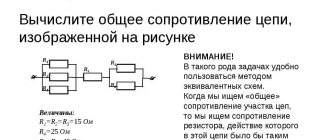
Impedance is the sum of active and reactance in an AC circuit, but this addition must be done in a special way. To do this, you need to draw a right triangle, the legs of which should have a length equal to the value of active and reactive resistance, respectively.
The length of the hypotenuse will numerically express the total resistance of the electrical circuit. To determine it, a rule is used that says that the sum of the squares of the legs is equal to the square of the hypotenuse. This rule is called the Pythagorean theorem. Therefore, the formula that can be used to find the total resistance is:
Z = √(R^2+〖(XL-XC)〗^2 ), where
- Z—impedance;
- R is the value of the active component;
- XL and XC are the values of the inductive and capacitive parameters, respectively.
Therefore, when calculating impedance or impedance, you need to consider what capacitance and inductance are and how they may appear in electrical circuits. These quantities are also called parasitic, since they can negatively affect the operation of the electrical appliance. Their occurrence is attributed to unpredictable factors. In this case, capacitive or inductive reactance, which has a small value, can be neglected when performing calculations.
Addiction
The amount of active resistance largely depends on the diameter of the conductors. When high-frequency currents are applied, the resistance of the conductor can be reduced only if its surface layer is much thinner than the main one. In order to achieve an ideal cross-section, this layer must consist of a material with very high conductivity, such as gold or silver. This effect occurs due to the interaction of voltage and the magnetic field formed by it. The field strongly influences the current flowing through the conductor and pushes it to the surface layer. Thus, closer to the surface of the conductor, the conductivity decreases and becomes critically small in its upper layer.
The following effects are also present: leakage losses and dielectric losses. Both effects are associated with the presence of a capacitor in the circuit. Dielectric losses occur due to an increase in the temperature of the dielectric inside the capacitor. Leakage loss occurs due to the breakdown fraction of the capacitor insulator.
Hysteresis. This is also a type of AC energy loss. This loss occurs when a magnetic field forms around metal objects. Electromagnetic influence leads to heating of the metal, which means energy conversion.
The last leakage factor is radio emission. Radio waves appear due to a strong magnetic field and its interaction with the metals of the circuit. For suppression, especially in radio equipment, screens are used that absorb part of the field and repel the rest.
Instantaneous power in an alternating current circuit with active resistance.
With variable voltage and current values, the rate of conversion of electrical energy in the receiver, i.e. its power, also changes. Instantaneous power is equal to the product of instantaneous voltage and current values: p = Umsinωt * Imsinωt = UmImsin2ωt
From trigonometry we find
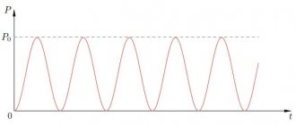
A more clear idea of the nature of the change in power in a circuit is given by a graph in a rectangular coordinate system, which is constructed after multiplying the ordinates of the voltage and current curves corresponding to a number of values of their common argument - time t. The dependence of power on time is a periodic curve (Fig. 13.2). If the time axis t is raised according to the drawing by the amount p = Pm√2 = UmIm√2, then relative to the new axis t' the power graph is a sinusoid with double frequency and an initial phase of 90°:
Thus, in the original coordinate system, the instantaneous power is equal to the sum of the constant value P = UmIm√2 and the variable p':
p = P + p'
Analyzing the instantaneous power graph, it is easy to notice that the power remains positive during the period, although the current and voltage change their sign. This is achieved due to the phase coincidence of voltage and current.
It will be interesting➡ Network voltage
The constancy of the power sign indicates that the direction of the flow of electrical energy remains unchanged during the period, in this case from the network (from the energy source) to the receiver with resistance R, where the electrical energy is irreversibly converted into another type of energy. In this case, electrical energy is called active.
If R is the resistance of the conductor, then, in accordance with the Lenz-Joule law, electrical energy in it is converted into heat.
How to calculate capacitive reactance
Let's look at an example of calculating capacitive reactance: suppose a 6 µF capacitor is connected to an AC outlet with a voltage of 40 V and a frequency F of 60 Hz.
To define capacitive reactance, the definition given at the beginning is used. Angular frequency ω is defined as:
ω = 2πf = 2π x 60 Hz = 377 s-1
It will be interesting➡ Twisted pair: categories, crimping, work tips
This result is then plugged into the definition:
XC = 1 / ωC = 1 / (377 s-1x 6 x10 -6 F) = 442.1 Ohm
Now let's look at the amplitude of the current circulating in the circuit. Since the source offers a voltage amplitude VC = 40 V, we use the relationship between capacitive reactance, current and voltage to calculate the current amplitude or maximum current:
iC = VC / ICSC = 40 V / 442.1 Ohm = 0.09047 A = 90.5 mA.
If the frequency becomes very high, the capacitive reactance becomes small, but if the frequency becomes 0 and we have direct current, the reactance goes to infinity.
Active power for an AC circuit with active resistance
The rate of conversion of electrical energy into another type of energy over a finite period of time, much longer than the period of current change, is characterized by average power. It is equal to the average power over the period, which is called active.
Active power is the arithmetic average of instantaneous power over a period.
For the circuit under consideration, the active power P can be easily determined from the graph in Fig. 13.2. The average power value is equal to the height of a rectangle with a base T, equal to the area bounded by the curve p(t) and the abscissa axis (shaded in the figure).
The equality of areas PT = Sp is satisfied if the height of the rectangle is taken equal to half the greatest instantaneous power Pm.
In this case, the part of the area Sp located above the rectangle fits exactly into the remaining unshaded part of it:
P=UI
The active power for a given circuit is equal to the product of the effective values of current and voltage:
P = UI = I2R
From a mathematical point of view, active power is the constant component in the instantaneous power equation p(t) [see expression (13.2)].
The average power over a period can be found by integrating equation (13.2) within the period:
Resistance R, determined from formula (13.3) by the ratio of the active power of the circuit to the square of the effective current, is called active electrical resistance.
Related topics:
[ads-pc-1]
Current and voltage.
When active resistance R is connected to an alternating current circuit (Fig. 175, a), the source voltage creates a current i in the circuit. If the voltage changes sinusoidally u = Uтsin ?t, then the current i also changes sinusoidally:
i = It sin ?t
Wherein
It= Uт/ R
Thus, current and voltage change according to the same law; they simultaneously reach their maximum values and simultaneously pass through zero (Fig.
175, b). Consequently, when an active resistance is connected to an alternating current circuit, the current and voltage are in phase (Fig. 175, c).
If both sides of the equality It = Ut/ R are divided by ?2, then we obtain the expression for Ohm’s law for the circuit under consideration for the effective values of voltage and current:
I=U/R
Consequently, for an alternating current circuit containing only active resistance, this law has the same mathematical form as for a direct current circuit.
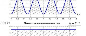
Electrical power. Electrical power p in a circuit with active resistance at any time is equal to the product of the instantaneous values of current i and voltage i. Consequently, instantaneous power p is not a constant value, as with direct current, but varies along a curve (see.
rice. 175, b). This curve can also be obtained graphically by multiplying the ordinates of the current i and voltage curves and at different angles ?t.
The power change occurs with double frequency ?t in relation to the change in current and voltage, i.e. one period of power change corresponds to half the period of change in current and voltage.
All power values are positive. Physically, a positive power value means that energy is transferred from the source of electrical energy to the receiver. Maximum power value at ?t = 90° and ?t = 270°
Pmax= UtIt= 2UI
Rice. 175. Scheme of connecting active resistance to an alternating current circuit (a), curves of current i, voltage and, power p (b) and vector diagram (c)
In practice, the energy W created by an electric current is judged not by the maximum power, but by the average power Рср = Р, since this energy can be expressed as the product of the average power value Р by the time the current flows:
W = Pt.
The instantaneous power curve is symmetrical relative to the AB line, which corresponds to the average power value P. Therefore
P = Pmax/ 2 = UI
Using formula (67) of Ohm's law, active power can also be expressed as P = I2R or P=U2/R.
In electrical engineering, the average power consumed by an active resistance is usually called active power, or simply power, and is denoted by the letter P.
Surface effect. It should be noted that the active resistance of conductors in an alternating current circuit is always greater than their resistance in a direct current circuit.
Alternating current i does not flow uniformly over the entire cross-section of the conductor, like direct current i, but is displaced onto its surface (Fig. 176, a). Therefore, the useful cross-section of the conductor seems to decrease and its resistance increases with alternating current.
This phenomenon is called the surface effect. The uneven distribution of alternating current over the cross section of the conductor is explained by the action of e. d.
With. self-induction induced in a conductor by a magnetic field, which is created by current I passing through the conductor. This magnetic field acts not only in the space surrounding the conductor (external flux F2), but also inside the conductor itself (internal flux F2) (Fig.
176, b). Therefore, layers of a conductor located closer to its center will be covered by a greater magnetic flux than layers located closer to its surface, and e.g. d.
With. The self-induction induced in the inner layers will be greater than in the outer ones. Since e.
d.s. self-induction prevents change
Rice. 176. Scheme of the flow of direct I and alternating i currents through a conductor (a) and the occurrence of a surface effect (b)
Rice. 177. Scheme of heat treatment of parts with high-frequency currents: 1 - high-frequency inductor; 2 - part to be hardened; 3 - heated layer
current, the latter will strive to pass where e. d.
With. self-induction has the smallest value, i.e.
will pass predominantly through the surface layers of the conductor. As a result, the current density V in the surface layers will be greater than in the internal ones. The higher the frequency of the current, the greater the e.
d.s. self-induction is induced in the inner layers of the conductor and the more the current is displaced to the surface.
At a frequency of 50 Hz, the increase in the resistance of copper and aluminum conductors with their small diameter is practically negligible, and the resistance of such conductors in AC and DC circuits can be considered the same. But for copper and aluminum conductors with a diameter of over 10 mm, and for steel conductors with even smaller diameters, it is necessary to take into account the influence of the surface effect on their active resistance when calculating.
With high-frequency currents used in radio engineering, television and various high-frequency installations, in order to better utilize the metal of the conductors, they are usually made hollow.
Various methods of high-frequency hardening and heat treatment are based on the property of high-frequency alternating current to flow mainly along the surface of conductors.
For example, during high-frequency heat treatment of parts with eddy currents (Fig. 177), these currents are induced mainly in the surface layer of the metal. They quickly heat up the surface layers of the workpiece, before its inner part has time to noticeably heat up due to the thermal conductivity of the metal.
[ads-pc-2]
In an AC electrical circuit, there are two types of resistance: active and reactive. This is a significant difference from DC circuits.
How is reactance measured?
In itself, the phenomenon of reactance is characteristic only of circuits with alternating current. It is designated by the Latin letter “X” and measured in Ohms. Unlike the activity variant, reactance can have both positive and negative meanings. The “+” or “-” sign corresponds to the sign by which the phase of the electric current and voltage shifts. The sign is positive when the current lags behind the voltage and negative when the cat leads the voltage.
Important! Absolutely pure electrical reactance has a phase shift of ± 180/2. That is, the phase “moves” by π/2.
Capacitance
It has a different nature than inductive. It is convenient to illustrate this concept using the example of an electrical circuit consisting of a power source, the terminals of which are connected to the plates of a capacitor. Immediately after connection, a charge will gradually accumulate on them, creating a current in the circuit.
After reaching the limit value, which is determined by the capacitance of the part, the current will not flow through the circuit. If you then disconnect the wires from the terminals and then connect the latter, then charges will begin to move between them until the potential difference becomes zero.
If you connect an AC source to the capacitor, the following will happen. As the potential difference increases, the charge on the capacitor plates will increase. When the voltage enters the decreasing phase, the accumulated charge will begin to drain from them, forming a current in the opposite direction. Then the potential difference will become negative, but in absolute value it will increase to its maximum value. In this case, the capacitor will begin to charge again, but the sign of the incoming charges will not be the same as it was before.
When the voltage begins to increase (decreasing in absolute value), the charge will drain from the capacitor plates. When the potential difference at the source reaches zero and continues to increase, a new cycle of changes will begin.
At each stage of the described situation, the current from the capacitor plates will have the opposite direction to that generated by the variable potential difference of the power source.
The decrease in current that occurs in this way represents the physical meaning of capacitance. It is denoted by the letters XC and is calculated using the formula:
XС = 1/(w×C) = 1/(2π×f×C), where
- C is the capacitance of the capacitor used;
- w is the circular frequency of alternating current;
- π—pi number;
- f is the frequency of alternating current.
In the case under consideration, changes in current lag behind voltage.
How to measure resistance correctly
When working with radio equipment, sometimes it is necessary to measure not only the activity, but also the electrical reactance (inductance and capacitance). For measurements, the indirect method of using a multimeter is used, and more accurate values are obtained using the bridge method.
The indirect method is the simplest to implement, since it does not require additional switching circuits. One requires three separate instruments: an ammeter, a voltmeter and a wattmeter. If you measure the voltage and current in the circuit, you can get the total electrical resistance: Z=U*I After measuring the active power P, you can get the value of the active resistance of an individual element: R= P/I².
Capacitive reactance applications
High-pass filters, low-pass filters, bridge circuits for measuring capacitance and inductance, and phase shift circuits are some of the major applications of circuits that contain capacitive reactances combined with inductances and electrical resistances.
In stereo systems, some speakers come with separate speakers. a woofer (larger) for low frequencies and a tweeter or small horn for high frequencies. This improves performance and sound quality.
They use capacitors to prevent low frequencies from entering the tweeter, and an inductor is added to the woofer to avoid high frequency signals because inductance has a reactance proportional to frequency: XL = 2πfL.
Coil
An inductor is a metal or ferrite core around which several turns of copper wire are wound. The element has the following properties:
- Due to inductance, the rate of change of currents is limited.
- As the frequency of the current increases, the coil is able to increase its resistance (skin effect).
- Creates a magnetic field.
- Increases and accumulates tension.
- Creates a phase shift in alternating current.
- Proportional to the speed of current movement, it creates a self-inductive emf.
All these properties are used in the development of radio receivers, frequency generators, testers, magnetometers and other types of complex equipment.
Principle of operation
An inductor only works when electric current passes through a set of turns of winding. When an element is connected to an electrical circuit, current begins to flow through the coil. Due to the interaction of the wire with the metal core, a magnetic flux is created. The flux is completely proportional to the inductance of the coil and the magnitude of the current. The magnitude of the magnetic flux can be calculated using the following formula: Ф=L×I.
The elements of the formula are:
- “F” is the magnitude of the magnetic flux.
- "L" - induction.
- “I” is the current value.
The number of turns affects the magnitude of the self-induction emf. The turns interact not only with the core, but also with each other, which leads to an increase in EMF.
In an alternating voltage circuit, the magnitude of the EMF can provoke a phase difference between voltage and current up to 90 degrees.
Design and varieties
All types of inductors have the same design, regardless of their application. The features introduced to obtain individual parameters affect the type of part.
- Solenoid. Component with increased overall length of winding wire. The winding is larger than the diameter of the part.
- Toroidal. In such a coil, the solenoid is made in the shape of a “torus”.
- Multilayer type, has several rows of winding.
- Sectioned. The winding has several divided sections, sometimes made of wire of different sections. The best known coil of this type is the transformer or choke.
- Universal, can combine several winding options at once.
Regardless of design, all coils operate on the same principle.
Inductance
The inductance of a coil is its ability to store electricity. This setting depends on:
- Number of turns.
- Wire cross-sections and lengths.
- Design features of the part.
- From the material, length, diameter and shape of the core.
- From the distance between turns.
- Availability of a screen.
In radio electronics it is not customary to indicate the value of inductance. Manufacturers mark parts with the number of turns and indicate the type of core.
Resistance measurement and calculation formula
The active resistance of the inductor can only be measured in a de-energized state. This is done using a multimeter.
- The multimeter must be switched to ohmmeter mode.
- Connect the red measuring probe to the first output of the coil.
- Connect the black test lead to the second output.
- The device will only show the active resistance of the winding.
Using a tester, you can only determine the integrity of the turns. If the element is connected to a live circuit, then the resistance value is found by a simple calculation using the formula: Z=U/I.
It will be interesting➡ Resonance of tension. Where is the phenomenon of voltage resonance used?
To calculate using this formula, using a tester, first determine the value of current (I) and voltage (U). Active resistance is measured in Ohms.
Knowing the formula for calculating active and inductive resistance, the total resistance of the element can be found using the formula:
Z=2×(R×R+XL×XL)
In this expression, R is resistance and XL is inductive.
Capacitive conductivity of lines
Electric lines, in addition to active and inductive resistance, are also characterized by capacitive conductivity, which is due to the capacitance between the wires and between the wires and the ground.
The value of the working capacitance in a three-phase overhead line can be approximately determined by the formula:
From this formula it is clear that the working capacity will increase with an increase in the cross-section of the wires and a decrease in the distance between them. Therefore, with equal cross-sections of current-carrying parts, low-voltage lines have a greater working capacity than high-voltage lines. Due to the small distances between the current-carrying conductors of the cable and the greater dielectric constant of the insulation compared to air, the working capacity of the cable line is significantly greater than the capacity of the overhead line.
The capacitive conductivity of a single-circuit overhead line is determined by the formula:
Determining the working capacitance of a cable line using formulas that include the dielectric constant of the cable insulation, geometric dimensions and other design features is not an easy task, therefore the values of the working capacitance are determined using special tables compiled by the manufacturer for various brands of cables, depending on their nominal voltage.
The capacitive current at the beginning of the line at idle (with electrical receivers turned off) can be determined from the formula:
Where: U – line voltage of the network, V; l – line length, km;
Capacitive currents are of serious importance in overhead lines with operating voltages of 110 kV and above and in cable lines with voltages above 10 kV. When calculating electrical networks with voltages lower than those listed above, the line capacitance may not be taken into account. The capacitance of the conductive parts of the line in relation to the ground is important when calculating grounding devices and protection.
In a network with an isolated neutral, the magnitude of the capacitive current of a single-phase ground fault can be approximately determined by the formulas:
- For overhead line:
- For cable line:
Coil resistance
Active resistance is determined by the ohmic characteristics of the winding wires. When operating at low frequencies, the ohmic resistance does not depend on frequency. In powerful devices, it is necessary to take into account the proximity effect, which consists in the fact that currents and the magnetic field they generate cause displacement of the current in the wires of adjacent turns. As a result, the effective usable cross-section of the wire decreases and its ohmic resistance increases.
Note! At high frequencies, the skin effect appears, which consists in the fact that the current is displaced into the surface layers of the wire. As a result, the usable cable cross-section is reduced. To reduce the skin effect, instead of one conductor, a bundle of several thinner ones is used - Litz wire, or the surface of the wire is coated with a layer of silver, since it has the lowest resistivity.
Skin effect
In powerful electromagnetic systems (particle accelerators), to reduce active resistance, the property of superconductivity is used - the complete disappearance of resistance when some materials are cooled below a critical temperature.
Litz wire
In many cases where inductors are used, the effect of winding resistance must be taken into account. This parameter can have a negative effect not only by reducing the quality factor, but also cause increased heating of the winding conductors when the device operates with high currents.
Determination of active resistance of wires
It is easiest to determine the active resistance of wires using reference data compiled on the basis of GOST 839-80 - “Bare wires for overhead power lines”, tables 1 - 4. You can find these tables directly in GOST itself, I will give just a few. It is not recommended to use all known formulas for determining active resistance [L1. p.18], this is due to the fact that the actual cross-section differs from the nominal cross-section, the wires were produced at different times, according to different GOSTs and specifications, and the values of conductivity (ρ) and resistivity (γ) are different:
Where:
- γ – the value of specific conductivity for copper and aluminum wires at a temperature of 20 °C is accepted: for copper wires – 53 m/Ohm*mm2; for aluminum wires – 31.7 m/Ohm*mm2;
- s – nominal wire (cable) cross-section, mm2;
- l – line length, m;
- ρ – the resistivity value is accepted: for copper wires - 0.017-0.018 Ohm*mm2/m; for aluminum wires – 0.026 - 0.028 Ohm*mm2/m, see table 1.14 [L2. p.30].
The active resistance of steel wires cannot be calculated mathematically. Therefore, I recommend using appendices P23 - P25 [L1.] to determine active resistance. p.80,81].
Capacitance
Let us assume that a capacitor of capacitance $C$ is included in a section of the circuit, and $R=0$ and $L=0$. We will consider the current strength ($I$) to be positive if it has the direction indicated in Fig. 2. Let the charge on the capacitor be equal to $q$.
We can use the following relationships:
Try asking your teachers for help
If $I(t)$ is defined by equation (1), then the charge is expressed as:
where $q_0$ is an arbitrary constant charge of the capacitor, which is not associated with current fluctuations, so we can assume that $q_0=0.$ We obtain the voltage equal to:
Formula (6) shows that the voltage fluctuations on the capacitor lag behind the current fluctuations in phase by $frac<2>.$ The voltage amplitude across the capacitor is equal to:
The quantity $X_C=frac<1>$ is called reactance capacitance (capacitance, apparent resistance of the capacitance). If the current is constant, then $X_C=infty $. This means that no direct current flows through the capacitor. From the definition of capacitance it is clear that at high oscillation frequencies, small capacitances are small resistances to alternating current.