What is power in electricity: simply about the complex
I remembered the epic about Ilya Muromets, when he applied all his power to the nightingale robber. The poor guy immediately started to see sparks coming out of his eyes, like the flames from the top picture on the incorrectly installed wiring.
In simple words: power in electricity is a power characteristic of energy, which is used to evaluate both the ability of generator sets to produce it and the capabilities of consumers and transport routes.
All these areas must be accurately assembled and adjusted to ensure safe operation. As soon as a malfunction occurs anywhere, an accident immediately develops in the entire circuit.
When it comes to home electrical equipment, you have to constantly strike a balance between:
- devices connected to the network;
- design of wires and cables;
- setting up protective devices.
Only a comprehensive solution to these three issues can ensure the safety of wiring and residents.
How to calculate electrical power at home
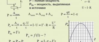
Formulas for calculating power in electricity allow you to perform a qualitative assessment of the safety of each of the above items.
They are not difficult to use. In previous articles I have already provided an electrician’s cheat sheet, where they are presented in a visual form for DC circuits.
They are completely valid for the active component of alternating current power that does useful work. By the way, besides it there is also a useless one - reactive, associated with energy loss. The second section is devoted to its description.
It is convenient to do such calculations using an online calculator. It eliminates routine mathematical calculations and arithmetic errors.
With any of the methods, to calculate active power, you need to know two of three electrical quantities:
- current strength I;
- applied voltage U;
- circuit section resistance R.
How to measure electrical power at home
There is another possibility for estimating active power: its measurement in an operating circuit using special devices: wattmeters.
An industrial laboratory wattmeter can provide accurate measurements. It is manufactured both as a device operating on analog signals and using digital technologies.
In household wiring, precise calculations are not needed. Various types of simpler wattmeters are produced for it.
Devices that can be plugged into an outlet and connected to a power cord from the consumer are popular, turn them on and immediately take readings on the display in watts.
They are called that: wattmeter socket. They measure pure active AC power.
Such devices relieve the electrician from performing complex operations under voltage when it is necessary to measure:
- effective voltage;
- current strength;
- phase shift angle between current and voltage vectors.
Then all the data additionally needs to be entered into the formula for calculating power by current and voltage, and calculations must be made using it.
This method can be simplified by carefully observing the electrical meter of a rotating disk induction system. It calculates the work done: the power consumed over a certain time.
However, the rotation speed of the disk precisely characterizes the amount of consumption. You just need to count how many times it turns around in a minute and convert it to watts according to the plate located on the case.
Current strength in the circuit when resistors are connected in series
Let's make sure that the current strength when connecting resistors in series is the same everywhere. I wrote here how to measure constant voltage current. As you can see, the multimeter showed a value of 0.04 A or 40 mA at the beginning of the circuit, in the middle of the circuit and even at the end of the circuit. Wherever we break our circuit, the current value is the same everywhere.
Why Circuit Reactance Affects AC Power
A sinusoidal voltage harmonic, entering a resistive resistance, changes the magnitude of the current without its deviation on the complex plane.
Such current performs useful work with minimal energy losses, generating active power. The frequency of the signal does not have any effect on it.
The resistance of the capacitor and inductance depends on the frequency of the harmonic. Its opposition deflects the direction of the current on each of these elements in different directions.
Such processes are associated with the loss of part of the energy for useless transformations. They consume power Q, which is called reactive. Its influence on the total power S and the connection with active P is conveniently represented graphically by a right triangle.
I wanted to draw it against the background of equipment made from piles of porcelain and metal, where I had to work for quite a long time. I got distracted. Don't judge harshly for this.
Compare it with the resistance triangle I published earlier. Do you find any common features?
They are the geometric proportions of the figure, the formulas describing them and the angle φ, which determines the total power loss. Let me move on to a more detailed consideration of them.
Calculation of voltage, current and resistance
Ohm's law is designed to find the unknown third if the first and second are known. From this point on, in order to simplify Ohm's law, we will use Ohm's triangle. This is the triangle:
Let's figure out the voltage, to find the voltage using the Ohm triangle, you need to cover the voltage with your hand - U , only I - current and R - resistance remain, the front is a vertical bar, the vertical bar is from bottom to top, this vertical line means multiplication, which means that To find the voltage, you need to multiply the current by the resistance.
Here is the formula: U=I*R , where U is voltage, I is current, R is resistance.
Now let's try to find the current, cover I , now in front of the voltage and resistance there is a horizontal line, horizontal is the line that goes from left to right. A horizontal line means division. This means that to find the current, you need to divide the voltage by the resistance.
The formula is as follows: I = U\R , where I is current, U is voltage, R is resistance.
Let's find the resistance, close R , then we will again get a horizontal line in front of the voltage and current, which means we need to divide.
The formula for calculating resistance is: R=U\I , where R is resistance, U is voltage, I is current. So, we learned how to use Ohm's triangle and learned about Ohm's Law. Now, perhaps, let's learn from examples.
Formulas for calculating power for single-phase and three-phase power circuits
In the ideal theoretical case, a three-phase circuit consists of three identical single-phase circuits. In practice there are always some deviations. But, in most cases, they are neglected in analyzes.
Therefore, we consider the simplest question first.
Graphs and formulas for single-phase voltage
How does a resistor work?
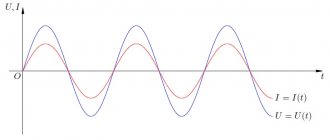
On a purely resistive resistance, the sinusoids of current and voltage coincide in angle and are directed equally at each half-cycle. Therefore, their product, which expresses power, is always positive.
Its value at an arbitrary moment of time t is called instantaneous, denoted by the lowercase letter p.
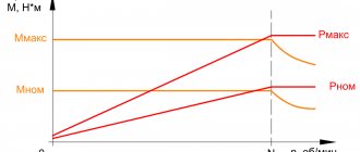
The average power value over one period is called the active component. Its graph for alternating current has the shape of a symmetrical burst with a maximum value of Pm in the middle of each half-cycle T/2.
If we take half of its value Pm/2 and draw a straight line during one period T, we will get a rectangle with ordinate P.
Its area is equal to two areas of the graphs of the active components of any one half-cycle. If you look at the picture more closely, you can imagine that the top part of the splash has been cut off, turned upside down and filled the free space below.
Presentation of this graph helps to remember that the power of direct and alternating current at active resistance is calculated using the same formula and does not change its sign.
The graph of instantaneous values of active power of alternating current on a resistive resistance has the form of repeating positive waves. But in one period it does the same work as in direct current and voltage circuits.
There is no reactive loss created across the resistor.
How inductance works
The coil with the winding stores the energy of the magnetic field with its turns. Thanks to the process of its accumulation, the inductive reactance moves the current vector forward by 90 degrees relative to the applied voltage on the complex plane.
By multiplying their instantaneous values, we obtain the power values, which during one period changes signs (direction) in each half-cycle.
The frequency of power changes across the inductance is twice as high as that of its components: current and voltage sinusoids. It consists of two parts:
- active, designated by the index PL;
- reactive QL.
The reactive part on the inductance is created due to the constant exchange of energy between the coil and the applied source. Its value is influenced by the value of inductive reactance XL.
How does a capacitor work?
The capacitor constantly accumulates charge between its plates. Due to this, the current vector shifts forward by 90 degrees relative to the applied voltage.
The instantaneous power graph resembles the previous one, but starts with a negative half-wave.
The reactive component released on the capacitor depends on the value of capacitance XC.
How a real circuit works with all types of resistance
In their pure form, the above graphs and expressions are not found so often. In fact, the transmission of electricity and its operation on alternating current are associated with the complex overcoming of the forces of electrical resistance of resistors, capacitors and inductances.
Moreover, some of these components will prevail. For such cases, the conversion of electrical energy into instantaneous power can be one of the following types.
The top picture shows the case when the current vector lags behind the applied voltage, and the bottom picture leads.
In both cases, the value of the active component decreases from the total value by a value expressed as cosφ. Therefore, it is commonly called power factor.
Cosine phi (cosφ) is used in analyzing the triangle of power and resistance and characterizes energy losses.
How does a three-phase power supply circuit work?
The input switchboard of a multi-storey building receives three-phase voltage from the power supply organization, generated by industrial generators.
If desired, the owner of a private house can connect it, for a fee, which is what many do. In this case, the working diagram and voltage diagram looks like this.
In the old TN-C grounding system it is made with a four-wire connection, and in the new TN-S it is made with a five-wire connection with the addition of a protective PE conductor. I do not show it in this diagram for simplicity.
During operation, each phase must be loaded with equally equal currents. Then the most favorable optimal mode will be created in the home wiring without dangerous energy imbalances.
In this case, the formula for calculating power by current and voltage for a three-phase circuit can be represented by a simple sum of similar formulas for the components of single-phase circuits.
And since they are all identical, they are simply tripled.
For example, when the active power of phase B has the expression Рв=Uв×Iв×cosφ, then for the entire three-phase circuit it will be expressed by the following formula:
P = Pa+Pv+Pc
If we mark the phase expression with the letter f. for example Pf, you can write:
P = 3Pph = 3Uph×Iph×cosφ
The reactive component will be calculated similarly
Q = Qa+Qв+Qc
Or
Q = 3Qph = 3Uph×Iph×sinφ
Since P and Q represent the dimensions of the legs of a right triangle, the hypotenuse or total component can be calculated as the square root of the sum of their squares.
S = √(P2+Q2)
How three-phase apparent power is taken into account
In the power system, and even in a private home, it is necessary to analyze the connected loads and distribute them evenly among the voltage sources.
Numerous designs of measuring instruments work for this purpose. On the control panels of substations there are panel wattmeters and varmeters designed to operate at different ratios.
Old analog instruments are shown in this picture.
In order to avoid confusion in the calculation records, different names of units have been introduced. They are designated:
- VA - (Russian), VA (international) voltampere for the full amount of power;
- W - (Russian), var (international) watt - active;
- var (Russian), var (international) - reactive.
Analog instruments measure only the active or reactive component, and the full value must be calculated using formulas.
Many modern digital devices are capable of performing this function automatically.
Pavel Victor's video tutorial complements my material. I recommend watching it.
How a voltage divider works in practice
So we have these two resistors and our favorite multimeter:
We measure the resistance of a small resistor, R1 = 109.7 Ohms.
We measure the resistance of the large resistor R2 = 52.8 Ohms.
We set the power supply to exactly 10 Volts. We measure voltage using a multimeter.
We cling to these two resistors, soldered in series, with the power supply. Let me remind you that there is exactly 10 volts on the block. The ammeter reading on the power supply is also a little inaccurate. We will also measure the current strength using a multimeter in the future.
We measure the voltage drop across a large resistor, which has a nominal value of 52.8 ohms. The multimeter measured 3.21 Volts.
We measure the voltage across a small resistor with a nominal value of 109.7 Ohms. The voltage drops across it is 6.77 Volts.
Well, with mathematics, I think everyone is fine. We add these two voltage values. 3.21+6.77 = 9.98 Volts. Where did the other 0.02 Volt go? We'll chalk it up to the error of the probes and measuring instruments. Here is a clear example that we were able to separate the voltage into two different voltages. We have once again verified that the sum of the voltage drops across each resistor is equal to the supply voltage that is supplied to this circuit.
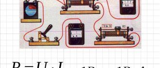
Electrical measurements.
Let's draw a simple electrical circuit consisting of a battery “B” and a load “R”, and consider how it is necessary to measure the current flowing through the circuit and the voltage across the load.
To measure the current flowing in the circuit, it is necessary to connect a measuring device (ammeter) to the gap between the power source and the load.
In order to have as little influence on the measured circuit as possible and to increase the measurement accuracy, ammeters are made with a very low internal resistance, that is, if you include an ammeter in the open circuit of the circuit being tested, it will practically not add additional resistance to the measured circuit, and the flowing along the circuit, the current will practically not change, or will decrease by a very small amount, which will not have a significant effect on the final measurement result.
Therefore, it is strictly forbidden to measure the “current flowing to the load” by connecting an ammeter in parallel with the load, or directly at the power source (without load) and thus try to measure the output current supplied by the power source or lighting network.
This is equivalent to connecting a regular wire in parallel with the load or power source. To put it simply, short-circuit the circuit. If the power source has good power, there will be a very strong B A X . The consequences can be very different, from failure of the measuring device (ammeter), which usually happens, to knocked out plugs (gas stations) in the apartment and loss of power to the room and possible electric shock.
To measure the voltage across a load, it is necessary that the voltmeter connected to it does not shunt the load and does not have a noticeable effect on the measurement result. To do this, voltmeters are made with a very high input resistance and, on the contrary, they are connected in parallel to the circuit being measured. Due to the high input resistance of the voltmeter, the resistance of the measured circuit practically does not change, or changes very little, without having a noticeable effect on the measurement result.
The figure above shows the procedure for connecting an ammeter and a voltmeter to measure the voltage across the load and the current flowing through it. The polarity of connecting measuring instruments to the measured circuit is also indicated.
Voltage squared divide
KPK teacher website: Information technology, Computer graphics, Physics
Voltage is measured with a voltmeter (V), and current through the load (R) is measured with an ammeter (A).
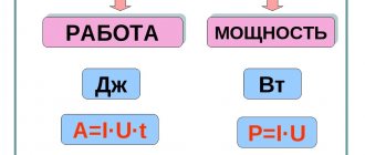
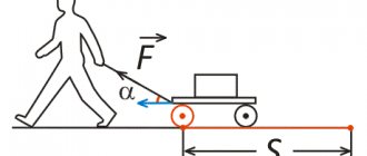
The faster the work is done, the greater the power of the performer.
A powerful car accelerates faster. A powerful (strong) person is able to drag a bag of potatoes to the ninth floor faster.
1 Watt is the power that allows you to do 1 J of work in one second (what a joule is was described above).
If you are able to accelerate a two-kilogram body to a speed of 1 m/s in one second, then you are developing a power of 1 W.
If you lift a kilogram load to a height of 0.1 meters per second, your power is 1 W because the load acquires a potential energy of 1 J per second.
If you drop one plate from the same height onto a concrete floor and the second onto a blanket, the first one will probably break, but the second one will survive. What is the difference? The initial and final conditions are the same. The plates fall from the same height and therefore have the same energy. At floor level, both plates stop - everything seems to be identical. The only difference is
The fact is that the energy that the plate accumulated during the flight is released instantly (very quickly) in the first case, and when the plate falls on a blanket or carpet, the braking process is extended over time.
Let the falling plate have a kinetic energy of 1 J. The process of colliding with a concrete floor takes, say, 0.001 seconds. It turns out that the power released during impact is 1/0.001=1000 W!
If the plate smoothly slows down for 0.1 seconds, the power will be 1/0.1=10 W. There is already a chance to survive - if there is a living organism in the place of the plate.
This is why there are deformation zones and airbags in cars, to extend the process of energy release over time.
in case of an accident, i.e., reduce power upon impact. And the release of energy, by the way, is work. In this case, the work is to rupture your internal organs and break your bones.
In general, work is the process of converting one type of energy into another
.
Another example: you can burn the contents of a propane cylinder in a burner without consequences. But if you mix the gas contained in the cylinder with air and ignite it, an explosion will occur.
In both cases, the same amount of energy is released. But in the second, energy is released in a short period of time. And power is the ratio of the amount of work to the time in which it is done
.
Regarding electricity, 1 W is the power released by the load when the product of the current through it and the voltage at its ends is equal to unity. That is, for example, if the current through the lamp is 1 A, and the voltage at its terminals is 1 V, the power released through it is 1 W.
A lamp with a current of 2 A will have the same power at a voltage of 0.5 V - the product of these quantities is also equal to one.
P = U*I
. Power is equal to the product of voltage and current.
I = P/U
- current is equal to power divided by voltage.
There is, for example, an incandescent lamp. The following parameters are indicated on its base: voltage 220 V, power 100 W. A power of 100 W means that the product of the voltage applied to its terminal multiplied by the current flowing through this lamp is one hundred. U*I=100.
What current will flow through it? Elementary, Watson: I = P/U, divide the power by the voltage (100/220), we get 0.454 A. The current through the lamp is 0.454 ampere. Or, in other words, 454 milliamps (milli - thousandth).
Another option for writing U = P/I
. It will also come in handy somewhere.
Now we are armed with two formulas - Ohm's law and the formula for the power of electric current. And this is already a tool.
Examples of Ohm's law calculations
Let's find the voltage if the current is 0.9 Amperes and the resistance is 100 Ohms, using a triangle, cover the voltage with your hand, look, the vertical line means multiply. We use that formula again, just substitute the numbers, U = 0.9 A * 100 Ohm, we think it turns out to be 90, which means U = 90 volts.
Now we calculate the resistance, take the same units, only remove the resistance, we get this formula: R = 90 V \ 0.9 A, we get 100 Ohms.
To calculate the current, we again remove the current, we get this formula I = 90 V \ 100 Ohm, we get 0.9 Amperes. So, that's all, by the way, Ohm's law applies where there are no inductors and capacitors, don't worry about capacitors and inductors, just remember that Ohm's law applies where there are no inductors and capacitors. I hope my article was useful, good luck to everyone, Dmitry Tsyvtsyn was with you.
Source