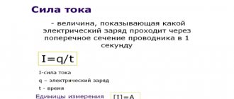
AC power
Within an alternating current circuit, there are three types of power: active type or P, reactive type or Q, and full type or S. In the first case, the standard unit of measurement is the Watt (W or W), and the formula for calculating active power parameters is:
P = U × I × cos φ.
The calculations of positive or negative active power directly depend on the characteristics of the phase shift angle coefficient or the latter indicator.
For reactive type power measurements, a special volt-ampere with the designation “Var” or Var is used.
This value characterizes the loads that are formed inside electrical structures under the influence of oscillations of electromagnetic fields in alternating sinusoidal current circuits.
The calculation is carried out on the basis of root-mean-square voltage and current parameters multiplied by the angular sinusoid of the phase shift, according to the values:
Q = U × I × sin φ.
In conditions of values at the level of 0/+90°, the sine value will be positive, and for values within the range of 0/-90° - only negative. Measurements of total electrical power are carried out exclusively in volt-amperes (VA or V A).
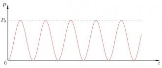
Dependence of power on time for alternating and direct current
The value corresponding to the product of the standard voltage in the clamping area with the indicators of periodic electric current inside the circuit should be calculated in accordance with the formulas:
S = U × I or S = √Р2 + Q2, where
- the P value is represented by active power;
- Q2 value is an indicator of reactive power.
Of no small importance is the complex power corresponding to the impedance. In any case, it must be taken into account that positive power corresponds to P > 0, and negative power corresponds to P < 0.
Large domestic producers of electrical energy generate alternating current with a so-called industrial frequency of 50 Hz and voltage levels in the range of 10-20 kV, and the electrical voltage is increased at special transformer substations.
Active power
To understand how much energy a source consumes, it is more appropriate to take the average power over a period. To do this, let's go back to the first graph.
On the instantaneous power graph, a rectangle with sides T and Pm/2 . The part of the graph that is above the Pm/2 fits exactly into the unshaded part of the rectangle. Thus, using the Pm/2 we can determine the average power over a period, which is called active power . Active power is useful power that is converted into other types of energy.
In our case, the phase shift is zero, so the power factor is equal to unity, but in cases with reactive elements this point must be taken into account.
Active power is measured in watts - W.
cosφ – power factor , which shows the ratio of active power to total power.
AC Power Formula
The power indicators of an alternating type electric current are the product of the current data and the voltage, and the level will be zero in conditions of passing through zero, but necessarily maximum at the peak amplitude.
Despite the complexity of measuring power, it is important to remember that such data are not representative, so from a practical point of view, the active average power in a certain period is of interest.
In a single-phase circuit
For a single-phase circuit, the formula for determining the total power is used: S = U × I , where
- S —indicators of total power characteristics (Ba);
- I is the level of effective electric current taking into account the generator winding (A);
- U - parameters of the calculated effective voltage value in the generator (V).
The full power characteristics taken into account in standard independent calculations affect the dimensions of the generator with variable electric current, which is determined by the cross-section and number of turns of the winding wires, as well as the thickness of the insulating material. For active and reactive resistance, the power consumed in active resistance and in the reactive part is important.
Single-phase AC electrical circuits
Reactive power indicators are caused by energy fluctuations under conditions of the formation and loss of electric or magnetic fields. The electrical energy stored within the field of such resistance is progressively returned back to the generator, which is connected to a standard electrical circuit.
The presence of reactive currents between the reactive receiver and the generator, which have inductive and capacitive reactance, contributes to the useless load of the line and generator, which is accompanied by additional energy losses.
Calculation
To find out the active power indicator, you need to know the total power; the following formula is used to calculate it:
S = U\I, where U is the network voltage, and I is the network current.
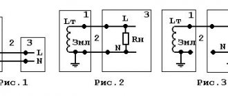
The same calculation is performed when calculating the energy transfer level of the coil with a symmetrical connection. The diagram looks like this:
Symmetrical load diagram
The calculation of active power takes into account the phase angle or coefficient (cos φ), then:
S = U * I * cos φ.
A very important factor is that this electrical quantity can be either positive or negative. It depends on what characteristics cos φ has. If the phase shift angle of a sinusoidal current is in the range from 0 to 90 degrees, then the active power is positive, if from 0 to -90, then it is negative. The rule is valid only for synchronous (sinusoidal) current (used to operate an asynchronous motor or machine tool equipment).
Also, one of the characteristic features of this characteristic is that in a three-phase circuit (for example, a transformer or generator), the active indicator is completely generated at the output.
Three-phase network calculation
Maximum and active power is denoted by P, reactive power by Q.
Due to the fact that reactive is determined by the movement and energy of the magnetic field, its formula (taking into account the phase shift angle) has the following form:
QL = ULI = I2xL
For non-sinusoidal current it is very difficult to select standard network parameters. To determine the required characteristics for the purpose of calculating active and reactive power, various measuring devices are used. This is a voltmeter, ammeter and others. Based on the load level, the desired formula is selected.
Due to the fact that the reactive and active characteristics are related to the total power, their relationship (balance) is as follows:
S = √P2 + Q2, and all this equals U*I.
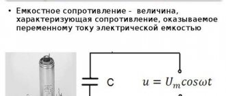
But if the current passes directly through the reactance. There are no losses in the network. This is determined by the inductive inductive component - C and resistance - L. These indicators are calculated using the formulas:
Inductance resistance: xL = ωL = 2πfL,
Capacitance resistance: xc = 1/(ωC) = 1/(2πfC).
To determine the ratio of active and reactive power, a special coefficient is used. This is a very important parameter by which you can determine what part of the energy is used for other purposes or is “lost” during operation of the device.
If there is an active reactive component in the network, the power factor must be calculated. This quantity has no units of measurement; it characterizes a specific current consumer if the electrical system contains reactive elements. Using this indicator, it becomes clear in which direction and how the energy shifts relative to the network voltage. To do this you will need a voltage triangle diagram:
Stress Triangle Diagram
For example, if there is a capacitor, the coefficient formula is as follows:
cos φ = r/z = P/S
To obtain the most accurate results, it is recommended not to round the data obtained.
In a three-phase circuit
The power indicators of alternating current with a uniform three-phase load are determined by the presence of an equivalent current flowing through the conductors of the phase. In this case, the current indicators under the conditions of using the neutral conductor are “O”. Formula for calculating alternating current power under three-phase network conditions: P = 3 × U φ × I × cos(φ).
Symmetrical (uniform) phase load in a three-wire three-phase current circuit
The flow of currents of different magnitudes inside phase conductors represents an asymmetrical or uneven load. In this case, it is the asymmetrical load that is accompanied by the flow of current through the zero or neutral wires, therefore the level of power indicators is determined in accordance with the standard and well-known formula:
Total = Ua × Ia × cos(φ1) + Ub × Ib × cos(φ2) + Uс × Iс × cos(φ3).
Current power through resistor
Therefore, for instantaneous power we obtain:
Rice. 1. AC power through resistor
The maximum value of our power is related to the amplitudes of current and voltage by the usual formulas:
This feeling is absolutely true! The way it is. Of course, we can give a mathematically strict definition of the average value of a function (in the form of some integral) and confirm our guess with direct calculation, but we don’t need this. An intuitive understanding of a simple and important fact is enough:
Rice. 2. The average value of the squared sine is
So, for the average value of the current power across the resistor we have:
In connection with these formulas, the so-called active
(or
effective
) values of voltage and current (in fact, these are nothing more than the
root mean square
values of voltage and current. We have already encountered this: the root mean square speed of the molecules of an ideal gas (sheet “Equation of State of an Ideal Gas”):
The effective values (4) are extremely important for practice. It turns out that AC voltmeters and ammeters show exactly the effective values
(that's how they are designed).
Know also that the notorious volts from the outlet are the effective
value of the household power supply voltage.
Average power in active load
The power parameters of the electrical network or any installation are the most important data of almost any electrical device. The transmission of passing or consumed power characteristics of the active type is carried out over a certain period of time.
Table values of average power characteristics of main household appliances
| Device | Indicators |
| Charger | 2.0 W/hour |
| Fluorescent lamps "DRL" | 50 W/hour or more |
| Electric kettle | 1.5 kW/hour |
| Acustic systems | 30 W/hour |
| Washing machine | 2.5 kW/hour |
| High pressure washing | 3.5 kW/hour |
| Semi-automatic inverters | 3.5 kW/hour |
| Kitchen blender | 1.0-1.2 kW/hour |
| Microwave oven | 1.8 kW/hour |
| Kitchen toasters | 1.2 kW/hour |
| TV | 0.2 kW |
| Fridge | 0.4 kW |
| Vacuum cleaner | 1.0 kW |
| Desktop computer | 0.55 kW |
| Electric stove | 2.5 kW/hour |
| Hair dryer | 1.0 kW/hour |
| Iron | 1.0 kW/hour |
| Electric oven | 1.2 kW/hour |
| Electric heater | 1.4 kW/hour |
Power in the presence of a phase shift between current and voltage
Under conditions of alternating electric current, coincidences in current direction and voltage are noted only in the absence of coil induction and capacitors. In this case, the vector directions of current and voltage are identical. The presence of coils and a capacitor in the circuit is accompanied by the coincidence of current phases and voltage indicators, but vector rotation occurs at the same speed and at constant angle parameters.
The phase shift or shift coincides with the angle that is observed between the vector radii of the current indicators and voltage parameters, and a lag in these criteria provokes a mismatch.
AC current and voltage phase shift
In this case, the power characteristics are negative due to the product of positive and negative quantities. In such conditions, an external type electrical circuit becomes the standard source of electricity. A small amount of energy entering the circuit at positive power values is returned only in the presence of negative values.
The duration of parts of the period directly depends on the level of phase shift, while the displacement indicators are determined by the duration of negative powers, or the so-called average power characteristics of the electric current.
Characteristics
Alternating current flows through a circuit and changes its direction with magnitude. Creates a magnetic field. Therefore, it is often called periodic sinusoidal alternating electric current. According to the law of a curved line, its value changes after a specific period of time. That's why it's called sinusoidal. Has its own parameters. The important ones are to indicate the period with frequency, amplitude and instantaneous value.
A period is the time during which the electric current changes, and then it repeats again. Frequency is the period per second. Measured in hertz, kilohertz and millihertz.
Amplitude is the maximum current value with voltage and flow efficiency over a full period. Instantaneous value is an alternating current or voltage that occurs during a specific time.
Power balance
Independently finding some electrical unknowns, as a rule, requires mandatory verification of the correctness of the obtained values, taking into account the power balance.
In accordance with generally accepted characteristics, the balance in an electrical circuit is based on the law of conservation of energy, therefore the total power consumed and supplied must be equal.
The calculations take into account equivalent resistance indicators and Ohm’s law, familiar to most from physics courses.
Small discrepancies in values are allowed, which is caused by standard roundings carried out in the process of performing independent calculations. Thus, regardless of the level of complexity of the created circuit, the balance must converge, which is a guarantee of maintaining operability and complete operational safety.