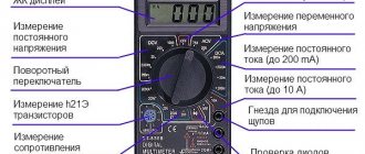
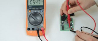
Current along with voltage and resistance is a very important concept in electricity. It is measured in amperes and is determined by the amount of electrical energy passing through a conductor in a certain unit of time. Its value is determined using measuring instruments; at home, this is easiest to do using a multimeter or tester, which is available to many owners of modern apartments. Current control is very important for the operation of mechanisms that depend on power supply, since exceeding the maximum permissible value leads to equipment failure and emergency situations. The topic of this article is how to measure current with a multimeter.
Types of multimeters
There are two types of testers on the modern electrical appliance market:
- Analog.
- Digital.
The main elements of analog instruments are a scale with divisions marked on it, which is used to determine the indicators of electrical quantities, and an arrow-pointer. Such multimeters are in high demand among beginners due to their low cost and ease of use.
But, along with these positive aspects, analog testers also have a number of disadvantages, the main one of which is the high measurement error. It can be somewhat reduced due to the tuning resistor, which is structurally included in the device. However, if you need to measure electrical parameters with high accuracy, it is better to use a digital device.
Wiring type and its parameters
At home, you most often have to deal with alternating current, much less often with direct current.
Typically, direct current is measured in batteries and batteries; house wiring always runs on alternating current. Even if the electrical network is powered by batteries (a backup power source, the main one in the absence of a centralized power supply), it must contain an “adapter” - a device that converts direct current into alternating current. When figuring out how to measure current with a multimeter, you need to clearly understand: to work with direct current, use the DCA (A-) segment of the multimeter, for measuring alternating current, use the ACA (A~) sector. The designations are associated with abbreviations of English terms: direct current amperage (DCA) and alternating current amperage (ACA) is the designation of alternating current on a multimeter.
Typically, multimeters allow you to measure microcurrents - up to 200 mA - and stronger ones (up to 10A). Devices that allow measurements in more powerful electrical networks have an additional socket for a plug (probe) marked 20A. Typically, in models with four connectors, two are designed to measure current in different ranges, one is for other measurements (voltage, resistance).
The COM (COMMON) connector, common (universal) for all types of measurements, is intended for the negative (black) probe of the multimeter.
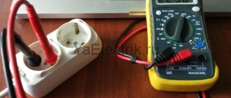
Thus, to measure current with a multimeter, you need to connect the black probe to the COM connector, and the red probe to the socket for checking microcurrents or ordinary currents. For sockets and switches, the device regulator is set to the alternating voltage sector, for batteries and batteries - constant. If the level is unknown in advance, the highest value allowed by the device is selected.
Important: if no energy-consuming device is connected to the outlet (on the switch), the electrical circuit is open and there is no current in it!!! Measuring the current directly in the socket or on the contacts of the switch is useless and dangerous! This causes a short circuit.
Digital multimeters
The only external difference between a digital device and an analog one is the screen on which the measured parameters are displayed in the form of numbers. Old models are equipped with an LED display, while new types of devices are equipped with a liquid crystal display.
They are distinguished by high measurement accuracy and ease of operation, since they do not require adjustment of the calibration.
The disadvantage of these devices is the price, which is several times higher than the cost of analog testers.
Working with a multimeter: from theory to practice
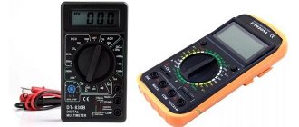
A multimeter is an irreplaceable and simply necessary thing for a radio amateur; without it, as if without hands, it allows us to measure voltage, current, resistance and ratings of radio components, find out the parameters of transistors with diodes, helps in testing circuits, and so on. There are many types of multimeters, from the cheapest and simplest to the most expensive and versatile. They differ in quality, measurement accuracy and, of course, functions. Multimeters can also be counterfeit; it is not very easy to distinguish a fake from an original; the Chinese often counterfeit multimeters from well-known companies. There is no point in talking about the quality, much less the accuracy and service life of such devices.
To work, we will need the most ordinary multimeter, digital or pointer; I will show examples on a digital multimeter model DT838B. These multimeters are widespread, they have many modifications and are sold on almost every corner.
Voltage measurement
Very often, or rather almost always, you have to deal with measuring voltages and current in a circuit. I think it’s clear how to measure voltage; to do this, switch the switch to the AC position - if you need to measure alternating voltage:
or DC – if constant:
Remember, constant voltage comes after the diode bridges, alternating voltage occurs at the terminals of the transformer and in the 220 volt network.
With the measurement limits, everything is also simple, for example, if you need to measure a direct voltage that does not go beyond 20 volts, you set the switch arrow to “20”, then simply touch the device’s probes to the plus and minus of the circuit, and the information will be displayed on the display. If you do not know in advance what voltage there may be on a section of the circuit, set the switch arrow to 200 and measure. When measuring large voltages, do not touch metal parts or the probe itself.
Another little piece of advice, before measuring the voltage, think a little about what kind of circuit this is, what is the approximate voltage in this circuit? Read the labels on the capacitors, what voltage they are for, look at the markings and characteristics of the diodes.
Current measurement
Measuring current, namely measuring large currents, is a rather dangerous process, you should treat it with caution, be extremely careful and do not allow accidental short circuits, otherwise your circuit may fail, and you yourself may suffer!
In order to measure current, you need to have a good idea of what kind of parameter it is and what properties it has. Let's look at the example of a fan from a computer video card; you can take any other fan you have and let's see how much it consumes. First you need to determine to what extent you will measure the current. If you don’t know, then you need to start with the maximum limit.
In order to understand how to measure the current consumption of this fan (and indeed any other circuit), take a look at the diagram below:
From this figure it should be clear that the ammeter (multimeter) is connected in series with one of the power circuits. In order to measure current, switch the multimeter needle to position A (current measurement), in some multimeters they simply write 10A. Then, do not forget to plug the positive connector of the probe on the multimeter into the upper socket, as shown in the photo below. The probe is inserted into this socket only when measuring current; in all other cases, the probes must be inserted into the two lower sockets. When measuring current, the polarity of connecting the probes does not matter.
Connect one of the multimeter probes to one of the fan wires, the second multimeter probe goes to power supply, just like the second fan wire, only when connecting, observe the polarity of the fan, positive terminal to positive, negative to negative, you should get something similar:
The current consumption will be displayed on the multimeter display:
Do not measure large currents for longer than 5-10 seconds; after measurements, do not forget to switch the positive probe back to the middle socket.
Resistance measurement
This function is very useful for measuring the resistance of color-coded resistors. We put the switch arrow in the position you need, depending on what you want to measure, Ohms or kilo-ohms. As you already know, kilo-ohms are denoted by the letter K, and Ohms - either by the letter R, or no letters are written after the numbers.
Let's look at examples of color-coded resistors; I have a lot of such resistors in my set, and very often, before soldering such a resistor into the circuit, I check its resistance, in case they put the wrong value in the bag, and this happens.
If the circuit does not work later, you will never guess that the problem is in this particular resistor. Examples of measured resistances are below.
Resistor 10 kOhm.
Resistor 200 kOhm.
In addition, it is very useful to measure the resistance of the input power supply circuits of devices; if it is in the region of several Ohms, then there may be an error somewhere, some element was soldered incorrectly, check the transistors and diodes, the tracks, if you drew them yourself.
During the measurements, not a single resistor was damaged, and each one went back into its bag.
Continuity of radio components
Some multimeters have a continuity function; on a multimeter this position is usually indicated by a diode icon with a signal, or a signal icon separately. The signal response limit is 50-70 Ohms. Those. if the circuit resistance is less than 50-70 Ohms, the device will beep. It is convenient to ring not only circuits, but also radio components, such as open or short circuit coils, switches, thermostats, etc... If there is contact, the speaker in the multimeter will beep. As for chokes and primary/secondary windings of transformers, as a rule, they rarely ring with an alarm; it is best to check the windings with an ohmmeter (put the switch arrow to measure resistance in position 200, or better yet 2000 Ohms), if the resistance is suspiciously small, there may be interturn short circuit, the transformer will, at best, heat up and produce less voltage. Below is an example, I measured the resistance of the primary and secondary windings of a 20-watt transformer, the secondary at 2x6 volts.
Secondary winding: 1.5 Ohm. Primary: 101.5 ohms.
As I already said, it is convenient to ring different switches, buttons, check whether they are closed or open, which pins are connected to which, and so on.
Checking the thermostat, after checking it turned out that it was open:
The switch of the device can be set to both resistance measurement and “beeper”.
Also, it is very convenient to call diodes, find out where the anode is and where the cathode is:
If the diode is not connected correctly, the display will show zeros.
You can ring the transistors and make sure that it is probably working:
You need to call the base with the collector, and the base with the emitter.
You can check the gain of transistors; to do this, insert them into a special pin connector, being careful not to confuse the structure and pinout of the transistor. We set the switch arrow to the hFE position. In this mode we test the transistor's ability to amplify the input signal. Two individual and completely identical transistors can have different values of this coefficient.
As already said, different multimeters have different functions, expensive ones have more functions. Some similar multimeters have a temperature measurement function; an additional cord with a thermocouple is attached to them; this function is useful for finding out the heating temperature of radiators, radio components, etc.
Multimeters are usually very reliable, and it is quite difficult to burn them, but it is possible. For example, if you touch a voltage source of several kilovolts with the probes, the microprocessor of the multimeter will then fail, become very hot, and strange symbols will be displayed on the display.
Precise measurements for you, bye!
Tags:
- Multimeter
Design Features
Regardless of the number of sockets in the multimeter, any of these devices has two types of outputs, which are indicated by different colors. The common output (ground) is colored black and is designated either “com” or “–”. The output intended for measurements (potential) is red. Any of the measured parameters of the electrical circuit can have its own socket.
There is no need to be afraid of confusing it with others, since each of these slots is designated by the corresponding unit.
Another external element of the device is a handle for setting the measurement limit, which can rotate in a circle. On digital multimeters these limits are greater than on analogue ones, in addition, they may include additional options, for example, a sound signal and others. Since we are talking about how to measure current using a tester, we will talk about a scale with amperes.
Each multimeter has its own maximum current limit, and when choosing an electrical network for testing, the current strength being tested in it should be compared with the limit for which the device is designed. So, if the current flowing inside the electrical circuit is 180 A, it is not recommended to carry out measurements using a multimeter rated at 20 A, since the only result obtained will be the device burning out immediately after testing begins. The maximum limit is always indicated in the multimeter data sheet or on the device body.
Devices used
Current strength can be measured in various ways, but not all of them are applicable in everyday life. For example, various instrument transformers connected to a circuit are extremely inconvenient to carry around the house and even store on a shelf in the garage. Therefore, current measuring instruments are ammeters, multimeters and clamps. Next, we will consider in detail the features of the operation and application of each of them.
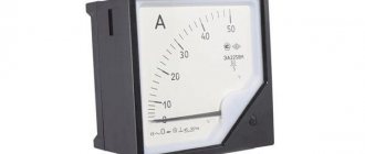
Ammeter
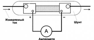
This is one of the simplest measuring instruments that responds to changes in current load. From an electrical engineering point of view, an ammeter represents zero or infinitesimal resistance. Therefore, if voltage is applied only to the device, a short circuit current will arise in it, due to which the ammeter is connected in a circuit in series with the load being measured. For clarity, it is worth explaining that it is impossible to measure the current in a socket, since without a load (in the case of an open circuit) no current flows in it, only voltage is present at the socket contacts, so connecting an ammeter will directly lead to a short circuit.
Electric current refers to the directed movement of charged particles that passes through the cross section of a conductor in a certain unit of time. Therefore, remember that the current load arises only from turning on the household electrical appliance to the power source. Connecting an ammeter separately to a power supply point or separately to a working two-terminal network will in no way provide information about the current strength. If we look at the example in the diagram, then in order to measure amperes you must connect the device in line in series with the object being measured:
Rice. 1. Example of connecting an ammeter
As you can see, the main difficulty lies in the fact that the measurement process occurs directly at the moment of flow of electrical energy, therefore, there is a high probability of electric shock in the event of a technology violation.
To avoid disastrous consequences, you must follow these rules:
- Connection is made only when there is no voltage;
- The measuring wires must be insulated, and the connection points must be removed from humans; if necessary, the possibility of touching them must be excluded;
- The ammeter is also removed from the current measurement circuit when the voltage is removed.
Since the ammeter is a narrowly focused device for measuring current, rarely does anyone keep it at home. Therefore, if you want to purchase a device, it is much more profitable to get a multimeter, which has much wider functionality.
Multimeter
This device is also called a tester, Ts-eshka, so in everyday life you can find different generations of a multimeter. The principle of using a multimeter as a means for measuring current in a circuit is completely similar to an ammeter, both in terms of the connection diagram and the precautions taken. However, it should be noted that a multimeter is different from a multimeter, so before turning on the tester, be sure to see if it is suitable for measuring the current in your case.
Of the design features, we immediately note:
- Measuring range – set by a switch to a certain current value. It is chosen so that the expected load does not exceed it, but is comparable.
- The type of current is alternating or direct; note that some models of multimeters provide the ability to measure only one option.
- Separation into low-current and power measurements - such devices have a separate scale for mA, µA and a separate one for A. They can also have separate connectors to connect probes.
- The presence of overload protection when connecting measuring devices is indicated by the mark unfused . Which indicates the presence of a fuse that can prevent the multimeter from malfunctioning from the flow of excessive current.
According to the method of displaying information, all multimeters are divided into dial and display. The first of them are a rather outdated model; only experienced electricians familiar with the basics of metrology can navigate them. A beginner may get confused about the readings on the scale, the division value, or what units the load is measured in. Therefore, using a digital device is much simpler and more convenient; a specific number is displayed on the display.
Clamp meter
This is the most convenient device, since in order to measure the current strength with a clamp meter, there is no need to break the circuit. Structurally, the clamps are a detachable magnetic circuit into which the conductor on which you want to measure the current is placed. Current clamp meters are similar to the same multimeter, and in more advanced models you will find the same switch with the function of determining power, voltage, resistance, current and connectors for connecting probes.
The procedure for preparing the device for measurements
The multimeter switch must be moved to sector A (DA for direct current or CA for alternating current), which corresponds to the current measurement, selecting the desired limit. Some modern testers for DC circuits have one position, and for alternating current - another. In order not to make a mistake, you need to be guided by the letters on the front panel.
They are the same in any device, you just need to understand what value each of them represents.
All multimeters are equipped with two cables, at the end of each of which there is a probe and a connector. The second ends of the wires are inserted into the sockets of the device, which correspond to the current measurement, in our case, current strength.
Charger and adapter measurements
Battery rechargers and power supplies are used with many modern gadgets. True, their purpose is different. Power supplies are designed to convert voltage to one suitable for the operation of the connected gadget. The charger is used to replenish batteries with electricity. It is necessary to know their characteristics in order not to damage an expensive device in case of failure of a standard device.
So, to measure current values in a circuit with an adapter or charger, you need to set the measurement limit in the range from 1 A to 10 A. The multimeter is connected in series to the circuit. If the readings are zero, you need to swap the probes or clamps.
Measurement order
A multimeter for measuring current is connected to an open circuit. This is the main difference from the voltage measurement procedure, in which the tester is connected to the circuit in parallel. The indicator of the amount of current that passes through the device is displayed by an arrow on the scale (if we are talking about an analog device) or is displayed on the liquid crystal (LED) display.
There are different ways to break the circuit under test to connect the device to it. For example, by disconnecting one of the terminals of the radio element using a soldering iron.
Sometimes you have to cut the wire with wire cutters or pliers.
When determining the current value of a battery or accumulator, such a problem does not exist, since a circuit is simply assembled, one of the elements of which is a multimeter.
How to measure current with a multimeter: main points
All types of current are measured using different methods inside the measuring device. Therefore, the tester always has an element with which the desired mode and range are set. In more advanced models, the range is determined automatically.
To select a mode, you usually only need to turn the knob to one of the following values:
- Direct current: A -, DCA, I -;
- Variable: A ~, ACA, I ~;
We strongly advise you to read the instructions for the multimeter, which contain the symbols available on the tester. They may vary depending on the model. An article on how to use a multimeter will also be useful.
Please note that to measure current with a multimeter you will have to create an open circuit! This is the main difference between this test and measuring, for example, voltage, when the multimeter should be connected to the circuit in a parallel circuit.
Masters break the circuit under test in different ways. To include a limiting resistance in the circuit, resistors are also used, but most often ordinary light bulbs.
Please note that breaking the electrical circuit must be done before starting measurements with the voltage turned off!
What to consider when measuring
An important condition when determining the current strength is the inclusion of a limiting resistance in the circuit - a resistor or an ordinary light bulb. This element will protect the device from damage (combustion) under the influence of electron flow.
If the current strength is not displayed on the indicator, this indicates an incorrectly selected limit that needs to be reduced by one position. If there is no result again, do one more, continuing until some value is displayed on the screen or scale.
The measurement must be taken quickly - the probe should not be in contact with the cable for more than one or two seconds. This is especially true for low power batteries. If, while measuring the battery current, you hold the probe on the wire for a long time, the result will be their discharge - partial or complete.
How to check voltage with a multimeter
DC voltage measurement
As you know, there are two types of voltage: alternating and constant. Any multimeter has at its disposal the functions of measuring direct and alternating voltage. To measure the voltage, we must touch the leads of the power supply with the probes. As you can see, it is advisable to connect the minus of the power supply to the minus of the multimeter (COM-black probe), and the plus to the red probe of the multimeter.
measuring DC voltage using a multimeter
In order to measure DC voltage, we must set the switch to the “=V” icon or similar. Let's measure the voltage on the battery, since the battery produces a constant voltage.
To do this, set the switch on the multimeter to measure DC voltage. For a more accurate measurement, I set the range to 20 Volts. We touch the battery with the probes and look at the value on the display. 1.28 Volts, which is considered normal for a nickel-manganese battery.
In order to measure the voltage on any chemical current source, we simply set the range we need, then make sure that the probes are in their places (black on COM, red on V) and then touch the terminals of the battery, accumulator or any other current source.
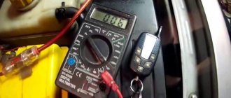
Here, for example, I measure the voltage on a car battery.
You can also measure the voltage from a laboratory power supply that produces direct current. Let's demonstrate what it all looks like. I set the voltage on the power supply to 10 Volts and measure this voltage with a multimeter.
measuring DC voltage from the power supply
But what happens if we reverse the polarity? That is, we connect the red probe of the multimeter to the minus, and the black probe to the plus? The digital multimeter in this case will simply show a minus sign.
In modern multimeters, this icon is already combined with the AC icon and looks like this:
combined icon of direct and alternating voltage Here, using the function key, we ourselves choose what current we will measure: direct or alternating. Direct current is designated DC - direct current, which literally translated from English is “direct current”.
function switching key
In the example below, I measured the voltage on a lithium-ion battery.
AC voltage measurement
To check the alternating voltage, we must set the functionality selection switch to the “~V” icon. I think you are aware that the voltage in the outlets in your home is variable. Let's measure its value. As you can see, the multimeter showed 215 Volts, although it should be something around 220 Volts. This voltage is still within the operating range, so everything is fine.
For a multimeter with automatic range measurement, we need to select the AC icon on the display of your device using the FUNC key. AC - alternating current, which literally translated into English is alternating current.
This is how the voltage in an outlet is measured. 228 Volts, which is also quite normal.
Safety precautions
As you can see, the procedure for measuring current using a multimeter is not difficult. It is only important to follow the instructions and do not forget about strict adherence to safety measures:
- Before taking measurements, turn off the power supply.
- Check the cable insulation - with prolonged use, its integrity is sometimes compromised, and the likelihood of electric shock increases significantly.
- Work exclusively with rubber gloves.
- Do not take measurements in high air humidity. The fact is that moisture has high electrical conductivity and the risk of damage also increases.
- A person who has suffered an electric shock needs medical attention. If possible, it is better to carry out any work with electricity, including measurements, together. In an emergency situation, the presence of a partner can be a real salvation.
Having completed the measurements, the cut cables must be reconnected, having first de-energized the circuit again.
In detail and clearly about measurements carried out using a multimeter in the video:
Principles of measuring current with a multimeter
Measuring current with a multimeter is not difficult, but there are certain rules that should not be neglected:
- The electrical network must be de-energized.
- Cables must be well insulated, otherwise the risk of electric shock increases.
- Operate the meter wearing gloves that do not conduct electricity, such as rubber.
- Do not try to determine the current when there is high humidity, because this also increases the risk of electric shock.
- Measure quickly so that the probes do not connect to the wires for more than 1-2 seconds. This is especially important if you are going to work with low-power elements. For example, if you use a multimeter to measure the battery current and hold the probes for a long time, they will be completely or partially discharged.
We recommend that you carry out all electrical work with a partner who will provide first aid/call an ambulance if an emergency occurs.
Current measurement examples
To understand the principles of measuring current in various electrical appliances and circuits, options for devices and methods for measuring current are given below.
Electric motor
Current measurements in the motor windings are made to check for short circuits, faults and to set up the correct motor control algorithm. Since the current in a three-phase asynchronous motor is the same in each phase, it is enough to connect one ammeter to one phase to check its consumption.
To diagnose each of the windings, the current in each phase is measured, and if it is different in each of the phases, then an interturn short circuit is possible in one of the windings, and if there is no current in one of the phases at all, then there is either a break in the line or a break in the winding . If there is current in one of the phases, but it is less than in the other two, there may be poor contact in the circuit breaker or in switching devices.
With a single-phase electric motor, everything is simpler: the current is measured in a single phase. But you need to keep in mind that the maximum current of the ammeter is limited and is usually no more than 5A, so for high currents, current clamps or other circuits with current transformers and an ammeter are used.
Welding machine
In order to understand which electrodes to use and in what mode to carry out welding work, you can measure the current strength on the output wire of the welding machine under load. The measurement is carried out similarly to other devices, including an ammeter with a transformer in the circuit on the welding inverter (there are also older models of ammeters with the ability to measure up to 200 A) or using a current clamp.
Batteries and accumulators
In everyday life, it is often necessary to measure the current of an electrical appliance that runs on batteries (batteries can be crown batteries, AA batteries, and other batteries). It is important to understand that you cannot simply connect a multimeter or ammeter to the source, because the current strength is measured only under load.
As a load, you can use an incandescent lamp or a resistor, or be connected to the circuit of the device itself. To measure, you need to select the required mode on the multimeter (for measuring direct current), correctly connect the terminals to the device and on the circuit section. In this case, on the screen we will receive the desired value for the load that is connected to the battery.
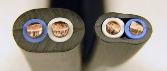
Testing with a multimeter
The multimeter has several more functions, one of which is the so-called continuity test. It is used to search for a break in the neutral wire in an electrical circuit.
Algori:
- connect the red probe to “V/Ω”, the black one to “COM”;
Testing wires with a multimeter to check their integrity Source avatars.mds.yandex.net
How to use a multimeter when measuring AC voltage.
Measuring alternating voltage is carried out on the same principle as measuring direct voltage.
Switch the device to AC voltage measurement mode by selecting the appropriate AC voltage measurement limit.
Next, connect the probes to an alternating voltage source and take readings from the indicator.
How to determine the current strength in a 220V outlet?
instrument.guru > Electricity > How to determine the current strength in a 220V outlet?
Almost any premises, whether residential or industrial, are equipped with sockets for connecting electrical appliances.
For stable and safe operation of electrical appliances, it is necessary to know not only the voltage in the network (standard 220 volts), but also the current strength for which the outlet is designed.
It should be noted that this electrical equipment itself does not have any current strength; it only withstands a certain amount when connecting any household or industrial equipment.
Methods for determining current strength
- The device is an ammeter .
An ammeter is a measuring device that determines the current strength and displays it on an existing scale. To do this, you need to connect a closed circuit in series: a socket, a unit of household appliances, an ammeter and again a socket. Instead of an ammeter, you can use a multimeter - a combination device that includes a voltmeter, ammeter and ohmmeter. The error in current measurements on a specific section of the circuit will depend on the accuracy class of the measuring device. - By calculation method.
To apply the calculation method, you need to know the power value of the connected device.Taking into account that in our country, the main part of the premises is supplied with a standard voltage of 220 volts, the current strength in a 220V outlet can be calculated using the following formula:
I = P / U, where I is current (ampere); P – power of the electrical appliance (watt); U – network voltage (volts).
This method determines how many amperes are in a 220V outlet. For example, using the formula, you can calculate what current is in a 220V outlet when connecting a conventional electric kettle with a power of 2.5 kilowatts or 2500 watts. The resulting value is 11.36 amperes.
Current characteristics
When calculating the amount of current that the outlet supports, it is necessary to clarify the current characteristic. There are two of them: direct current and alternating current.
Variable is most widespread in the field of electricity consumption, since its losses during transmission over long distances are significantly less.
If necessary, conversion is carried out using circuits of consumer devices. Thus, the outlet supports alternating current of 220 volts.
Types of electrical outlets
Equipment used in everyday life has different power characteristics, therefore, the electrical fittings in the premises must be appropriate. Today's household devices are more powerful than older technology.
Just 20 years ago, an outlet limited to 6 amps could be used for all devices. This connector was intended for equipment with a power of up to 1.5 kilowatts or 1500 watts. This is not enough for modern life.
Currently the load limit is:
- 16 amperes for ordinary premises, which guarantees the safe operation of consumers with a power of up to 3.5 kilowatts;
- 25 amperes for apartments or houses where electric stoves with a power of up to 6 kilowatts are installed. Such sockets are called power sockets;
- 32 amperes at increased loads on the network, for example, when connecting several powerful ovens or stoves in production. In this case, a three-phase cable is used, which is designed for 380 volts. Accordingly, the sockets must also be three-phase. This equipment differs in its design. If there is an increased load on the network in a private home, in addition to installing special equipment, reinforced electrical wiring is also required.
The need for automatic power off
A circuit breaker is an important element in the electrical supply system of a room. There are special devices on distribution panels that indicate how many amperes of the maximum allowable current. Typically, 16, 25 or 32 ampere circuit breakers are installed for household purposes.
It is recommended to install its own circuit breaker for each powerful device. For example, an electric stove has a power of 6 kilowatts or 6000 watts, therefore the current will be 27 amperes at a voltage of 220 volts.
In this case, you need a larger circuit breaker, namely 32 amperes.