Any person who is at least somewhat interested in household chores and everyday life has an idea of why you need a soldering iron, drill, construction mixer or jigsaw at home. But the device that will be discussed below is not found in every home, because this device is an electrician’s pliers. Despite this, they can serve anyone well. They are very easy to use, unfortunately I just don’t know everything about their existence. This compact device is not only an indispensable assistant, but also a reliable friend of any owner.
What it is
Electric clamps directly serve specialists for prompt and reliable measurement of various parameters of electric current: its voltage, power and others. In this case, there is no need to break the chain or disrupt its operation. Depending on what values need to be measured, the following mites are distinguished:
- Ammeter;
- Ampere-voltmeter;
- Wattmeter;
- Phase meter.
Current clamps
This measuring device in any configuration - from the simplest to the most professional - consists of a magnetic core, a button that records measurement data, a switch (for selecting the measurement range and the necessary additional functions of the device), various connectors for additional connection of probes and a small built-in monitor/ display.
Current clamps
The most popular and also easily applicable are clamp-on ammeters, used to obtain the parameters and characteristics of alternating current; they are also called current meters. Let's figure out why current clamps are needed.
Electrical clamps easily allow you to:
- Determine and control actual loads in electrical networks;
- Measure the power of various electrical appliances;
- Monitor the operation of electricity meters and its consumption (for example, to verify electrical meter readings).
Such current clamps can be used at voltages up to 10 kilovolts.
Application benefits
The advantages of current measuring clamps include:
- Ability to measure electric current without disconnecting the circuit;
- Small device dimensions;
- Ease of measurement in high-voltage circuits.
Thanks to current clamps, it is also possible to record very high currents. Before purchasing this electrical device, you need to carefully familiarize yourself with its characteristics.
It is better not to save on tools, but to purchase only high-quality devices, based not on cost, but on the popularity of the brand.
What do clamp meters measure?
Before purchasing this device, you need to decide for what purpose the electrical clamps are intended.
They are a transformer with a connected ammeter. The device itself is the primary winding of the transformer. Placing a conductor inside it helps induce an electric current into the winding due to the resulting electromagnetic field. Then it goes to the secondary winding of the coil, the readings from which are read by an ammeter. The readings of this device are recalculated adjusted for the transformation ratio indicated on it. A transformer does not work with direct current, so the current clamps described are for alternating current.
Clamp meters manufactured today are used for values measured at direct current. A Hall sensor is placed in place of the ammeter, which detects the presence and voltage of the electromagnetic field.
Using these devices, the following measurements are made:
- actual network load;
- the accuracy of readings of various equipment intended for electricity metering, comparing the readings on them with the readings obtained when measuring with clamps;
- power of household and professional electrical appliances.
Current clamps for direct current are more expensive than their counterparts for alternating current, but they are more accurate and have improved quality indicators. The tool, used in conjunction with a digital multimeter, allows the user to save the user from calculating the desired value, since the device has a built-in calculator.
conclusions
All three devices work, all declared characteristics correspond to real ones.
ICartool IC-200A
Suitable for those who have a multimeter, but lack the function of checking the consumption of electrical appliances. Advantages: compactness and price. The disadvantages include the low quality of soldering.
ICartool IC-206В
– a device with balanced characteristics. Having such a device at home, a multimeter is no longer necessary. By and large, in order to become universal, it only lacks a current measurement function. But for this case there is another model.
ICartool IC-206D
- a universal device. Strengths – measures everything. Disadvantages - strange behavior in duty cycle measurements.
The advantages of all three devices
- good cases. Fairly accurate measurements. Rich functionality of older models.
Disadvantages of all three
– the dialing mode is not very convenient and the screen is not visible from all angles.
Topic: Current clamps
Working principle of clamp meters
The principle of operation of electrical clamp meters is in many ways similar to the operation of a substation - there is an instrument transformer and a device for measuring electrical parameters: current, voltage, etc. As you know, any transformer, including a measuring one, consists of two or more windings.
In electrical measuring clamps, the first winding is a conductor, the current strength of which we measure. The second winding with a large number of turns is located in the tongs themselves. The device analyzes the current in the secondary winding and, taking into account the known transformation ratio, calculates the amount of electric current in the conductor.
In the figure below you can clearly see the operating principle of this measuring device.
It is worth noting that measuring current with electrical measuring tongs is not a difficult and very convenient task. You just need to set the required value on the handle, open the handles, pass the conductor through the pliers and release one handle.
Design of Dietze pliers
Any current clamps differ from each other in design and color scheme, while their basic design remains unchanged. After all, they are all made according to the principle, which is based on an identical scheme. Without fail, clamps for measuring current consist of a magnetic core, a bracket, a range regulator and a button for recording readings. Dietze clamps can also be equipped with a screen, and more modern or technically improved models have an internal transformer with a diode bridge. The clamps-magnetic core is nothing more than a secondary winding, and the clamps themselves are a detachable element.
Types of current clamps
The types of mites depend on the appearance, design and type of output. They are usually divided into the following categories:
- Analog or pointer. They consist of a transformer with one turn and a measuring apparatus connected to the secondary winding. Such devices are cheaper and more visual, but have increased sensitivity to mechanical influences and vibrations. Analog meters are typically rated for a specific frequency;
- Digital or electronic. In them, readings are displayed on a digital display using microprocessor calculations, and can be configured to display various values;
- Multimeter. This is a universal tool for measuring all electrical parameters. In it, the pliers can be built directly into the body. The functions and characteristics of a multimeter are determined by its price and model. Often they have the same Hall sensor;
- Clamps for high-voltage networks. Their main purpose is to measure current parameters in networks whose voltage exceeds 1 kV. This type has increased protection and insulation and can be attached to dielectric rods to prevent the electrician from getting too close to the network.
Connection diagram for a multimeter for measuring electric current
Terms of use
Due to the fact that such work is carried out without relieving the voltage, there is a risk of electric shock to personnel; when performing any manipulations with insulating clamps, workers must follow certain rules. Thus, work in devices with a supply voltage of more than 1 kV requires the use of dielectric gloves. Which act as an additional means of preventing electric shock in the event of an insulation breakdown, or other malfunctions of technical equipment, errors by the workers themselves, etc.
Figure 3: Safety precautions when using insulating clamps
Also, in circuits of more than 1 kV, when working with insulating clamps, it is imperative to protect the organs of vision from small hot particles. Which can fly off as a result of heating the metal when the arc burns and can cause injury. For this purpose, personnel are required to wear face shields or goggles made of non-flammable materials. When working in devices up to 1 kV, eye protection is not required, but may be used subject to the requirements of any local or industry regulations.
When carrying out any manipulations, insulating pliers should only be used at arm's length, regardless of the voltage class. Touching or reaching above the limit stops is strictly prohibited. Since the pliers in this case are not able to provide the declared electrical strength standard for a given voltage class, which can lead to electrical injury.
It is strictly forbidden to use insulating pliers if work is performed in the rain, in conditions of thick fog, or any precipitation. The same applies to rooms with high humidity, where a conductive layer of moisture can form on the insulating elements. In such situations, switching or other operations should be performed only with the voltage removed after mandatory grounding with stationary devices or portable grounding using operating rods.
Before starting work, the responsible employee must inspect the insulating clamps for any damage, contaminants and other factors that reduce the protective properties. Test dates must be checked; it is never allowed to use pliers with an expired test date. He should also inspect the sponges for integrity.
Measurement modes
There are 2 methods for determining current strength:
- direct;
- indirect (inductive) measurement.
The first method is carried out by connecting an ammeter to an open circuit. An electric current passes through the device, information about the value of the I value appears on the display.
Advantages of this method:
- measurement accuracy depending on the class of equipment;
- ease and accessibility of measurements.
Flaws:
- it is impossible to measure large amounts of electric currents due to the design features;
- without a break it is impossible to measure the parameters of the circuit;
- measurements are performed only in the circuit that is connected to the device.
How to measure current using a transformer
When a conductor is passed through the terminals of the device, current passes through these terminals, acting as the iron core of a power transformer. Next, the current flows into the secondary winding, which is connected through the meter input shunt. Due to the ratio of the number of secondary windings to the number of primary windings wound around the core, the current entering the input is much less. Typically, the primary winding consists of one conductor, around which the jaws are clamped.
If the secondary winding has, for example, 1000 turns, then the current in the secondary winding will be 1000 times less than that flowing through the primary winding. Thus, 1 ampere in the conductor being measured will produce only 1 milliampere at the instrument input. By increasing the number of turns in the secondary winding, powerful currents can be easily measured.
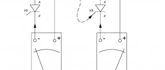
How to measure direct current, because it flows through conductors with a fixed polarity? Here the magnetic field around the conductor does not change, and it is impossible to record the corresponding readings in the usual way. Therefore, the clamps around such a conductor are closed with some gap (see Figure 2).
New Products
Current clamps have been released that allow you to measure the strength of alternating and direct currents - a non-contact method, thanks to ferrite inserts and electromagnetic induction.
The device is in demand in auto services, electrical installation work and in the power industry.
For example, digital products of current clamps UNI -T UTM1230C, current measuring models of clamps Accta AT-1000A, digital three-phase current clamps UNI-T, clamps Mastech M266F, device UNI-T UT203.
Measurement with DC and AC clamps
To measure different types of current using clamps, exactly the same technique is used. The main thing is to pre-select the required operating mode.
Before using the device, you must ensure that the device is not affected by any external voltage sources.
For example, the results of the device can be distorted by some asynchronous electric motors, certain types of transformers, welding machines, and also power supplies (pulse). All of them can realize large fields with electromagnetic waves, which can induce an induced emf in the magnetic circuit.
To measure current using clamps you need:
- Moving the switch knob to the required position.
- Inserting a conductor into the magnetic circuit space.
- Reading results from the device display.
Thus, no special skills or knowledge are needed to work with ticks. Newer models have a special IFLex sensor, which is used for measurements in very cramped conditions.
If you start analyzing two conductors together, their magnetic fluxes should add up together. The display will show the overall result. For example, currents in phase and zero without leakage are equal in magnitude and opposite in value.
In such situations, the device should show a zero result. If it has any significance, we can talk about serious problems in the electricity network.
ICartool IC-M206B
The functionality of this device is noticeably superior to the younger model. It’s easier to say how it differs from the older model in the line. AC current measurement only. Everything else is like the flagship. Namely, the device can measure:
- Alternating current up to 600 A.
- Frequency up to 10 MHz.
- PWM duty cycle.
- Temperatures up to 1000 °C (as stated).
- Voltage at the pn junction of the diodes.
- Capacitor capacity.
Plus, there are additional functions of a low-pass filter, low-resistance voltmeter and non-contact voltage detection, which we, of course, will also check. Yes, and also a flashlight!
The box is similar to the younger model, but the size is slightly larger.
There is a case in the box. Yes, this is a completely different price level, one might say – a “luxury” package. It would be convenient to carry the case by the strap, but it is a little short. Instructions in the pocket, probes, thermocouple, batteries and the device itself.
Probes
this is more serious than the IC‑200A.
Marking of the third category, tolerance up to 600 volts. There are “socks” at the tips for measuring in places where you can accidentally shorten.
Measuring resistance
:
Current 2 A, voltage drop across a pair of probes 0.271 V. Pair resistance 0.136 Ohm. Five times less than IC‑200A. Such probes can already be used to measure currents.
Let's move directly to the device. It has the same style as the IC‑200A, but is slightly larger. Plastic red and black. White lettering on black plastic is easier to read. The program wheel has a handle, so you can rotate it either with the hand that holds the device or with the other hand. Using the same handle it is convenient to determine the selected measurement mode. It would be nice if there was a contrasting arrow on the handle, but it’s already better than on the IC‑200A.
The key is pressed quite hard, but good closure is necessary for accurate measurements, so you have to put up with it. The opening of the jaws is such that any conductor of reasonable size will fit into the throat. On one jaw there is a “beak”, which is convenient for pushing the wires apart and highlighting the desired wire among others. A flashlight shines directly inside the jaws. The grip is quite comfortable. Both the key and the mode switch are right under the right fingers.
But the screen, too, like in the IC‑200A, has its own “dead corners”.
And the backlight, come thunder, turns itself off again. These are perhaps the two most serious shortcomings that catch your eye even before testing the device.
DC voltage is measured with automatic ranging. ION levels are determined as follows.
2.5V:
5.0V:
7.5V:
10V:
As you can see, all levels are measured with an error of within 0.1 volt, which is more than enough for a household appliance.
Calling.
The behavior in this mode is a little strange. Here's a video:
When connecting the probes, the buzzer sounds almost immediately - the delay is within 1/60 of a second. The signal lasts 0.5 seconds, by the end of this interval the screen already shows some resistance value. Then there is silence, and over the next second the value of the measured resistance decreases and approaches the real one. After 1.25 seconds of silence, it drops below 30 ohms, immediately the screen lights up amber and the buzzer resumes. The diagram with such pauses is not very convenient for perception, but, admittedly, it is informative.
Frequency measurement only works for a signal with zero average value. If yours is not like this, the DC component will have to be suppressed with a decoupling capacitor.
Up to one and a half megahertz, the readings correspond well to the real ones; I did not check further.
The duty cycle is tested at frequencies of 100 Hz and 1 KHz.
Everywhere the device accurately found the desired value, up to 99%, which is very good.
Capacity
the device measures in a very wide range: up to 0.1 F. Small values are measured quite quickly.
But the device has to work hard on large electrolytics:
He thought about this instance for 8.2 seconds.
The device measures resistance much faster than capacitance.
This powerful resistor was subdued in less than 2.5 seconds.
Moreover, time is inversely proportional to the resistance value.
The megaohm resistor was identified in less than a second.
All these measurements are quite comfortable for the user and correspond to the nominal values with the accuracy stated in the instructions.
LowZ
– an interesting feature that is not found in every device. First, I will talk about one problem that is familiar to electricians. We take a three-core cord - phase, zero and ground. We insert it into the socket without a grounding contact. Thus, we have two wires under mains voltage, and the third is hanging in the air because it is not connected at both ends. There we have 0 volts, right? Can I touch it with my hands, won't it hit me? Let's look:
Wow! Between one contact and grounding there are 70 volts.
And between zeroing and the other - even more - 82 volts! The device even lit up the screen, warning of high voltage. Where is it from? This is interference from neighboring wires. The clamps have such a high impedance that the charge does not flow to zero, but naturally affects the voltmeter readings. Now we switch the device to LowZ
. It is just for such cases.
3.1 volts between grounding and one working contact.
3.6 volts between ground and other contact.
Now it is clear that what we saw in the mode of a conventional voltmeter is interference that is not capable of causing harm to a person. We tested this on a cord one and a half meters long and without current load. And when examining extended chains, this mode is what is called “must have.”
The measurement showed that in the regular voltmeter mode the device has an input resistance of 11 MOhm, while in the LowZ
input impedance is only 293 kOhm.
Diode testing involves determining the voltage drop across the pn junction. The most significant difference is when checking LEDs. The potential difference at the anode and cathode when the diode opens directly depends on the emitted wavelength. Some people believe that quantum physics is some kind of abstraction. In fact, it is all around us, even in a simple LED. Max Planck proposed a relationship between wavelength and energy. The wider the bandgap in a semiconductor, the greater the photon energy and the shorter the wavelength. Let's check.
Hooray! Physics works! The first LED with the lowest voltage drop is infrared. We don't see its light at all. And the last one is ultraviolet. It has the highest wave energy and the largest voltage drop.
Flashlight.
Everything is simple here. Long press the light button - it turns on. Second long press – turns off. Or you can turn off the entire device - turning on the flashlight is not remembered. The flashlight shines directly between the jaws of the ticks, slightly above the middle in height. The light is white, with a slightly blue tint. Not very bright, but enough to see where you are climbing. In real life, the backlight looks something like this:
Temperature measurement
produced by a K type thermocouple, which is supplied in the kit. Of the thermocouples I have, this one has the softest wire. It’s pleasant to work with it, there is no “springiness” that we had to fight with when measuring temperature with other devices. The temperature readings are plausible at points 36 and 220 degrees, the rest of the range was not measured.
Non-contact voltage detection
works. This cannot be said that this is such an accurate method - even the description stipulates that its readings are not enough to calmly grab bare wires. But it will help you quickly determine which outlets have electricity and which do not, or whether there is a heated floor under the floor covering. Gives a rough idea of where the wire is laid in the wall.
Opening.
Two self-tapping screws, one is visible from the back side with the naked eye, the second is accessible from the battery compartment.
Labyrinth around the perimeter. The battery contacts are connected to the board by springs. The main chip here is packaged, not in a droplet.
This is all I list the advantages. The device is made on the DM1106EN controller. An advanced modern version of the well-proven DTM0660 chip. It contains many excellent multimeters and there is hope that this one will be no worse. The soldering quality is good, but the flux is not completely washed off in some places. Thermistors at the input no longer pile on top of each other in a threatening manner. There are no fuses, but the device has a fairly high input impedance, so thermistors are quite sufficient for protection. There are a lot of unsoldered elements on the board. The board must be unified with the older model.
How to improve measurement accuracy
When measuring a small current, wind the conductor (in which the current is measured) several times around the magnetic core. In this case, the total magnetic flux increases in proportion to the number of turns and the display also increases. Divide the reading value by the number of turns and get an accurate value even for small currents.
Recommendations for selection
To ensure that none of the workers subsequently becomes a victim of electric shock and the culprit of an accident at an electrical installation, adhere to the following recommendations.
- To purchase current clamps, contact a specialized electrical and electronics store, where experienced consultants will tell you which clamps are suitable for solving specific problems. Their experience can prevent mistakes, the consequences of which could be disastrous.
- First of all, decide what kind of current you will work with. AC/DC markers indicate that the tool is universal, DC is only for direct current on the line, AC is only for alternating current.
- Decide what power range you will be working in. Perhaps your choice is in circuits and lines with a maximum power of, say, up to 25 kW, then you are unlikely to need current clamps with a power of 500 kW if there is a product on sale for 50-100 kW.
- Decide what the diameter of the wires on which the power is measured is. Perhaps you will work on wires with a cross-section of up to 15 mm2, then you do not need larger pliers, where the cross-section size reaches 50-100 mm2, if the size on sale is 15-25 mm2.
- If we are talking about digital clamps or a device model for direct current, decide how it is more convenient for you to read the measured current: by reading in milliamps, millivolts or volts.
- Make sure that the materials of the insulating handles and the coating of the pliers do not conduct current. It should be high quality plastic, rubber or composite.
- Check the warranty service life of the pliers, make sure that in the instructions the manufacturer has indicated parameters whose value ranges include those that you need for safe and trouble-free operation.
- Refrain from purchasing pliers at too high a price - not all of their functions may be useful to you.
- If the work is mainly carried out in garage-domestic conditions, and not in production, then give preference to inexpensive pliers, from which you only need to successfully solve your specific problems. Pliers in a low price range are equipped with the function of testing lines and sections of chains.
- Avoid cheap Chinese counterfeits, which have a strong plastic smell. In some areas of the same clamps there may be extra gaps and cracks in the dielectric coating.
- If the seller has the opportunity to test the device with a current clamp, make sure that it does not exceed the stated error of the measured current, voltage and resistance in the test line.
- If you have to carry out measurements and tests in electrical installations around which there is excessive humidity, high or excessively low temperatures, choose a product that meets your specific needs.
- Focus on reviews from real customers. If you suspect that positive reviews may have been written at the request of the manufacturer itself in order to increase the rating of the product, look for reviews from other users on similar sites. Even the marketplace where you order these pliers will not provide a 100% guarantee of protection from unrealistic reviews.
- For thin wires, lightweight pliers are used. If your work does not involve contact of the device with a voltage of more than 220 volts, and the consumed currents hardly exceed 20 A, then use lightweight clamps, the cross-section of the wire soldered to the claws is equal to the ammeter shunt in a conventional multimeter.
- Make sure that the batteries in the digital device (to power the multitester) are easy and quick to replace.
ICartool IC-M206D
Packaging, accessories, body are similar to the previous model to the point of confusion:
And in terms of functionality, these pliers are very close to the IC-M206D model, so I will only focus on the differences. First of all, this is their main function:
DC current measurement.
As reference values, we will use the readings of the ammeter in the laboratory power supply and the iCartool IC‑M118A multimeter. Of course, we start by resetting the values in the clamps to zero, placing them exactly as they will measure the current as it passes through the wire. This must be done before any DC current measurement.
I decided not to torture the power supply and multimeter with high currents, but to wind several turns of wire around the pliers. The magnetic flux through the frame and the clamp readings in this case increase in proportion to the number of turns. I had 20 turns.
Results table:
| Current, A | 0,5 | 1,0 | 1,5 | 2 | 5 | 10 | 20 | 30 | 40 | 60 | 80 | 100 | 120 | 140 | 160 | 180 | 200 |
| Instrument measurement | 0,51 | 1,02 | 1,54 | 2.02 | 5,3 | 10,4 | 20,5 | 30,7 | 40,9 | 60,9 | 81,3 | 101,5 | 121,8 | 142,2 | 162,4 | 182,7 | 202,9 |
Average error: 0.0155.
It fits within the stated accuracy of 2.5% plus five low-order units.
The device performed further tests similarly to ICartool IC-M206B, with the exception of some features:
The fill factor is measured by the device somewhat worse than that of the IC‑M206B model.
At a frequency of 100 Hz, valid duty cycle is measured correctly up to 79%. With an error - up to 81%, and above 81% is not determined.
At a frequency of 1 KHz, starting from 93%, the device shows a duty cycle of 99.9%. With an increase in frequency to 5 KHz, the limit of correct display moves to 97%, and at 10 KHz the device already recognizes 98% filling.
It is possible that this is a problem specifically with my copy, but the fact remains.
The current consumption from the batteries turned out to be different for the three devices in different modes.
The difference between the younger model and the older one in consumption was more than 15 times.
In order not to bore you with monotonous photographs, I summarized the measurement results in a table.
| IC-200A | IC-206B | IC-206D | |
| Current measurement | 0.7 mA | 1.4 mA | 11.9 mA |
| Measurement + screen backlight | 8.9 mA | 18.0 mA | 22.9 mA |
| Measurement + flashlight | ─ | 11.2 mA | 19.8 mA |
| Measurement + flashlight + backlight | ─ | 25.4 mA | 29.3 mA |
The simplest device won predictably. But the fact that the Hall sensor increases the current consumption of the device so much came as a surprise. Will this affect battery life? Hardly. At such low currents, the battery operating time cannot be calculated by simply dividing the capacity by the current - the relationship is not linear. When using the device at home, the storage time will most likely be the determining factor in the remaining battery capacity.
Disassembly of the device is similar to IC-206B, but inside we see richer equipment on the board:
The chip is still the same. The Hall sensor is connected to the board not by wires, but by a cable. But judging by the markings on the board at the top of the photo, they were embarrassed to install a varistor at the input. But the soldering is of high quality, everything is neat.
An additional memory chip is soldered and there is a trimming rheostat.
Practical application of current clamps.
Whatever one may say, the main purpose of current clamps is to measure current. Let's get on with this matter. We will use a washing machine as a load. Firstly, it has several different consumption modes. Secondly, an electric motor operates in it and we have the right to expect not only active load from the heater, but also reactive load from the electric motor. So:
AC current measurement
From the video you can understand that the instrument readings more or less correspond to each other. The update frequency of the readings varies. For IC‑200A it is about 1 per second. And for IC‑206B and IC‑206D about 3 times per second.
You can notice that IC‑206B has a non-zero current value in the absence of actual load current. This may be caused by measuring high frequency stray currents. To filter them, the device has a special mode.
LPF (Low Pass Filter). This filter cuts off high harmonics and the readings become more believable. Include:
Well, now everything is fine. Let's look at the filter bandwidth.
At 50 Hz, the devices adequately display the rms voltage value:
At 1 kHz, the readings fall within the stated error.
Starting at 2 kHz, the voltage can no longer be measured with sufficient accuracy.
At 5 kHz the error is more than double. There is no point in checking further.
The filter obviously works, and its amplitude-frequency response smoothly falls in the range of 1-10 KHz.
It is interesting to note that only the Faraday current sensor model needed to enable frequency filtering. Ampere-Hall clamps did not require any filters to validly recognize zero.
For the second measurement, I installed the MT‑87 and Mustool MT866 as reference instruments. These devices are simpler than older models from ICartool. They do not have a low pass filter, resulting in non-zero values when there is no load.
The readings of all coincide with an accuracy sufficient for practical use.
For high current
a spot welding transformer was used. With cables at the output, it produces a current of up to three hundred amperes. Let's try to heat the nail:
As you can see, the nail heats up, and the readings coincide with accuracy sufficient for practical use.
AC voltage
All instruments also measure excellently.
DC current measurement
most interesting in relation to a car.
A passenger car battery is capable of delivering current up to 600 amperes. Typically, such current is required only a fraction of a second to start a cold engine in winter. But these are the same fractions of a second that separate starting from not starting, running errands from removing the battery for charging, driving in a warm car from waving wires to light a cigarette. At least a couple of times a year, during seasonal car maintenance, it is useful to test the battery to see whether it will last another season or is time for scrap. In principle, a load fork can be used for this. It shows voltage sags under load. But the problem is that the load there is abstract, so we measure the battery life “in parrots”. The best test load for any battery is the starter of the car where it is installed. For the experiment, we will need any multimeter with a function for determining the minimum voltage and a current clamp with a function for determining the maximum current. In my case, these are ICartool IC‑M118A
and
ICartool IC‑206D
, respectively.
First, we measure the emf of the battery - the voltage when the consumers are turned off.
12.26 V.
Then we select the mode for fixing the minimum voltage and maximum current values. In my case, the current flows backwards in the clamps, so there will be negative readings, and I choose the minimum value. It's time to start the engine.
A current of 209.8 amperes flowed through the starter circuit. The voltage at the battery terminals dropped to 10.47 volts.
(12.26-10.47)/209.8 = 0.0085 (Ohm.)
8.5 mOhm is the internal resistance of the battery. This is a lot, the norm is 4-6.
But our method is not perfect. We do not know the frequency of measurements in the devices, so the actual values of internal resistance can be either higher (if we did not catch the current peak) or lower (if we did not catch the true minimum voltage). But this method is also suitable as a rough assessment of the condition of the battery.
The function of minimum and maximum values for such measurements is absolutely necessary - fleeting processes cannot be noticed with the eye or even with a video camera. It’s good that when this function is activated, the ticks remember both the minimum and the maximum. After measurements, by pressing a button, you can switch the recorded values on the screen as many times as you like. It is very comfortable.
Device
As mentioned earlier, the mechanism of operation of clamps is based on the principles of a transformer current, which consists of a primary (usually a bus or wire) and secondary windings. The meter is connected to the secondary winding, which must be located on a detachable magnetic circuit. The wire around which the clamps are closed creates an alternating magnetic field around it, invisible to the human eye, which is measured by the device.
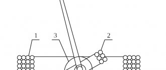
Based on the design, there are 2 types of current clamps: simple (a) - their operation is based on the operating principle of a single-turn transformer; complex (b) - they have a rectifier in their functionality, and their operation is also based on a single-turn transformer.
Device design
It is worth paying special attention to the picture diagram: it shows and marks the components of current clamps. So, number 1 on it directly indicates the wire that is being measured; number 2 - these are detachable cores (pincers); number 3 indicates the winding (secondary); number 4 is a built-in rectifier; number 5 is an image of a measuring frame; number 6 - drawing of the lacing resistance; number 7 indicates the toggle/mode switch; number 8 is the bracket (lever).
This diagram presented a very detailed internal structure of a clamp meter. However, it can be said that current clamps actually consist of three parts:
- Working: directly the clamps themselves and the magnetic circuit.
- Insulating: the space between the handle and the working part.
- Handle bodies.
You may be interested in: Features of a voltage comparator
Where is it used?
Thanks to the wide range of modifications of current clamps on the market and in stores, they have become a very popular power tool and are used everywhere - from the average home to a huge construction site.
There are two main types of electric clamps: for measuring alternating current and for measuring direct current. The former, in fact, are a universal tool and are excellent for taking readings on lines and with constant voltage.
So, consider the following situation: Galina and Ivan Petrov began to notice that their electricity bills were getting higher and higher every month. They began to figure out how this was possible and came to the conclusion that perhaps one of their neighbors had connected to their network and was stealing electricity. Ivan went to the store and bought current pliers. Then, having previously turned off all electrical appliances in the apartment, the Petrovs, using clamps, measured the current in a separate phase conductor and recorded a reading above zero. This means that their suspicion turned out to be correct. Now all that remains is to find the location of the unauthorized connection.
As an example, we can give one more situation. Ivan Petrov has a car. But here's the problem: the battery began to discharge very quickly. However, he did not install any additional devices such as a car radio. This means there is a leak somewhere.
Using electric clamps in a car
To do this, pliers wrap around the positive wire coming from the battery. After this, you need to sequentially begin to remove fuses and turn off all kinds of electrical consumers until the cause of the leak is found.
ICartool IC-M200A
This model measures AC current only. In addition, you can measure AC and DC voltage, resistance, and continuity.
Inside there is only the essentials - a device, probes, batteries and a description in Russian.
Designations on the body: compliance with European Union standards, double insulation, approval for category III work and voltage up to 600 volts. This means that with the help of this device you can repair everything that is connected to the input electrical panel in the building, but not this electrical panel itself. The plastic is of good quality, there are no sink marks or flash, the body does not creak and does not smell of anything.
The program wheel is designed to be rotated only from the side with your right thumb, while left-handed users will have to rotate it with their index finger. The selected operating mode can be determined by the arrow on the wheel.
On the reverse side we see the battery compartment cover, the manufacturer's quality control department sticker and a sticker indicating compliance with the customs union standards. Let's start by installing the batteries. The device comes with 2 AAA batteries, we will supply them.
The battery compartment cover is secured with one screw, which is screwed into a threaded bushing.
Probes. Length 85 cm. The ends are covered with caps.
Let's measure the resistance:
With a current of 2 A, the voltage drop on one probe is 0.76 V, on the other - 0.68 V. The resistance of the pair is 0.72 Ohm. This is a bit much. But let's not forget that the device measures current only with clamps; probes are used to measure voltage and resistance. For these tasks, the resistance of the probes is unimportant. But we must take into account that these probes are only for measuring voltage; you should not equip them with any other multimeter.
Screen.
Sufficient contrast, but viewing angles are not very good. When viewed from above, from the side of the jaws, the image disappears at some point. It looks like this:
There are also strengths - the screen has a pleasant bluish backlight
. And when certain current and voltage values are exceeded, it turns amber.
Unfortunately, the blue backlight automatically turns off after a few seconds of operation. The device itself also automatically turns off after a few minutes of inactivity. “Func” button pressed.
. You can make sure that the auto-shutdown function is disabled by the disappearance of the clock icon in the corner of the screen.
Opening.
The body is assembled on two self-tapping screws. The first is accessible from the battery compartment, the second is hidden under a sticker with the serial number. The battery contacts are connected to the board via springs. This simplifies disassembling the case - the half of the case does not hang on the wires. There is a double groove along the perimeter of the case, which makes it difficult for dust and moisture to get inside.
Soldering is not without its flaws. There are solder snot hanging out here and there. Some wires are not threaded into the holes of the board, but are stuck to the surface with a drop of solder.
The device controller is in a drop of compound. On the one hand, such a solution is considered non-repairable. But on the other hand, the economic effect of repairing a device in this price range is not obvious.
Noteworthy is the strange arrangement of thermistors at the input. The long, intricately curved legs of semiconductor devices are dangerously close to each other. At the same time, they carry full voltage, up to 600 volts! Judging by the silk-screen printing, the designers planned to install thermistors on different sides of the board (PTC2 is in the photo below).
But the collectors decided otherwise.
The flux has not been washed off in some places - pay attention to the soldering of wires at the bottom of the frame in the last photo.
So the impressions from the inside of the device are mixed. Well thought out. Implemented with a C grade. But it can be completed relatively easily with a soldering iron and alcohol.
DC voltage measurement.
Here we have one scale with a limit of 600 volts and a resolution of one decimal place. And the stated error is ±0.5% of the readings plus 5 least significant units. For ten volts this will be 0.5 V. But for tests we use the reference voltage source on the AD584LH chip with an accuracy 100 times higher - 0.005 V.
Testing 2.5 V.
It underestimates a little, but within the stated measurement error.
5V:
Likewise.
7.5V:
It looks like the small bug is permanent.
10.0 V:
For practical use, such accuracy is quite sufficient. It is unlikely that anyone will repair precision equipment using 200 ampere clamps.
Resistance measurement.
There are two ranges: up to 2 KOhm and up to 20 KOhm.
Due to the fact that the device does not have automatic range detection, measurements are carried out as quickly as possible. If you carefully examine the recording, 30 frames fit between touching the contacts and the appearance of readings on the screen.
At a frame rate of 60 per second, that's 0.5 seconds. The accuracy of the readings corresponds to the stated ones. Calling.
Speed is especially important here. Likewise, let’s look frame by frame:
Strange, but the delay in turning on the buzzer depends on the pause between measurements. The smaller it is, the smaller the delay.
If “cold”, then after 0.3 seconds the screen shows the resistance value, and only after a second the red LED lights up and the buzzer turns on. If the next measurement is taken immediately, then the readings, the buzzer, and the LED turn on simultaneously with a delay of 0.3 seconds. It's all a little confusing, of course.
How to use a clamp meter
If you want to measure and find out the value of electricity consumed in 220 V networks (in an apartment, house), you can calculate it using the formula:
P = A ⋅ V ⋅ cosφ
where, cosφ = 1
Example: You need to measure the power consumption load of your apartment, house or some electrical appliance. We set the range switch to position ACA 200. Open the pliers and grasp one wire from the spirit (preferably phase). After a moment, the device will show some value, for example, 8 A.
Using the formula, we calculate the power consumption:
P = 8 ⋅ 220 ⋅ 1 = 1760 W = 1.76 kW
Current clamp meters are convenient, specialized devices that allow you to quickly and easily measure current. Most devices have a button that is responsible for recording the result. This makes it easier to work in tight spaces where it is impossible to constantly monitor the device display.
How to measure current
Measuring current in a circuit is not difficult: by pressing the lever, you need to open the clamps and pass the wire to be measured through them, and then record the measurement that appears on the screen.
First of all, you need to remember safety precautions. It is important that during the measurement there is no short circuit and no person gets electrocuted. Of course, for this purpose, the pliers themselves are covered with an insulating sheath. Therefore, you should not be afraid of electric shock, but you should also not forget that the device must be completely dry.
It is discussed above what electrical clamps are intended for. These devices are used to measure, usually alternating current, as quickly and accurately as possible. Depending on the design, this simple device can also serve as a thermometer or be used as a voltage or frequency sensor. In good hands, this device can become a real and irreplaceable weapon.
Construction and tension
Depending on the voltage of the electrical networks in which current clamps are used for measurements, the design of these devices can be adapted accordingly. Thus, in electrical networks up to 1000 volts, electrical clamps are used with “jaws” controlled with one hand.
But in electrical networks up to 10,000 volts, two-handed current clamps are used. This is caused by the need to remove the hands at a safe distance (from 38 cm and more) from live parts that are under high voltage. Such “jaws” are no longer a multimeter, but simply an ammeter. Moreover, many models use an analog dial gauge. Working with clamp meters at high voltage is associated with an increased risk of electric shock.
Safety precautions when working
Interaction with any devices that come into contact with electricity requires compliance with certain safety measures. The mites in question are no exception. During active actions carried out by them, it is prohibited:
- when connecting them to live elements, touch the open connectors;
- when working under voltage, measure resistance;
- switch ranges when the conductor is in the instrument;
- exceed the maximum overload capacity of the tool for a certain range.
With professional tools in electrical installations with voltages above 1000 V, work is carried out by 2 workers: 1 with group III and 1 with group IV.