In radio engineering one often encounters inductive reactance. Its source is coils. They are a two-terminal network wound with enameled copper wire (usually PETV) on a ferrite or iron core. Similar parts are found in a wide range of equipment: from ancient Soviet radios to the latest PC motherboards.
Inductors
Types of resistance and their features
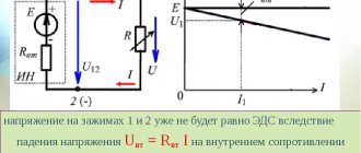
If there is a constant voltage in the circuit, then, knowing its resistance, you can find out the current strength using Ohm's law. It says that the strength of the current is proportional to the voltage that causes it. The proportionality factor represents normal resistance. It is usually called active.
If the voltage is constant, then the resistance will only be active. Its value determines how much energy of the electric field is converted into heat, that is, irretrievably lost. Therefore, when working with cables SIP-3 1×50, SIP-2 3×70 and others, you must remember that energy losses due to active resistance can be significant.
The use of alternating current is more common. It occurs under the influence of voltage that changes cyclically according to a sinusoidal law. Such a current generates reactance, which complements the action of the active one. There are two types of reactance of different nature - based on inductance or capacitance. Their distinctive feature is that they do not contribute to the waste of electricity, but to convert it into another form.
It must be taken into account that the use of various types of cables is associated not only with the presence of active resistance, but also reactive one. For example, cables SIP-3 1×50, SIP-2 3×70, AC-95 can be used in electrical networks with active, inductive, and capacitive resistance.
To understand what inductive reactance is, you can imagine a circuit in which there is a coil connected to an alternating current source. As you know, voltage changes according to a sinusoidal law. With these changes, the coil will create a magnetic field, which will, in particular, affect the current flowing through it. According to the nature of the magnetic field, when the current decreases, the magnetic field contributes to its increase, and when it increases, the opposite effect is observed. In addition, the AC circuit with active resistance wastes energy to generate heat.
In practice, we are talking about the action of inductive reactance, which provides a phase shift between current and voltage. The movement of charges creates a field, which in turn prevents the current from changing. Such resistance is present not only in coils, but also, for example, when using SIP-2 3x70 cable.
Capacitance has a different nature. To explain, consider a circuit consisting of an AC source and a capacitor. The latter is a part in which two surfaces are parallel to each other and do not have direct electrical contact.
When using direct current, charges accumulate on the plates of the capacitor: one is positive, and the other is negative. The electric field due to the accumulated charge is a source that counteracts the current. Therefore, a capacitor in a DC circuit has an infinitely large resistance. The current does not pass through the dielectric separating the capacitor plates.
In an alternating current circuit, a capacitor is cyclically charged and discharged, ensuring the movement of electrical charges. This process in an alternating current circuit with active and reactive resistance will occur with a delay relative to the sinusoidal voltage change. Thus, the capacitor represents a finite resistance, called capacitive.
The difference between capacitive and inductive reactance is that direct current flows through an inductive coil, but cannot pass through a capacitor. However, alternating current can flow in both circuits without any problem.
What are the differences?
The difference between these types of electrical resistance is that energy does not accumulate “inside” the activity type, since it enters the active element and is given to the environment in the form of another type. This could be heat or mechanical lifting of a load, a glow, a chemical reaction, or giving something speed.
Inductive quantity and its formulas
Important! The energy supplied to an electrical element with active electrical resistance is transformed and converted, but is not returned to the network. Reactive resistance, on the contrary, accumulates energy within itself for ¼ of the entire period of sinusoidal electric current, and over the next quarter returns it back to the network
That is, the energy received is not transferred to the environment
Reactive resistance, on the contrary, accumulates energy within itself for ¼ of the entire period of the sinusoidal electric current, and over the next quarter returns it back to the network. That is, the energy received is not transferred to the environment.
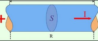
Complex resistance of an individual electrical element of the network R
In the activity type, the phases of electric currents and voltages coincide, therefore, a certain amount of electricity is released. In reactive form, the phases of electric current and voltage diverge, so energy is transferred back. This largely explains why active electrical elements heat up, while reactive elements do not.
Active resistance in an alternating sinusoidal current circuit
What is called inductive reactance
When an alternating voltage is applied to a coil, the current passing through it changes according to the applied voltage. This causes a change in the magnetic field, creating an electromotive force that interferes with what is happening.
Measuring circuit
In such a circuit there is a dependence of electrical parameters on two types: conventional and inductive. They are designated, respectively, as R and XL.
On a normal one, power is released. However, on reactive elements it is zero. This is due to the constant change in direction of the alternating current.
During one oscillation period, energy is pumped into the coil twice and returned to the source the same number of times.
Definition of inductance
Coil equivalent circuit with series connection of elements
In a circuit with a series connection of elements, a real coil is characterized by active resistance R and inductance L.
Active resistance is determined by the amount of power loss
R = P/I2
and inductance is determined by the design of the coil. Let us assume that the current in the coil (Fig. 13.9, a) is expressed by the equation i = Imsinωt. It is necessary to determine the voltage in the circuit and power. With alternating current, an e occurs in the coil. d.s. self-induction eL therefore the current depends on the action of the applied voltage and emf eL. The equation of electrical equilibrium of the circuit, compiled according to Kirchhoff’s second law, has the form:
The voltage applied to the coil consists of two terms, one of which uR is equal to the voltage drop in the active resistance, and the other uL balances the self-induction emf.
In accordance with this, the coil in the equivalent circuit can be represented by active and inductive resistances connected in series (Fig. 13.9, b). Additionally, note that both terms on the right side of equality (13.12) are sinusoidal functions of time. According to the conclusions obtained in these previous two (first, second) articles, we get that uR is in phase with the current, UL is ahead of the current by 90°.
That's why:
u = R*Imsinωt + ωLImsin(ωt+π/2).
The principle of operation of inductive reactance of lines
It is inductance that is recognized as the main characteristic for coils, along with a similar indicator for their windings. R of the reactive type, manifested under the influence of self-induction EMF, grows in direct proportion to the frequency of the current.
The reactive and active components determine the total resistance, which can be represented as the sum of the squares of each indicator.
Special tables will help you quickly cope with the task of calculating nominal indicators. They contain all the main characteristics for the most common conductors. But in practice, it is often necessary to find out X for a section with a specific length. In this case, the main tool is the already given expression
Design and varieties
All types of inductors have the same design, regardless of their application. The features introduced to obtain individual parameters affect the type of part.
- Solenoid. Component with increased overall length of winding wire. The winding is larger than the diameter of the part.
- Toroidal. In such a coil, the solenoid is made in the shape of a “torus”.
- Multilayer type, has several rows of winding.
- Sectioned. The winding has several divided sections, sometimes made of wire of different sections. The best known coil of this type is the transformer or choke.
- Universal, can combine several winding options at once.
Regardless of design, all coils operate on the same principle.
What factors does resistance depend on?
Changing the current creates an electromagnetic field of variable intensity. The result of its effect on the conductor is to counteract the current change that occurs.
This opposition is called reactance. There are two types of it: inductive and capacitive. The first is created when there is an inductive element in the circuit, the second - a capacitor.
In a situation where a coil is present in the circuit, its response increases as the frequency increases.
Circuit in which induction occurs
When its inductance decreases, the opposing force also becomes less. As it increases, it increases.
Inductive reactance is significantly related to the shape the conductor takes. It is also present on a separate wire lying straight. However, if there is another one nearby, it will have an additional effect, which will affect the value under consideration.
The characteristic of an individual wire under consideration can be determined depending on its thickness, but it is in no way related to its cross-section.
The principle of operation of electromotive force
Capacitive conductivity of lines
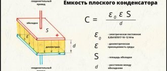
Electric lines, in addition to active and inductive resistance, are also characterized by capacitive conductivity, which is due to the capacitance between the wires and between the wires and the ground.
The value of the working capacitance in a three-phase overhead line can be approximately determined by the formula:
From this formula it is clear that the working capacity will increase with an increase in the cross-section of the wires and a decrease in the distance between them. Therefore, with equal cross-sections of current-carrying parts, low-voltage lines have a greater working capacity than high-voltage lines. Due to the small distances between the current-carrying conductors of the cable and the greater dielectric constant of the insulation compared to air, the working capacity of the cable line is significantly greater than the capacity of the overhead line.
The capacitive conductivity of a single-circuit overhead line is determined by the formula:
Determining the working capacitance of a cable line using formulas that include the dielectric constant of the cable insulation, geometric dimensions and other design features is not an easy task, therefore the values of the working capacitance are determined using special tables compiled by the manufacturer for various brands of cables, depending on their nominal voltage.
The capacitive current at the beginning of the line at idle (with electrical receivers turned off) can be determined from the formula:
Where: U – line voltage of the network, V; l – line length, km;
Capacitive currents are of serious importance in overhead lines with operating voltages of 110 kV and above and in cable lines with voltages above 10 kV. When calculating electrical networks with voltages lower than those listed above, the line capacitance may not be taken into account. The capacitance of the conductive parts of the line in relation to the ground is important when calculating grounding devices and protection.
In a network with an isolated neutral, the magnitude of the capacitive current of a single-phase ground fault can be approximately determined by the formulas:
For overhead line:
For cable line:
Inductor
It consists of an insulated wire wound repeatedly around a core.
Typically the frame has a cylindrical or toroidal shape.
Inductance is considered as the main characteristic of the coil. This quality expresses the ability of an element to convert alternating current into a magnetic field.
Important! Magnetic properties exist even in a single wire, provided that the current passing through it changes. The influence of the field is directed so as to counteract its change. If it increases, the field will slow it down, and if it weakens, it will strengthen it.
Inductors
Determining the direction of the field lines obeys the “rule of thumb”: if the hand clenched into a fist has the thumb pointing in the direction of the change in current strength, then the closed fingers indicate the direction of the field lines.
Thus, if the wire is repeatedly wound on a cylindrical base, then the power lines from different turns add up and pass through the axis.
It will be interesting➡ Instrumentation. Types and scope
In order to increase the inductance many times over, a core of ferromagnetic material is placed in the center of the cylinder.
Solenoid
This concept refers to a cylindrical winding of wire, which can be wound in one or several layers. The length of the cylinder is significantly greater than the diameter. Due to this feature, when an electric current is supplied, a magnetic field is generated in the cavity of the solenoid. The rate of change of magnetic flux is proportional to the change in current. The solenoid inductance in this case is calculated as follows:
df : dt = L dl : dt.
This type of coil is also called an electromechanical actuator with a retractable core. In this case, the solenoid is supplied with an external ferromagnetic magnetic circuit - a yoke.
- The first is capable of controlling line pressure.
- The second model differs from others in the forced control of clutch locking in torque converters.
- The third model contains pressure regulators responsible for the operation of gear shifting.
- The fourth is controlled hydraulically or by valves.
Formulas, dependencies and types of inductance
Electrical inductance L is a quantity equal to the proportionality coefficient between the current I flowing in a closed circuit and the magnetic flux it creates, otherwise called the flux linkage Y:
Y = LI.
If voltage is applied to the coil terminals for some time, current I will begin to flow in it and a magnetic field will form. The lower the inductance L, the faster this process occurs. As a result, the two-terminal network under consideration will accumulate a certain amount of potential energy. When the power is turned off, it will try to return it. As a result, a self-inductive emf E is formed at the coil terminals, which is many times higher than the initially applied voltage. A similar technology was previously used in magnetos of internal combustion engine ignition systems, and is now widely found in boost DC-DC converters.
Formula for self-induction EMF, here t is the time during which the current I decreases to zero. Simple DC-DC boost converter
A coil (also known as a choke) is a radio component with pronounced inductance, because that’s exactly what it was created for. However, in principle all elements have this property. For example, a capacitor, a resistor, a cable, just a piece of wire, and even the human body also has some inductance. In the calculations of RF circuits, this must be taken into account.
Important! When measuring inductance with a specialized device, it is worth remembering that you cannot hold both of its terminals with your hands. Otherwise, the readings may change and be incorrect. This is caused by the inclusion of the human body with its own inductance in the measured circuit.
Relationship between phases U and I on XL
Since the active resistance of the coil is equal to zero (purely inductive resistance), then all the voltage applied by the generator to the coil is used to overcome the e. d.s. self-inductance of the coil. This means that the graph of the voltage applied by the generator to the coil is equal in amplitude to the graph of e. d.s. self-induction of the coil and is in antiphase with it.
The voltage applied by the generator to the purely inductive reactance and the current flowing from the generator through the purely inductive reactance are shifted in phase by 90 0, i.e. that is, the voltage leads the current by 90 0.
In addition to inductive reactance, a real coil also has active resistance. These resistances should be considered connected in series.
At the active resistance of the coil, the voltage applied by the generator and the current coming from the generator are in phase.
On a purely inductive reactance, the voltage applied by the generator and the current coming from the generator are shifted in phase by 90 0. Voltage leads current by 90 0. The resulting voltage applied by the generator to the coil is determined by the parallelogram rule.
click on the picture to enlarge
The resulting voltage applied by the generator to the coil always leads the current by an angle less than 90 0.
The magnitude of the angle φ depends on the values of the active and inductive resistance of the coil.
About the resulting coil resistance
The resulting resistance of the coil cannot be found by summing the values of its active and reactive resistances
.
The resulting coil resistance Z is
Inductor in an AC circuit
An inductor in an AC circuit behaves differently than a resistor. If resistors simply resist the flow of electrons (the voltage across them is directly proportional to the current), then inductors resist the change in current passing through them (the voltage across them is directly proportional to the rate of change of current). According to Lenz's Law, the induced voltage always has a polarity that attempts to maintain the current value of the current. That is, if the current increases, the induced voltage will “slow down” the flow of electrons; if the current decreases, the voltage polarity will reverse and will “help” the electron flow remain at the same level. This resistance to a change in current is called reactance.
The mathematical relationship between the voltage across an inductor and the rate of change of current through it is as follows:
The ratio di/dt is the rate of change of instantaneous current (i) over time, and is measured in amperes per second. Inductance (L) is measured in Henry, and instantaneous voltage (u) is measured in volts. To show what happens with alternating current, let's analyze a simple inductive circuit:
A simple inductive circuit: the coil current lags the voltage by 90 o.
If we plot the current and voltage for this simple circuit, it will look something like this:
As you remember, a change in voltage across an inductor is a response to a change in the current passing through it. From this we can conclude that the instantaneous voltage is zero whenever the instantaneous value of the current is at its peak (zero change, or zero slope of the current sine wave), and the instantaneous voltage is equal to its peak value whenever the instantaneous current is at the points of maximum change (points of steepest slope of the current wave at which it crosses the zero line). All this leads to the fact that the voltage wave is 90 o out of phase with the current wave. The graph shows how the voltage wave gives a “head start” to the current wave: voltage “leads” the current, and the current “lags” behind the voltage.
Read also: How to make light music on a speaker
If we plot the power values of our circuit on this graph, then everything will become even more interesting:
Since instantaneous power is the product of instantaneous voltage and instantaneous current (p = iu), it will be zero if the instantaneous voltage or current is zero. Whenever the instantaneous current and voltage values are positive (above the zero line), the power will also be positive. Similar to the example with a resistive circuit, the power will take a positive value even if the instantaneous current and voltage have negative values (below the zero line). However, due to the fact that the voltage and current waves are 90 o out of phase, there are cases when the current is positive and the voltage is negative (or vice versa), resulting in negative instantaneous power values.
But what is negative power? Negative power means that the inductor is releasing energy back into the circuit. Positive power means that the inductor absorbs energy from the circuit. Since positive and negative power cycles are equal in magnitude and duration, over the course of a complete cycle, the inductor puts back into the circuit as much power as it draws from it. In practical terms, this means that the reactance of a coil does not dissipate any energy, which is different from the reactance of a resistor, which dissipates energy as heat. However, all of the above is true only for ideal inductors, the wires of which have no resistance.
The resistance of the inductor, which changes the strength of the current, is interpreted as the resistance to the alternating current as a whole, which, by definition, constantly changes instantaneous magnitude and direction. This AC resistance is similar to normal resistance, but differs from it in that it always results in a phase shift between current and voltage, and also dissipates zero power. Due to these differences, this resistance has a slightly different name - reactance. Reactance, like regular reactance, is measured in Ohms, only it is denoted by the symbol X, not R. To be more specific, the reactance of an inductor is usually denoted by the capital letter X with the letter L as an index: XL.
Since the voltage across the inductor is proportional to the rate of change of current, it will be greater for rapidly changing currents and less for slower changing currents. This means that the reactance of any inductor (in Ohms) is directly proportional to the frequency of the alternating current. The exact formula for calculating reactance is as follows:
If a coil with an inductance of 10 mH is exposed to frequencies of 60, 120 and 2500 Hz, then its reactance will take the following values:
In the reactance equation, the expression “2πf” is important. It means the number in radians per second that characterizes the "rotation" of alternating current (one complete cycle of alternating current represents one complete rotation). A radian is a unit of measurement for angles: there are 2π radians in one full circle, just as there are 360 o in one. If the alternator is two-pole, then it will produce one complete cycle for each complete revolution of the shaft, which will mean 2π radians or 360 o. If the constant 2π is multiplied by the frequency in hertz (cycles per second), the result is a number in radians per second known as the angular (cyclic) frequency of the alternating current.
In addition to the expression 2πf, the angular frequency of alternating current can be denoted by the lowercase Greek letter ω (Omega). In this case, the formula XL = 2πfL can be written as XL = ωL.
It is important to understand that the angular frequency is an expression of how quickly the wave completes its cycle, which is equal to 2π radians. It does not necessarily represent the actual shaft speed of the generator producing the alternating current. If the generator has more than two poles, its angular frequency will be a multiple of the shaft speed. For this reason, ω is sometimes expressed in units of electrical radians per second to distinguish it from mechanical motion.
With any method of expressing the angular frequency, it is obvious that it is directly proportional to the reactance of the inductor. As the frequency of the alternating current (or the rotation speed of the generator shaft) increases, the inductor will provide greater resistance to the passage of current and vice versa. The alternating current in a simple inductive circuit is equal to the voltage (in Volts) divided by the reactance of the inductor (in Ohms). As you can see, this is similar to the fact that AC or DC current in a simple resistive circuit is equal to the voltage (in Volts) divided by the resistance (in Ohms). As an example, let's consider the following diagram:
However, we must keep in mind that voltage and current have different phases. As mentioned earlier, voltage has a phase shift of +90 o with respect to current (figure below). If we represent the phase angles of voltage and current mathematically (in the form of complex numbers), we will see that the inductor's resistance to alternating current has the following phase angle:
The current across the inductor lags the voltage by 90 o.
Mathematically, we can say that the phase angle of the inductor's resistance to alternating current is 90 o. The phase angle of current reactance is very important in circuit analysis. This importance is especially evident when analyzing complex alternating current circuits, where reactive and simple resistances interact with each other. It will also prove useful for representing the resistance of any component to electrical current in terms of complex numbers (rather than scalar quantities of resistance and reactance).
Calculation of the inductive reactance of the coil
Any inductance, incl. coil provides some resistance to alternating current. How to calculate it was described above. From the formula XL=2pfL it is clear that the resistance of the inductor primarily depends on the frequency of the current flowing through it and its inductance. Moreover, the relationship with both parameters is directly proportional.
Impedance
Frequency is a characteristic of the external environment; the inductance of the coil depends on a number of its geometric properties:
L=u0urN2S/l,
Where:
- u0 – magnetic permeability of vacuum – 4p*10-7 H/m;
- ur – relative permeability of the core;
- N – number of throttle turns;
- S – its cross section in m2;
- l is the length of the coil in meters.
Having the above-described formulas and information about the material and dimensions of the coil, you can fairly accurately estimate its inductive reactance without any measuring instruments.
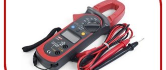
Additional Information. Some digital multimeters have an inductance mode. This feature is rare, but sometimes it turns out to be very useful. Therefore, when choosing a device, you should pay attention to whether it is capable of measuring inductance.
What parameters does the coil have?
Its design depends on where the inductive element will be used and at what frequency it will operate. There are general parameters:
- L – inductance;
- R sweat – loss resistance;
- Q – quality factor;
- its resonance and parasitic capacitance;
- coefficients TKI and TKD.
Inductance (self-inductance coefficient) L is the main electrical characteristic of the element, which shows the amount of energy accumulated by the inductor when current flows. The greater the inductance, the higher the energy in the coil. Unit of measurement L – 1 Hn.
When current and magnetic field interact in the winding, harmful phenomena occur. They contribute to the occurrence of losses, which are denoted by R sweat. The loss formula looks like:
R sweat = rω + rd + rs + re.
The terms of the formula are losses:
- rω – in wires;
- rd – in dielectric;
- rs – in the core;
- re – for eddy currents.
As a result of such losses, the impedance of an inductive two-terminal network cannot be called entirely reactive.
The quality factor of a two-terminal network is determined by the formula:
Q = ω*L/R sweat,
where ω*L = 2π*L – reactance.
When winding the turns of an element, unnecessary capacity appears between them. Because of this, the choke turns into an oscillatory circuit with its own resonance.
TCI is an indicator describing the dependence of L on Т0С.
TKD is an indicator that describes the dependence of the quality factor on T0C.
Information. Changes in the main parameters of an inductive two-terminal network depend on the TCI, TKD coefficients, as well as on time and humidity.
Inductance in a DC circuit
To better understand the processes occurring in the coil, let’s consider what happens in the coil when a constant voltage is applied to it.
When a power source is connected to the coil, a current begins to flow in it, which creates a magnetic field around it. Magnetic field lines propagate through the turns of the coil outward, crossing them, and thus form a self-induction emf. This EMF, according to Lenz's rule, will prevent an instantaneous increase in current in the coil. The current increases gradually, according to an exponential law. After a short period of time, the transient process ends and the current reaches its normal value. The duration of the current rise in seconds is determined by the formula:
t=3L/R,
where L is the inductance of the coil in henry, and R is the total resistance of the entire circuit in ohms. If, for example, the inductance of the coil is L=0.6 G, and the resistance of the circuit is R=60 Ohm, then the duration of the transient process will be equal to: t=3•0.6/60=0.03 sec.
It will be interesting➡ Twisted pair: categories, crimping, work tips
When the battery is disconnected from the inductance coil, a transient process also occurs (such an experiment with the primary winding of a transformer is shown on the “Electromagnetism” page, Fig. e). In this case, the magnetic lines of force will approach the center of the coil, again crossing its turns. A self-induction emf is created, which is no longer directed against the current, but (again according to Lenz’s rule) coinciding with the direction of the interrupted current.
If the coil has a large inductance (in our experience the coil is the primary winding of a transformer with a large number of turns and a significant iron core) and a large current flows through it, then the self-inductive emf appearing at the ends of the inductor can reach a value many times greater than the source voltage nutrition. This is explained by the fact that when the supply network is opened, the energy stored in the magnetic field of the coil does not disappear, but turns into current. The voltage between the ends of the inductor can reach such values that can lead to a breakdown between the windings, as well as failure of semiconductor devices. This must be taken into account in practice when working with devices that have coils with high inductance through which significant current passes.
How to measure at home
Instruments for directly measuring inductance are expensive and are rarely used at home. Results can be obtained with acceptable accuracy using conventional instruments for measuring alternating current: an ammeter and a voltmeter. An ohmmeter is also needed.
The procedure is as follows:
- Using an ohmmeter, determine the active resistance of the winding R.
- Connect the transformer in series with the ammeter to the network.
- A voltmeter is connected parallel to the winding.
- According to the instrument readings, the impedance of the transformer is determined: Z=U/I
- Inductive reactance is found by subtracting active resistance from impedance: XL=ZR
- Inductance is determined by the formula: L=XL/(2πf), where π is pi 3.14, f is the measurement frequency.
As a rule, the active resistance of the winding is significantly (several orders of magnitude) less than the inductive one, so it can be ignored. This is why connecting a transformer to a DC voltage circuit causes a short circuit. The winding current will be limited only by the active resistance.
Inductance in AC circuit
For experiments with direct current, the inductor is wound with a thin wire with a large number of turns. This is done so that when voltage is applied to it from a powerful power source, the turns of the coil do not burn out, because when winding turns with a thick wire, the resistance will be small, and the current through it will be large (according to Ohm’s law for direct current I=U/R) and it can burn out. The inductor's resistance to direct current (which can be measured with a multimeter) is called active resistance.
It will be different if alternating current is supplied to the coil circuit. In this case, the magnetic field of the inductor also becomes variable. The figure shows how the magnetic field changes with a sinusoidal current. During the period, the magnetic field changes both its strength and its direction according to a sinusoidal law. This means that in this case a self-induction EMF arises, which, according to Lenz’s rule, will interfere with the externally applied voltage.
Let's consider a graph of the processes occurring in the inductor. When the coil is connected to an alternating current circuit in the first quarter of the period (0º-90º), an increasing voltage is applied to the coil and its magnetic field “expands”, accumulating magnetic energy. The current, at this moment, counteracting the EMF of self-induction, is maximum and opposite in sign to the voltage on the coil. During the other quarter of the period (90º-180º), when the voltage across the inductor decreases, the magnetic field “collapses”, inducing a self-inductive emf, which coincides with the direction of the current. This self-induction current in the coil is already trying to “help” the decreasing alternating current to maintain the achieved high magnetic flux. During this half-cycle, the inductor no longer consumes, but gives energy back to the generator. Consequently, there is a constant exchange of energy between the generator and the coil. This means that the average power consumption of the coil is zero. Due to the 90º phase difference between current and voltage, the inductor has reactive power and, accordingly, reactance, like a capacitor. The only difference is that in an inductor the voltage leads the current, and in a capacitor it is the other way around. The reactive (inductive) resistance of the coil, unlike its active resistance, does not cause irreversible energy losses.
Let's say we take an ideal coil in which wire resistance and other losses are not taken into account. Then the inductor will provide an inductive resistance XL to the alternating voltage, which is measured in ohms and calculated by the formula:
where f is the frequency of the current in hertz (Hz), and L is the inductance of the coil in henry (H). This shows that the magnitude of the inductive reactance of the coil depends on the frequency and inductance. The higher the frequency of the current and the greater the inductance of the coil, the greater the inductive reactance.
For example, let’s find the inductive reactance of a coil with an inductance of 5G at a frequency of 50Hz. XL=2π•50•5=1570 Ohm. At a frequency of 1 kHz, this coil will have an inductive reactance of 31 kOhm, and at 1 MHz - 31 MOhm. The graph shows the dependence of the mentioned coil on frequency.
Now, knowing the value of inductive reactance, we can write Ohm’s law with alternating current through the coil:
For example, let's find the current that flows through an ideal coil with inductance L = 500 μH, if it is connected to an alternating voltage U = 0.4 V and frequency f = 500 kHz. I= 0.4/2•3.14•5•103•500•10-6=0.25 mA
In a real coil, it is necessary to take into account not only the inductive reactance, but also the loss resistance Rpot. At low frequencies, Rpot is equal only to the coil wire resistance. As the frequency on the coil increases, the loss resistance will increase due to the appearance of other losses (eddy currents, surface effect of the conductor, etc.) (Fig.a). Therefore, the total resistance of the inductor to alternating current at medium frequencies is equal to: and is called impedance. At high frequencies, the own (parasitic) capacitance of the Sparaz coil, which shunts the inductance, also begins to have an effect (Fig.b).
The main parameters of high-frequency inductors are inductance, quality factor and self-capacitance. Inductance depends on the number of turns, the size of the coil and the presence of a ferromagnetic core. The more turns wound on a coil, the greater its inductance. And the presence of a core will increase the inductance of the coil. The quality factor determines the quality of the inductor and is equal to the ratio of the inductive resistance to the loss resistance: The higher the quality factor, the better the quality of the coil. A good quality coil is considered to be a coil with a quality factor of 50 to 200. To achieve this quality, the following means are used: – the use of cores, which increase the inductance with a smaller number of turns of the coil (i.e., the wire resistance decreases); – increasing the thickness of the wire, which, however, will increase the dimensions of the coil; – in the range of long and medium waves, the use of Litz wire, which consists of a certain number of wires insulated from each other. The inductor's own capacitance is due to the winding capacitance and is undesirable. To reduce it, various methods of coil winding are used. One of the methods is cross-winding of the “station wagon” type (Fig. c). The winding of turns is also used not tightly to each other, but at a certain distance with a forced step (Fig. d, e).
Calculation of equivalent resistance of circuit elements
The determination of the total circuit resistance will depend on what type of configuration the circuit components are made of. For parallel and serial connections, the calculation rules will be different. When making calculations, you need to rely on Ohm's law.
According to it, all series-connected parts connected to an alternating current circuit will have the same electric current value:
I=U/Z, where Z is the total impedance of the circuit.
The voltages will differ and will be tied to the resistance of the parts: at the ends of the resistor its value will be equal to UR = IR (here R is the active resistivity of the element), for the inductor - UL = IXL, for the capacitive element - UC = IXC (XL and XC are reactive indicators corresponding devices). Since the voltage vectors of the coil and capacitor have opposite directions, the total indicator on the reactive parts will be equal to: UX = UL – UC. The reaction will be equal to: X = XL – XC.
Voltages (total, reactive and active) can be represented as a right triangle. From this it turns out that U² = UR² + UX². Since the counteractions of the components included in the circuit are proportional to the voltages, we have Z2=R2+X2=R2+(XL – XC)2.
For a parallel connection, it is customary to derive impedance values from the conductivities of the elements, which are the inverse of their resistances. Hence 1/z2 = 1/R2 + 1/X2. Thus, the following formula comes out:
Z2=1/(1/R2+(1/ XL – 1/ XC)2).
The total resistance is determined by the component composition of the circuit and the nature of the connection of its elements. When calculating indicators, Ohm's law is used.
Cable insulation resistance
To find R cable insulation, you need to proceed from its type. There are the following varieties:
- 1000 V and more - high voltage.
- Below 1000 V - low voltage.
- Control electrical cables - protective circuits, secondary circuits of switchgear (indicative relays), power circuits of electric drives, and so on.
To measure R insulation, a specialized device is required. High-voltage and low-voltage are determined at a voltage of 2500 V, when control ones are from 500 to 2500 V. If a high-voltage one with a value greater than 1000 V is used, then its insulation R must be at least 10 MOhm. If a low-voltage one with a value of less than 1000 V is used, then its insulation R must be at least 0.5 Mohm. Control cables must have insulation R of at least 1 MOhm.
