Main parameter of the transformer
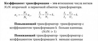
The main characteristic of any transformer is the transformation ratio. It is defined as the ratio of the number of turns in the primary winding to the number of turns in the secondary winding. In addition, this value can be calculated by dividing the corresponding EMF indicators in the windings.
Formula
In the presence of ideal conditions, when there are no electrical losses, the solution to the question of how to determine the coefficient is carried out using the ratio of the voltages at the terminals of each winding. If the transformer has more than two windings, this value is calculated for each winding in turn.
In step-down transformers, the transformation ratio will be above unity; in step-up devices, this indicator ranges from 0 to 1. In fact, this indicator determines how many times the voltage transformer reduces the supplied voltage. It can be used to determine the correct number of turns. This coefficient is determined on all available phases and on each branch of the network. The data obtained is used for calculations, making it possible to identify wire breaks in the windings and determine the polarity of each of them.
You can determine the real transformation ratio of the transformer current using two voltmeters. In transformers with three windings, measurements are made on at least two pairs of windings with the lowest short-circuit current. If some elements of the transformer and branches are covered with a casing, then determining the coefficient becomes possible only for the terminals of the windings brought out.
In single-phase transformers, to calculate the operating transformation ratio, a special formula is used in which the voltage supplied to the primary circuit is divided by the simultaneously measured voltage in the secondary circuit. To do this, you need to know in advance how each indicator is measured.
It is prohibited to connect voltage to the windings significantly higher or lower than the rated value specified in the transformer passport. This will lead to an increase in measurement errors due to losses of current consumed by the measuring device to which the three-phase transformer is connected. In addition, the measurement accuracy is affected by the no-load current. For most devices, a special table has been developed, which contains fairly accurate data that can be used in calculations.
Measurements should be carried out with voltmeters with an accuracy class of 0.2-0.5. A simpler and faster determination of the coefficient is possible with the help of special universal devices that make it possible to do without the use of extraneous AC voltage sources.
What is transformation ratio
The transformer does not change one parameter to another, but works with their values. However, it is called a converter. Depending on the connection of the primary winding to the power source, the purpose of the device changes.
These devices are widely used in everyday life. Their goal is to supply a home device with power that corresponds to the nominal value specified in the passport of this device. For example, the network voltage is 220 volts, the phone battery is charged from a 6 volt power source. Therefore, it is necessary to reduce the mains voltage by 220:6 = 36.7 times, this indicator is called the transformation ratio.
To accurately calculate this indicator, you need to remember the design of the transformer itself. Any such device has a core made of a special alloy and at least 2 coils:
- primary;
- secondary.
The primary coil is connected to the power source, the secondary coil is connected to the load, there can be 1 or more of them. A winding is a coil consisting of an electrical insulating wire wound on a frame, or without it. A complete turn of the wire is called a turn. The first and second coils are installed on the core, with its help energy is transferred between the windings.
For power transformer
Transformers can be step-up and step-down, to determine this you need to find out the transformation ratio , with its help you can find out which transformer. If the coefficient is less than 1, then the transformer is step-up (this can also be determined by the values; if there is more in the secondary winding than in the primary, then it is step-up), and vice versa, if K>1, then it is step-down (if there are fewer turns in the primary winding than in the secondary).
Formula for calculating the transformation ratio
Where:
- U1 and U2 - voltage in the primary and secondary windings,
- N1 and N2 - number of turns in the primary and secondary windings,
- I1 and I2 - current in the primary and secondary windings.
Current transformer
Formula for calculating the CT transformation ratio:
The coefficient values are usually very large compared to a power transformer. The values can be as presented in the table:
Let's determine the coefficient. transformations: let's take a CT with the values that are highlighted in the table 600/5 = 120. You can also take any transformer 750/5 = 150; 800/2 = 400, etc.
Voltage transformer
Formula for calculating the VT transformation ratio:
Let's calculate the transformation ratio for the VT shown in the photo below:
You need to take the voltage of the primary winding (red arrow) and divide it by the voltage of the secondary winding (yellow arrow). 35000/100 = 350.
Electric meter transformation ratio
The value of the transformation ratio is widely used for electricity metering devices. This data is necessary for the correct selection of an electric meter and further calculations of real energy consumption. For this purpose, an additional indicator is used - the calculated accounting coefficient.
In order to determine this value, readings are taken from the electricity meter and multiplied by the transformation ratio of the connected transformer device. For example, when solving the problem of how to find the desired indicator, 60 kW/h needs to be multiplied by a coefficient equal to 20 (30, 40 or 60). The result of multiplication is 60 x 20 = 1200 kW/h. The resulting value will be the actual energy consumption.
There are different types of metering devices. According to their principle of operation, they can be single- or three-phase. They are not connected directly; a current transformer must be connected between them in the circuit. Some meter designs suggest the possibility of direct connection. In networks with voltages up to 380 volts, 5-20 ampere meters are used. The meter receives electricity in its pure form, with a constant value.
Currently, induction meters are used, which are gradually being replaced by electronic models. They are considered obsolete because they cannot account for consumed electricity at different tariffs. In addition, they cannot transmit data over a remote distance. Therefore, they are being replaced by electronic meters capable of directly converting the incoming current into certain signals. These designs have no rotating parts, which significantly increases their reliability and durability. The transformation ratio of the meters has a direct impact on the accuracy of the received data.
CT classification
Classification of current transformers depending on the purpose of the device implies division into two categories.
- To ensure the operation of protective devices in variable networks.
- For connecting electricity meters.
Further classification is made according to the types of connection of the device to the network:
- for outdoor use;
- for indoor work;
- bus connection (without terminals for connecting primary current wires);
- external connection (primary current is connected to terminals with the corresponding designation);
- portable.
Transformer markings contain the necessary information about the device. It states:
- TT type;
- name or logo (symbol) of the manufacturer;
- instrument accuracy class;
- nominal (value of the primary and secondary parameter);
- power;
- year of issue.
The figure shows the decoding of the TT type.
Types of transformers depending on the insulation used:
- with a body made of bakelite, porcelain or filled with epoxy compound;
- with paper-oil (cardboard-oil) insulation;
- gas-filled.
How to calculate the transformation ratio
The transformation coefficient “k” is the ratio of the voltage U1 at the ends of the primary winding of the transformer to the voltage U2 at the terminals of its secondary winding, determined at no-load (when there are several secondary windings, then there are also several coefficients k, they are determined in this case one by one). This ratio is taken to be equal to the ratio of the numbers of turns in the corresponding windings.
The value of the transformation ratio is easily calculated by dividing the EMF of the windings of the transformer under study: EMF of the primary winding by EMF of the secondary.
The transformation ratio is very important as the value by which the secondary winding is brought to the primary. In operating conditions, the voltage transformation ratio, which is understood as the ratio of the rated voltages of the transformer, is of great importance.
For single-phase transformers there is no difference between the transformation coefficients of EMF and voltage, but in three-phase transformers they should be strictly distinguished from each other.
Ideally, there are no power losses (due to Foucault currents and heating of the winding conductors) in the transformer, therefore the transformation ratio for ideal conditions is calculated by simply dividing the voltages at the winding terminals. But nothing is perfect in the world, so sometimes it is necessary to resort to measurements.
In reality, we are always dealing with a step-up or step-down transformer. Voltage transformers that increase the transformation ratio are always less than one (and more than zero), while voltage transformers that increase the transformation ratio are always less than one. That is, the transformation ratio indicates how many times the current of the secondary winding under load differs from the current of the primary winding, or how many times the voltage of the secondary winding is less than that supplied to the primary winding.
For example, the TP-112-1 step-down transformer has a transformation ratio of 7.9/220 = 0.036 according to its passport, which means that the rated current (according to the passport) of the secondary winding of 1.2 amperes corresponds to a primary winding current of 43 mA.
Knowing the transformation ratio, measuring it, for example, with two voltmeters at idle, you can verify the correct ratio of the number of turns in the windings. If there are several clamps, then measurements are carried out on each branch. Measurements of this kind help to detect damaged windings and determine their polarities.
There are several ways to determine the transformation ratio:
a way to directly measure voltages with voltmeters;
AC bridge method (for example, a portable device of the “coefficient” type for analyzing the parameters of three-phase and single-phase transformers);
according to the passport of this transformer.
To find the real transformation ratio, two voltmeters are traditionally used. The nominal transformation ratio is calculated by dividing the voltage values measured at no-load (they are indicated in the passport for the transformer).
If a three-phase transformer is being tested, then measurements should be carried out for two pairs of windings with the lowest short-circuit current. When the transformer has terminals, some of which are hidden under the casing, the value of the transformation ratio is determined only for those ends that are accessible from the outside for connecting devices.
If the transformer is single-phase, then the operating transformation ratio can be easily calculated by dividing the voltage applied to the primary winding by the voltage on the secondary winding measured by a voltmeter at the same moment (with a load connected to the secondary circuit).
In relation to three-phase transformers, this operation can be performed in various ways. The first way is to supply a three-phase voltage from a three-phase network to the high-voltage winding, or the second way is to supply a single-phase voltage to only one of the three high-voltage windings, without output or with the zero point output. In each option, linear voltages are measured at the same terminals of the primary and secondary windings.
In each case, it is impossible to apply a voltage to the windings significantly exceeding the nominal value specified in the passport, because then the measurement error will be high due to losses even at no-load.
What determines the magnitude of electromotive force?
The magnitude of this EMF (U2) depends on the voltage U1 and the ratio of the turns of the primary and secondary windings, that is: U2=U1 (N2/N1).
In this case, the ratio of the number of turns of the secondary and primary windings Кт of a given transformer is denoted by n: n= N2/ N1. Thus, the transformation ratio is a value that shows the scaling characteristic of the TR relative to some parameter of the electrical circuit.
For power transformers, GOST 16110–82 defines the transformation ratio as “the ratio of the voltages at the terminals of two windings in no-load mode” and “is taken equal to the ratio of the numbers of their turns”
Estimated accounting factor
To clarify the real level of electrical energy consumption, it is necessary to take readings from the electric meter, and then multiply them by CT.
In practice, the CT of a transformer that reduces voltage at home is 20 units, so the data from the meter must be multiplied by this figure, as a result of which the actual electrical energy consumption will be obtained.
Let's start with classification
Like any electrical appliance, you can select a transformer based on parameters and installation characteristics:
- Purpose: measuring, control and laboratory. We are interested in how to connect the measuring option.
- Rated voltage of the primary winding, one of the main parameters: up to 1000 V or over 1000 V.
- Primary winding design. Single-turn, multi-turn, rod, bus, coil. The installation method depends on the design of the primary.
- Installation method: transformers can be built into an electrical installation, placed on power busbars, mounted in distribution cabinets or transformer substations. In addition, there are portable devices for organizing control or temporary metering of electricity.
- Installation type: depending on the chosen installation and connection method, installation can be through-type or support-mounted. The illustration shows a pass-through type of installation.
- Number of transformation steps. When operating at high voltage, a cascade reduction in output parameters may be required. In this case, you can choose where to connect measuring (control) devices: to one or several transformation stages.
- Type of insulation between windings and core. As in conventional transformers: dry (ceramics, bakelite, some types of plastics) or wet (classic paper-oil). Modern compact transformers are filled with compound. The parameter is taken into account when choosing the operating temperature mode: high heating or outdoor installation at sub-zero temperatures.
Different types of transformers and their ratios
Although the converters are not much different from each other structurally, their purpose is quite broad. There are the following types of transformers, in addition to those discussed:
- power;
- autotransformer;
- pulse;
- welding;
- dividing;
- coordinating;
- peak transformer;
- dual throttle;
- transfluxor;
- rotating;
- air and oil;
- three-phase.
A feature of the autotransformer is the absence of galvanic isolation; the primary and secondary windings are made of one wire, and the secondary is part of the primary. Pulse scales short pulsed square wave signals. The welding machine operates in short circuit mode. Separators are used where special safety in electrical engineering is needed: wet rooms, rooms with a large number of metal products, etc. Their k is basically 1.
The peak transformer converts sinusoidal voltage into pulse voltage. A dual choke is two double coils, but in terms of its design features it is classified as a transformer. The transfluxor contains a core made of a magnetic circuit with a high residual magnetization, which allows it to be used as a memory. Rotator transmits signals to rotating objects.
Air and oil transformers differ in the method of cooling. Oil-based ones are used for scaling high power. Three-phase are used in a three-phase circuit.
More detailed information can be found about the current transformer transformation ratio in the table.
Rated secondary load, V351015203040506075100
| Coefficient, n | Nominal limiting factor | ||||||||||
| 3000/5 | 37 | 31 | 25 | 20 | 17 | 13 | 11 | 9 | 8 | 6 | 5 |
| 4000/5 | 38 | 32 | 26 | 22 | 20 | 15 | 13 | 11 | 10 | 8 | 6 |
| 5000/5 | 38 | 29 | 25 | 22 | 20 | 16 | 14 | 12 | 11 | 10 | 8 |
| 6000/5 | 39 | 28 | 25 | 22 | 20 | 16 | 15 | 13 | 12 | 10 | 8 |
| 8000/5 | 38 | 21 | 20 | 19 | 18 | 14 | 14 | 13 | 12 | 11 | 9 |
| 10000/5 | 37 | 16 | 15 | 15 | 14 | 12 | 12 | 12 | 11 | 10 | 9 |
| 12000/5 | 39 | 20 | 19 | 18 | 18 | 12 | 15 | 14 | 13 | 12 | 11 |
| 14000/5 | 38 | 15 | 15 | 14 | 14 | 12 | 13 | 12 | 12 | 11 | 10 |
| 16000/5 | 36 | 15 | 14 | 13 | 13 | 12 | 10 | 10 | 10 | 9 | 9 |
| 18000/5 | 41 | 16 | 16 | 15 | 15 | 12 | 14 | 14 | 13 | 12 | 12 |
Almost all of the devices listed have a core for transmitting magnetic flux. The flux appears due to the movement of electrons in each of the turns of the winding, and the current strengths should not be equal to zero. The current transformation ratio also depends on the type of core:
- core;
- armored.
In an armor core, magnetic fields have a greater effect on scaling.
METER CONNECTION DIAGRAMS
RICE. 8
. INCLUDING A SINGLE-PHASE METER DIRECTLY INTO THE 022 kV NETWORK
RICE. 9. TURN ON
READING THE ACTIVE ENERGY METER DIRECTLY INTO THE 0.4 kV NETWORK
Rice. 10.
CONNECTION OF AN ACTIVE ENERGY METER THROUGH CURRENT TRANSFORMERS INTO A 0.4 kV NETWORK
RICE. eleven.
switching on a two-tariff electricity meter type SEB-2
Note. In a single-tariff meter, clamp 14 is missing, and tariff P control lines are not connected.
RICE. 12
. DIRECT: TURNING ON THE THREE-PHASE TWO-TARIFF METER SETC-2
RICE. 13
. ACTIVATION OF THREE-PHASE DV9KhTARIFF METER SETC-2 WITH CURRENT TRANSFORMERS
A) DIRECT ACTIVATION:
B) TRANSFORMER CONNECTION
RICE. 14
. INCLUSION OF THREE-PHASE METERS OF TYPE PSC, PSC-ZM, PSC-ZT INTO THE 0.4 kV NETWORK
THREE-PHASE METER PSCH-3
THREE-PHASE METER PSCH-3M
THREE-PHASE TWO-TARIFF METER PSCH-ZT
RICE. 15.
INCLUSION OF THREE-PHASE METERS OF TYPE PSCH-3, PSCH-3N, PSCH-3T INTO THE INFORMATION NETWORK
RICE. 16
. DIAGRAM FOR CONNECTING AN ACTIVE METER IN A FOUR-WIRE NETWORK WITH A TEST (ADAPTER) BOX
How to determine this indicator in power transmission circuits
When transferring energy to a specific load, they try to match the power of the load in the secondary circuit with the power extracted by the transformer from the circuit of its primary winding, that is, from the source. Such matching can be achieved using ballast resistances in the secondary circuits, or you can use a matching transformer for this.
The power ratio in this case will be
Relationship S1 = S2 + ΔS
where S1 is the power consumed by the transformer from the network and S2 is the power supplied by the transformer to the load;
ΔS - power losses in the transformer itself - they are usually found to be equal to 1-2% of the power.
Neglecting these small losses of the transforming device, we obtain the dependences for the powers
Formulas
S1=U1*I1= U21/Z1
S2=U2*I2= U22/Z2
where Z1 is the input resistance of the transformer circuit with a load relative to the primary circuit,
Z2 is the input resistance of the transformer load circuit connected to the secondary winding.
Since the circuits are matched, then
Formula S1=S2→U12/Z1 = U22/Z2→ U12/U22 = Z1/Z2=nz=nu2
The value of another indicator is obtained, which is called the resistance transformation ratio, and this transformation ratio is equal to the ratio of the squares of the voltages on the primary winding and on the secondary.
How to determine experimentally?
In real practical cases, it is not always possible to find the transformation coefficient purely analytically, which is not helped even by the use of calculators. For example, transformers with several windings.
The transformation ratio of a three-phase transformer, generally speaking, is not one, but several, since a three-phase transformer contains several secondary windings that are wound on one core.
Or when we have a transformer in front of us, but we don’t know the exact number of turns in the windings.
note
Therefore, there are experimental determination methods based on measuring the voltage at the input of the transformer and the voltage on the secondary windings. Such measurements must be made at idle, and simultaneously on the primary and secondary windings. From them you will find the required transformation coefficients. The found value will serve as the basis for further calculations.
Electric meter characteristics
In devices with an electronic circuit, there are also two lines - current and voltage, but the phase shift between them is formed not by spatial arrangement, but by the use of electronic circuit elements - resistors and capacitors. In electrical circuits with an alternating voltage of 0.4 kV Volt, a current strength greater than Ampere and with a power consumption correspondingly greater than 60 kW, a three-phase electric meter is connected through a current measuring transformer.
How to connect a meter through a CT in a single-phase circuit Connecting a three-phase meter Very rarely there is a need to connect a meter through current transformers in single-phase networks, since the currents in them do not reach large values.
Primary W1 is connected in series to the measured power circuit, secondary W2 is connected to the current coil of the metering device
Wire N is connected to terminals 10 and 11; note that the protective resistance wire PE is not the same thing
Nuances of connecting the meter via a CT With the most common semi-indirect method, the voltage reading chains are connected directly, and the current ones are connected through the CT. It is prohibited to connect several converters with different coefficients to one device. Operating principle of measuring transformers The principle of measuring and conventional current transformers CTs do not differ except for the accuracy of current transmission in the secondary winding.
Read more: How to properly connect wires to a two-key switch
Current transformer connection diagram
A circuit with combined current and voltage circuits is rarely used due to the greater error and the impossibility of detecting a winding breakdown in a CT. Fully electronic and electronic-mechanical devices, although they are much more expensive than induction devices, are distinguished by high accuracy, reliable protection against sabotage and wide functionality.
The presence of the box allows you to manipulate the system without removing the load on the network. In I1 diagrams, the input is indicated by a bold dot. Electric meter connection diagram for circuits in a 3-phase and 3-wire network with two CTs and two VTs. In fact, all three transformers are absolutely identical.
The cable being inserted is most often white, brown or black in color; The second terminal is used to connect the phase wire experiencing the power load. The terminals of winding 2, connected to the electric meter, in this version are covered with a transparent cover and are designated I1, I2.
Converters are used when connected indirectly to a high-power network; the primary winding is replaced by an electric wire. This applies to three-phase networks with a current strength exceeding A and a power consumption of over 60 kW. Jumpers: 1 - 2; 4 - 5; 7 - 8 are located on the terminals of the device. The end of the secondary winding of the transformer is connected to the end of the current winding of the meter. Connecting a three-phase meter through current transformers.
What is idle mode
One of the most used electrical devices is the transformer. This equipment is used to change the magnitude of electrical voltage. Let's consider the features of the transformer no-load mode, taking into account the rules for determining characteristics for various types of devices.
The transformer consists of primary and secondary windings located on the core. When voltage is applied to the input coil, a magnetic field is formed, inducing a current in the output winding. The difference in characteristics is achieved due to the different number of turns in the input and output coils.
The idle mode is understood as the state of the device in which, when an alternating current is supplied to the input coil, the output coil is in an open state. This situation is typical for a unit connected to the mains, provided that the load to the output circuit has not yet been turned on.
Short circuit mode
During the experiment you can find:
- no-load electric current (measured with an ammeter) - usually its value is small, no more than 0.1 of the rated current of the first winding;
- power lost in the magnetic circuit of the device (or in other words, losses in steel);
- voltage transformation indicator - approximately equal to the value in the primary circuit divided by that for the secondary (both values are data from voltmeters);
- Based on the results of measurements of current, power and voltage of the primary electrical circuit, the power factor can be calculated: the power is divided by the product of two other quantities.
Rated primary current
Depending on the design features of the primary winding, current transformers can be not only multi-turn, but also single-turn and busbar.
Today, the second version of the device is most widespread.
Single-turn models of current transformers are represented by varieties that do not have an individual primary winding or with an individual primary winding.
Single-turn models without their own primary winding are characterized by a built-in, busbar or detachable design. The primary current level, in this case, is always determined in accordance with the standardized rated currents.
Rated currents of the primary type “I1н” are indicated in the passport tabular data of the transformer device, and determine the standard transformation ratios in the form of the ratio of the rated current indicators on two types of windings of the device.
It is necessary to select the transformation ratio in strict accordance with the design load, as well as with mandatory consideration of the possibility of functioning of the installed device in emergency situations. The current rating on the primary winding cannot be less than the maximum operating current values of the operated electrical installation: I2nom.tt>Imax.eu.
It is allowed to use devices that have overestimated coefficient values, provided that the maximum load level of the current connection on the secondary winding is 40% or more of the rated current of the electric meter. Minimum workload requirements are 5% or more.
How is the idle test performed?
When conducting an idle test, it becomes possible to determine the following characteristics of the unit:
- transformation ratio;
- power loss in steel;
- parameters of the magnetizing branch in the equivalent circuit.
For the experiment, a rated load is applied to the device.
When conducting an idle test and calculating characteristics based on this technique, it is necessary to take into account the type of device.
In this state, the transformer has zero useful power due to the absence of electric current at the output coil. The applied load is converted into heat loss on the input coil I02×r1 and magnetic core loss Pm. Due to the insignificance of heat losses at the input, they are not taken into account in most cases. Therefore, the total value of no-load losses is determined by the magnetic component.
The following are the features of calculating characteristics for various types of transformers.
For single phase transformer
The no-load test for a single-phase transformer is carried out with the connection:
- voltmeters on the primary and secondary coils;
- wattmeter on the primary winding;
- ammeter at the input.
The devices are connected according to the following scheme:
To determine the no-load current Iо, use an ammeter reading. It is compared with the rated current value using the following formula, resulting in a percentage:
Iо% = I0×100/I10.
To determine the transformation ratio k, determine the value of the rated voltage U1н according to the readings of the voltmeter V1 connected to the input. Then, using the voltmeter V2 at the output, the value of the rated voltage U2O is taken.
The coefficient is calculated using the formula:
K = w1/w2 = U1н/ U2О.
The amount of loss is the sum of the electrical and magnetic components:
P0 = I02×r1 + I02×r0.
But, if we neglect electrical losses, the first part of the sum can be excluded from the formula. However, an insignificant amount of electrical losses is typical only for low-power equipment. Therefore, when calculating the characteristics of powerful units, this part of the formula should be taken into account.
No-load losses for transformers with a power of 30-2500 kVA
For three-phase transformer
Three-phase units are tested according to a similar scheme. But the voltage is supplied separately for each phase, with the appropriate installation of voltmeters. You will need 6 units of them. You can conduct an experiment with one device, connecting it to the required points one by one.
When the rated voltage of the winding electric current is more than 6 kV, 380 V is supplied for testing. The high-voltage mode for conducting the experiment will not allow achieving the necessary accuracy for determining the indicators. In addition to accuracy, the low-voltage mode ensures safety.
The following scheme applies:
The operation of the device in idle mode is determined by its magnetic system. If we are talking about a type of device similar to a single-phase transformer or an armored rod system, the closure of the third harmonic component for each phase will occur separately, with a value increasing to 20 percent of the active magnetic flux.
As a result, an additional EMF arises with a fairly high rate - up to 60 percent of the main one. There is a danger of damage to the insulating layer of the coating with the possibility of failure of the device.
It is preferable to use a three-rod system, when one of the components will not pass through the core, with a circuit through air or another medium (for example, oil), with low magnetic permeability. In such a situation, the development of a large additional EMF, leading to serious distortions, will not occur.
For welding transformer
For welding transformers, idling is one of the modes of their constant use in operation. During welding in operating mode, the second winding is short-circuited between the electrode and the metal of the part. As a result, the edges melt and a permanent connection is formed.
After finishing work, the electrical circuit is broken and the unit goes into idle mode. If the secondary circuit is open, the voltage in it corresponds to the EMF value. This component of the power flow is separated from the main one and is closed through the air.
To avoid danger to humans when the machine is idling, the voltage value should not exceed 46 V. Considering that in some models the value of these characteristics exceeds the specified value, reaching 70 V, the welding unit is equipped with a built-in performance limiter for idle mode.
The blocking is activated within a time not exceeding 1 second from the moment the operating mode is interrupted. An additional protective measure is a grounding device for the welding unit housing.
Sources
- https://dzgo.ru/osveshchenie/koefficient-transformacii-transformatora.html
- https://odinelectric.ru/equipment/chto-takoe-koeffitsient-transformatsii-transformatora
- https://OFaze.ru/teoriya/koeffitsient-transformatsii
- https://ElektroKlub-nn.ru/osveshchenie/koefficient-transformacii-schetchika.html
- https://orenburgelectro.ru/drugoe/chto-takoe-koeffitsient-transformatsii-sovety-elektrika.html
- https://OFaze.ru/teoriya/holostoj-hod-transformatora
- https://ElectroInfo.net/transformatory/rezhim-holostogo-hoda-dlja-transformatorov.html