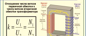
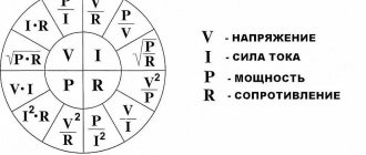
What determines the capacitance and charge of a capacitor?
The capacitance of a capacitor is a physical quantity by which its ability to perform its functional tasks is assessed.
The practical value of capacitance is expressed in the ability of an electrical device to accumulate charge.
The voltage on the plates directly affects the quantitative characteristics of the charge on the plates. The formula for determining capacity looks like
C = q/U,
where C is the capacitance of the capacitor,
q - means the amount of charge on one of the plates,
U is the potential difference on the plates. The given calculation formula is largely theoretical in nature.
There is another definition of capacity, which is more useful in a practical sense.
The formula C = єS/d indicates its relationship with the area S of the plates, the distance between the plates d and the properties of the dielectric є.
It follows from the formula that the larger the area of the plates, the greater the charge that can be placed on them and the greater the distance between the plates, the weaker the charged particles will be attracted to each other, increasing their chances of leaving the plate.
The maximum dielectric constant of the material located between the plates increases the capacitance of the capacitor without changing the overall characteristics.
Processes of charging and discharging capacitors.
We've figured out the device, now let's figure out what happens if we connect a DC source to the capacitor. On circuit diagrams, a capacitor is designated as follows:
So, we have connected the capacitor plates to the poles of the DC source. What will happen?
Free electrons from the first plate of the capacitor will rush to the positive pole of the source. Because of this, there will be a lack of negatively charged particles on the plate, and it will become positively charged. At the same time, electrons from the negative pole of the current source will move to the second plate of the capacitor. As a result, an excess of electrons will appear on it, and accordingly, the plate will become negatively charged. Thus, charges of different signs are formed on the plates of the capacitor (this is exactly the case we considered in the first part of the article), which leads to the appearance of an electric field that will create a certain potential difference between the plates of the capacitor. The charging process will continue until this potential difference becomes equal to the voltage of the current source. After this, the charging process will end and the movement of electrons along the circuit will stop.
When disconnected from the source, the capacitor can retain accumulated charges for a long time. Accordingly, a charged capacitor is a source of electrical energy, which means that it can release energy into an external circuit. Let's create a simple circuit by simply connecting the capacitor plates to each other:
In this case, a capacitor discharge current will begin to flow through the circuit, and electrons will begin to move from the negatively charged plate to the positive one. As a result, the voltage across the capacitor (the potential difference between the plates) will begin to decrease. This process will end at the moment when the charges of the capacitor plates become equal to each other, accordingly, the electric field between the plates disappears and current stops flowing through the circuit. This is how the capacitor discharges, as a result of which it releases all the accumulated energy into the external circuit.
How does a capacitor work?
A capacitor consists of two or more metal plates with a dielectric material between them. The electrons begin to move, but are unable to overcome the dielectric, causing an electrical charge to accumulate between the plates.
Paper coated with aluminum oxide, mica, electrolyte, ceramics and similar materials have good dielectric properties.
The charges on different plates are the same in magnitude, but opposite in sign.
Galvanometer
If you have a ballistic galvanometer, you can also determine the capacitance of the capacitor. To do this, use the formula:
C = α * Cq / U, where α is the galvanometer deflection angle, Cq is the ballistic constant of the device, U is the galvanometer readings.
Due to the drop in leakage resistance, the capacitance of the capacitors decreases. Energy is lost along with leakage current.
The methods for determining capacitance described above allow you to determine the health of capacitors. A significant deviation from the ratings indicates that the capacitors are faulty. A broken electrolytic radio element is easily determined by measuring the resistance. If the resistance tends to 0, the product is short-circuited, and if it approaches infinity, it means there is a break.
You should be wary of strong electrical discharge when connecting probes to large electrolytes. They can accumulate a powerful electrical charge from direct current, which is released with lightning speed by the discharge current.
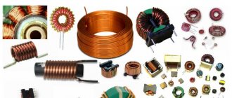
Types of capacitors
Capacitors differ in a number of parameters: by configuration, by the type of dielectric, by the material of the plates, by the type of change in capacitance (constant, variable, interlinear), by operating voltage. Below in the figure we consider the main types of electrical devices of various configurations.
Flat
The flat type of the device consists of two plates that are located parallel to each other. They are compact while maintaining large capacity.
The capacitance of a parallel-plate capacitor increases as the area of the plates increases and the distance between them decreases.
To calculate the capacitance of a flat capacitor, you should use the formula C = ε0 εS / d
Spherical
A spherical capacitor consists of two concentrically located spheres with a thin dielectric between them. The outer surface of the outer plate is grounded to create an electric field directly between the plates. Taking into account the geometry of the plates, the capacitance of a spherical capacitor is calculated using the formula
C = 4πεε0 Rr/ R - r, where R is the radius of the outer lining, r is the radius of the inner.
Cylindrical
A cylindrical capacitor is made of two hollow cylinders with different radii of their forming circles with a common axis. There is a dielectric between the outer surface of the small cylinder and the inner surface of the large one. To calculate the capacitance of a cylindrical capacitor, you can use the formula C = 2πєє0L/ ln (R2/R1),
where L is the length of the cylindrical plates,
R2 is the radius of the outer cylinder,
R1 is the radius of the inner cylinder,
ln - designation of logarithmic action.
What is a capacitor
A capacitor is a two-pole device that has a constant or variable capacitance value and low conductivity. This is a circuit element that serves as an energy storage device that forms an electric field; passive electronic component of any connection. It contains several metal electrodes or plates, between which there is a dielectric. It can have a package, tubular, disk, cast sectional and roll design.
Capacitor
The capacitor has a flat or cylindrical shape. A flat device consists of plates located relatively far apart from each other, and a cylindrical device consists of several hollow coaxial conducting cylinders with radii r1 and r2 (the main condition is r1 > r2).
Term from the textbook
Polar
Polar capacitors are devices that have polarity, namely plus and minus. It is important that the positive contact is connected to the “plus” of the power source, and the negative contact to its “minus”. Reversing the polarity can even lead to a capacitor explosion. Polar ones include tantalum, ionistors, and capacitors with an electrolytic dielectric.
Tantalum
Tantalum capacitors, which are of the electrolytic type, use sintered tantalum powder, tantalum oxide, as a dielectric, hence their name. Such a dielectric reduces leakage current to almost zero.
The disadvantage is the inability to work in high voltage electrical circuits.
A tantalum capacitor includes 4 elements - anode, dielectric, electrolyte and cathode.
Unlike electrolytic ones, tantalum ones have a lower self-inductance, so they can be used at high frequencies.
The compactness of tantalum devices allows them to be used as components of wiring diagrams.
Ionistors
Ionistors belong to the category of electrochemical capacitors. The design feature lies in the combination of the properties of a conventional capacitor and a battery. The space between the electrodes is filled with a solid electrolyte based on rubidium and similar materials. This design eliminates spontaneous discharge of the ionistor.
Rapid discharge and charging make it possible to use it in some types of electrical circuits instead of a battery.
The battery, unlike the ionistor, will require considerable time to charge. The capacitance of the ionistor has the highest value among all electrolytic devices.
The ionistor only works with a constant voltage source.
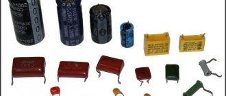
Electrolytic
Electrolytic capacitors, in which one of the plates is made in the form of aluminum foil, have become widespread. The other plating is a solid or liquid electrolyte that ensures the movement of charged particles to preserve the oxide film.
The capacity of an electrolytic capacitor is by far the largest in terms of the capacitance to volume ratio of the element.
Electrolytic elements are installed in filters, but polarity is important.
Compared to tantalum capacitors, electrolytic capacitors have a significant leakage current.
The processes of transfer of charged particles occur slowly, which increases the amount of heat generated. Hence overheating and low service life.
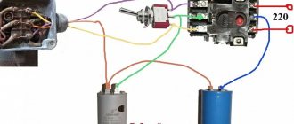
How to connect capacitors correctly?
Many novice electronics enthusiasts in the process of assembling a homemade device have a question: “How to connect capacitors correctly?”
It would seem why this is necessary, because if the circuit diagram indicates that a 47 microfarad capacitor should be installed in a given place in the circuit, then we take it and install it. But, you must admit that in the workshop of even an avid electronics engineer there may not be a capacitor with the required rating!
A similar situation may arise when repairing any device. For example, you need an electrolytic capacitor with a capacity of 1000 microfarads, but you only have two or three at hand with a capacity of 470 microfarads. Set 470 microfarads instead of the required 1000? No, this is not always acceptable. So what should we do? Go to the radio market several tens of kilometers away and buy the missing part?
How to get out of this situation? You can connect several capacitors and as a result get the capacitance we need. In electronics, there are two ways to connect capacitors: parallel and series.
In reality it looks like this:
Parallel connection Circuit diagram of parallel connection Serial connection Circuit diagram of series connection
It is also possible to combine parallel and serial connections. But in practice you are unlikely to need this.
Non-polar
Non-polar capacitors work correctly no matter how they are connected to an electrical circuit.
This is due to the similar structure of the materials that form the boundary between the plate and the dielectric. The sides are the same. All this leads to the fact that there is no need to observe polarity when installing the capacitor. As non-polar electrical devices, dry ones are mainly used, less often electrolytic ones, manufactured using modified technology.
Ceramic
Ceramic capacitors have high electrical performance, small dimensions and reasonable cost.
Elements are installed in the circuits of radio equipment. Ceramic capacitors are divided into
- with constant capacity
- tuning.
Elements with constant capacitance are installed in the circuits of generators and local oscillators. Tuning – used to adjust the parameters of oscillatory circuits. They are widely used due to the variety of capacities, a wide range of operating voltages, and standard sizes similar to ceramic devices from different manufacturers.
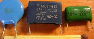
Film
A special feature of such devices will be a dielectric in the form of a film. The film is made from fluoroplastic, metallized paper, polypropylene, polycarbonate and similar materials. A metal film or foil is sprayed or pressed onto the dielectric.
Due to the large number of layers, an increase in area is obtained, and accordingly, the capacity increases significantly.
Among the advantages of a film capacitor, one should note the relatively high reliability and stability of the thermal state under loads caused by alternating current.
The disadvantages include the low value of dielectric permeability.
Film capacitors are used in DC circuits, all kinds of filters and resonant circuits.
Smd
In the control circuits of some types of boards, small SMD capacitors are used, shaped like small bricks. The radio element is installed on the board using the surface mounting rule. SMD devices come in the following types:
- electrolytic
- ceramic;
- tantalum.
Ceramic SMD capacitors with a dielectric with high permeability are marked with three letters. The first two letters indicate the lower and upper maximum permissible limits of the operating temperature range, the third letter is used to indicate deviations in the change in capacitance for the measured ranges.
The small size of Smd capacitors does not always allow marking to be applied to the case or it will be very small.
In such cases, you cannot do without a special measuring device, for example, a multimeter.
Where and what are they used for?
As already mentioned, it is difficult to find a circuit without capacitors. They are used to solve a variety of problems:
- To smooth out surges in network voltage. In this case, they are placed at the input of devices, in front of microcircuits that are demanding on power parameters.
- To stabilize the output voltage of power supplies. In this case, you need to look for them before leaving. Electrolytic cylindrical capacitors are often seen
- Touch sensor (touch pads). In such devices, one of the “plates” of capacitors is a person. Or rather, his finger. Our body has a certain conductivity. This is what is used in touch sensors.
- To set the required rhythm of work. The charging time for capacitors of different capacities is different. In this case, the charge/discharge cycle of the capacitor remains constant. This is used in circuits where it is necessary to set a certain rhythm of work.
- Memory cells. The memory of computers, phones and other devices is a huge number of small capacitors. If it is charged, it is one, if it is discharged, it is zero.
- There are starting capacitors that help “accelerate” the engine. They accumulate a charge, then release it sharply, creating the required “push” to accelerate the motor.
- In photo flashes. The principle is the same. First, the charge is accumulated, then released, but converted into light.
Capacitors are common and their applications are wide. But you need to know how to connect them correctly.
Variables
Variable capacitors (VCA) consist of some sections of metal plates. One of them moves smoothly in relation to the second. During movement, it turns out that the moving plates (rotor) fall into the gaps of the stationary plate (stator). Thanks to the process, the area of overlap of one plate with another changes, as a result of which the capacitance of the capacitor changes. The dielectric layer in this case is air.
Capacitors installed in small devices use a solid dielectric, such as fluoroplastic or polyethylene.
In old radios, the device was used to tune the oscillating circuit of a working radio station to a specific frequency.
Electric field in a dielectric
If a capacitor is NOT connected to a power source, the charge Q = CV on its caps will remain constant regardless of whether a dielectric is placed between them. If we denote C and E respectively, the capacitance of an empty capacitor and the value of the electric field between its caps, and C and E are the same values for a capacitor filled with a dielectric, we can write
From here, and based on the definition of dielectric constant ε, we obtain
Thus, it is clear that the field strength in the dielectric is ε times less than in vacuum.
This relation is general and applies to every fixed field E, regardless of its source.
Maximum operating voltage on capacitor
The voltage supplied to the capacitor should not exceed the maximum, as dielectric breakdown may occur and the element may fail.
To analyze the operation of a capacitor in an alternating current circuit, the amplitude voltage value should be taken as a criterion for comparison with the maximum possible value.
This means that if some maximum voltage DC WV is indicated on it, then in reality when connected to the network it should be 1.4 less.
How is capacitor voltage measured?
The voltage is reflected on the body of the equipment and shows at what level of energy it operates. The voltage of the capacitors is measured in farads. This is a unit named after Michael Faraday. One farad is a coulomb, or charge, passed through a conductor in one second at a current of one ampere. As a rule, farads and coulombs are not used for measurement in practice, because fractional quantities are more often used - micro-, nano- and picofarads.
Measuring the charge strength of a two-terminal network
Magnitude and value of capacitor loss
Capacitor leakage current is a critical factor to use, especially when applied to power electronics. The loss is directly related to the properties of the dielectric.
No dielectric is capable of insulating metal plates with a 100% guarantee.
A current will always pass through the insulator, less or more depending on the properties of the dielectric and energy will be lost. In addition to the insulating properties of the dielectric, the following factors influence the leakage current:
- ambient temperature;
- shelf life of the capacitor without voltage, temperature;
- the magnitude of the leakage current is directly proportional to the voltage applied to the plates.
You can restore the functionality of a capacitor after long-term storage by applying operating voltage to it for several minutes.
At this stage, the oxidizing layer accumulates again and restores the functionality of the capacitor.
Capacitor leakage current
The point is that no matter what the dielectric is, the capacitor will still discharge sooner or later, since, oddly enough, current still flows through the dielectric. The magnitude of this current is also different for different capacitors. Electrolytic capacitors have the highest leakage current.
Also, the leakage current depends on the voltage between the capacitor plates. Ohm's law already works here: I=U/Rdielectric. Therefore, you should never apply a voltage greater than the maximum operating voltage specified in the datasheet or on the capacitor itself.
Capacitor in an electric current circuit
The principle of operation of a capacitor is simple - voltage is applied and a charge is accumulated. The drive behaves differently in two versions of the electrical circuit.
Permanent
If current is applied to a circuit with a capacitor connected to it, the needle on the ammeter will move, after which it will quickly return to its previous position. This is due to the fact that the device is charging quickly and the current has disappeared. Direct current cannot pass through plates separated by a dielectric. The practical use of a capacitor in such a circuit raises many questions. In direct current conditions, the capacitor functions, but for a short time. Transient processes in the form of charging and discharging remove all doubts. In DC electronic circuits, capacitors are one of the most common components.
Variable
When connecting alternating voltage, the poles of the capacitor change plus to minus with the frequency of the voltage supply. In this case, electrons move first to one and then to the other. During such a change, excess charge remains on the plates, which actually creates a current in the external circuit.
The capacitor in the AC circuit acts as a resistor.
Capacitor
Before you figure out what the capacity of a simple capacitor is, you need to decide what this electrical element is. A capacitor is a radio-electronic part that can accumulate and release a certain portion of electrical charge. The device consists of the following elements:
- Cases. Often made of aluminum. It can be flat, spherical or cylindrical in shape.
- Covers (2 or more). They are made from metal plates or foil.
- Dielectric gasket. It is installed between the plates and serves as an insulator.
- Two or more output contacts for connecting the device to an electrical circuit.
This type of electric charge storage device works as follows.
- When an element is connected to a source of electric current, it acts as a conductor. At this moment, the electric current is at its maximum value and the voltage is at its minimum.
- Positive and negative charges (electrons and ions) begin to accumulate on the plates of the element. This way the device itself is charged. At the time of charging, the strength of the electric current gradually decreases, and the voltage, on the contrary, increases.
- After the amount of charge in the capacitor exceeds the permissible limit, it is discharged and the process begins to repeat cyclically again.
The basis for the performance of this device is its capacity. It is this parameter that determines the charge accumulation time and the total “capacity” of the device. The following figure below will help you understand how the simplest capacitor is indicated on the diagrams.
Electric capacitance, like the capacitors themselves, have found a wide range of applications. They are used as:
- Frequency filters.
- Pulse source for various photographic equipment.
- Smoothers of pulsating currents in rectifiers.
- Phase shifting elements for electric motors.
The use of capacitors in various fields is based precisely on the ability of the device to accumulate electrical charge. In more complex electrical equipment, these devices are used to uninterruptedly maintain a certain voltage in different data storage devices.
Capacitor resistance depending on
The resistance of the capacitor depends on the frequency of the voltage supplied to it and the capacitance value.
Frequencies and phase shift
A charge storage device of the same capacity exhibits different levels of resistance at different frequencies. It grows or decreases.
As the frequency of the input voltage increases, the resistance (also called capacitive) decreases.
At low frequencies there is a phase shift between the input voltage and the load voltage.
As frequency increases, the phase shift decreases.
When the frequency reaches a certain level, the phase shift tends to zero.
Xc = 1/ωС,
where ω is the circular frequency equal to the product 2πf,
C is the circuit capacity in farads.
Capacitor rating
The capacitance of a capacitor affects the charging and discharging process when alternating current passes through it.
A device with a smaller capacity will release charge faster and charge again.
The AC resistance will be higher than when charging and discharging slowly.
Hence the conclusion: capacitance is inversely related to the value of the capacitor.
Time required to charge the capacitor
Under ideal conditions, when the voltage source is powerful, there is no obstruction to the flow of electricity, the capacitor is flawless, the charging time of the capacitor will be 0.
In practice, at each section of the circuit there is explicit (resistors) or implicit (wires, voltage source, etc.) resistance. In this case, the charging time of the capacitor will depend on the resistance in the entire circuit and its capacitance.
At the very beginning of the charge, there is a lot of free space on the plates of the drive, and the voltage is zero. The initial current at this moment is maximum. As the capacitor is filled with charged particles, their flux gradually decreases, and U grows more and more slowly. When there is no free space left on the plates, the current will stop, the voltage will become maximum and equal to that of the source.
The exponential increase in energy in a capacitor is shown in the figure. The formula itself for the dependence of the voltage increase on the charging time is as follows:
U=Uc*[1-e(-t/τ)]
where Uс is the electromotive force of the source, t is the charging time, τ is the time constant equal to R*C (R is resistance).
During time τ, the charging of the capacitor will reach (1 – 1/e)*100% ≈ 63% of U.
For 3τ – up to (1 – 1/e3)*100% ≈ 95% of U.
For 5τ – up to (1 – 1/e5)*100% ≈ 99% of U.
The time it takes to charge the capacitor exactly to the source voltage level lasts indefinitely.
From the above formula for calculating voltage, you can calculate the time it takes to charge the drive to certain indicators:
t = – ln (1 – U/Uc) * RC
Charging a capacitor from a source of constant EMF
The process of charging a capacitor, discussed in the previous section, by transferring charge from one plate to another, is of exclusively theoretical interest, as a method for calculating the energy of a capacitor. In reality, capacitors are charged by connecting them to an EMF source, for example, to a galvanic battery.
Let a capacitor of capacitance C be connected to a source whose emf is equal to ε
(Fig. 145). The complete electrical connection of the circuit (including the internal resistance of the source) will be denoted by R. When the key is closed, an electric current will flow in the circuit, due to which an electric charge will accumulate on the capacitor charges. According to Ohm's law, the sum of the voltages across the capacitor (~U_C = frac{q}{C}) and resistor (U_R = IR) is equal to the source emf (varepsilon = U_C + U_R), which leads to the equation
(~IR = varepsilon - frac{q}{C}) . (1)
In this equation, the capacitor charge and current depend on time. The rate of change of capacitor charge is by definition equal to the current in the circuit (~I = frac{Delta q}{Delta t}), which allows us to obtain an equation describing the change in capacitor charge over time
(~R frac{Delta q}{Delta t} = varepsilon - frac{q}{C}) . (2)
You can also obtain an equation that directly describes the change in current in a circuit over time. To do this, based on equation (1), we write the equations for small changes in input quantities
(~Delta varepsilon = Delta (IR) + Delta left (frac{q}{C} right )) .
Formally, this operation can be described as follows: equation (1) should be written for two moments of time t
and ( t + Δ t ), and then subtract the first from the second equation. Since the source emf is constant, its change is zero Δ ε = 0, the circuit resistance and capacitance of the capacitor are constant, so they can be taken out of the sign of the change Δ, so the resulting equation takes the form
(~R Delta I = - frac{1}{C} Delta q) .
Finally, we divide it by the period of time during which these changes occurred, as a result we obtain the desired equation (taking into account the relationship between the current strength and charge changes)
It will be interesting➡ Circuit breakers
(~frac{Delta I}{Delta t} = -frac{1}{RC} I) . (3)
The mathematical meaning of this equation indicates that the rate of decrease in current is proportional to the strength of the current itself. To uniquely solve this equation, it is necessary to set the initial condition - the value of the current at the initial moment of time I
0 = I(0).
We became acquainted with equations of this type in the “mathematical digression”, so here we will analyze it briefly.
At the initial moment of time, when the charge of the capacitor is zero, the rate of charge increase (that is, the current strength) is maximum and equal to (~I_0 = Delta left (frac{Delta q}{Delta t} right )_0 = frac{varepsilon}{R} ).
Then, as the charge accumulates, the current strength will decrease, when the voltage on the capacitor becomes equal to the source emf, the capacitor charge reaches its maximum stationary value (~overline{q} = Cvarepsilon) and the current in the circuit stops.
Schematically, the time dependences of the capacitor charge and current in the circuit are shown in Fig. 146. To estimate the charging time of a capacitor, we can assume that the charge increases to a maximum value at a constant rate equal to the current strength at the initial time. In this case
(~tau = frac{overline{q}}{I_0} = RC) . (4)
A similar estimate of the disappearance of the current, obtained on the basis of equation (3), leads to the same result.
Strictly speaking, the charging time of the capacitor described by equation (2) is equal to infinity. This paradox can be eliminated if we take into account the discreteness of the electric charge.
In addition, the charge of a capacitor connected to the battery changes randomly over time and fluctuates, so the equation under consideration describes some average characteristics of the process.
However, the resulting estimate of the RC time is widely used in approximate calculations; it is often simply called the capacitor charging time
Let us now consider the transformations of various forms of energy in this process. It is clear that the cause of the current in the circuit and, as a consequence, the charging of the capacitor are external forces from the source.
At first glance, the energy balance includes a certain contradiction: if the source imparted a charge q to the capacitor
, then the external forces did the work A 0 = qε, and the energy of the capacitor became equal to (~W = frac{q2}{2C} = frac{q varepsilon}{2}), which is half the work done by the source.
The contradiction disappears if we take into account that during the charging process an electric current flows through the circuit, therefore a certain amount of heat is released at the resistor, that is, part of the source energy is converted into heat. Let's mentally divide the charging time into small intervals Δt
i (i = 1,2,3…). Let us rewrite equation (1) in the form
(~varepsilon = IR + frac{q}{C}) , (5)
and multiply it by the value of a small portion of charge transferred over a short period of time Δt
i, Δ qi = I iΔ ti . As a result we get
(~varepsilon Delta q_i = I_i R Delta q_i + frac{q_i}{C} Delta q_i) . (6)
Here we denote q
i is the charge of the capacitor before transferring the portion of charge under consideration. Each member of the resulting equation has a clear physical meaning: [~varepsilon Delta q_i = delta A] - the work of external forces to move a portion of the charge Δ qi; [~frac{q_i}{C} Delta q_i = Delta W_C] - an increase in the energy of the capacitor with increasing its charge by Δ qi;[~I_i R Delta q_i = I2_i R Delta t_i = delta Q] - the amount of heat released on the resistor when a portion of charge Δ q i flows.
Thus, the law of conservation of energy, expressed by the balance equation (6) for a short period of time turns out to be fulfilled, therefore, it will be fulfilled for the entire charging process.
Let's sum up expression (5) over all charging time intervals, resulting in: [~sum_i varepsilon Delta q_i = varepsilon overline{q} = A] - the total work of external forces to transfer an electric charge equal to the stationary charge of the capacitor;[~sum_i frac {q_i}{C} Delta q_i = frac{overline{q2}}{2C} = frac{varepsilon overline{q}}{2} = frac{C varepsilon2}{2}] is the energy of the charged capacitor;
finally, (~sum_i I_i R Delta q_i = sum_i I2_i R Delta t_i) - the amount of heat released by the resistor.
Taking into account equation (3) and the formulas from the “mathematical digression”, the last sum can be expressed as
(~Q = R sum_i I2_i Delta t_i = R frac{1}{2} I2_0 tau = R frac{1}{2} left ( frac{varepsilon}{R} right )2 RC = frac{C varepsilon2}{2 }) . (6)
This amount can be calculated graphically. Formula (1) specifies the dependence of the voltage across the resistor (U_R = IR) on the charge of the capacitor. This dependence is linear; its graph (Fig. 147) is a straight line segment.
In a short period of time, a small charge Δq will flow through the resistor
i, in this case an amount of heat will be released (~delta Q_i = I_i R Delta q_i), which is numerically equal to the area of the narrow strip highlighted in the figure.
The total amount of heat released during the passage of the entire charge is numerically equal to the area of the triangle under the graph of the dependence U
R(q), that is
Series and parallel connection of capacitors
The most popular type of capacitor connection is parallel. With this connection, the electrical capacity increases, but the voltage remains original.
Several capacitors can be connected to one point.
Since the electrical capacitance of the capacitors is equal to the area of the plates, the total capacitance with this type of connection is proportional to the sum of the capacitances of all capacitors in the circuit.
Message = C1+C2.
When capacitors are connected in series, the total capacitance decreases and the operating voltage of the capacitor increases.
The capacitors are connected so that only the first and last have access to the emf/current source of one of their plates. The charge is the same on all plates, but the outer ones receive a charge from the source, and the inner ones are formed due to the separation of charges that previously neutralized each other. We can calculate the capacitance of a series connection of two capacitors using the formula
Message = C1*C2/ C1+C2.
Application of capacitors
There is a capacitor in every modern device. Let's look at two of the most obvious examples.
Example time - flash
Without a capacitor, the flash in the camera would not work as we are used to, but with long delays, and would also quickly drain the battery. The capacitor in this case works like a battery. It accumulates charge from the battery and stores it until needed. When we need a flash, the capacitor discharges so that it fires and the bird flies out.
Calculation formulas
Capacitance measurements are carried out using a specially derived formula. Electrical capacitance (C) is the ratio of the imparted charge (Q) to the resulting potential (U). The formula used to measure capacitance is: C=Q/V. The unit of measurement is the farad, which is denoted by the letter F. A capacitance of 1 farad will store a charge q = 1 coulomb with a voltage across the plates U = 1 Volt. Since capacitors have different types, the formulas are also different.
Through mathematical expressions
The mathematical expression for determining the capacitance of the capacitor C = q*U in SI units of each of the physical quantities included in the formula determines the value of 1 farad.
How does capacitance depend on the dielectric medium?
The effect of an insulator on the capacitance of a capacitor depends on the conductive properties of the substance inside that pad. The ability of an interplate conductor to insulate is called dielectric constant. Taking into account the characteristics of the dielectric, the formula for the capacitance of a flat device will become: C = є0є S/d, where under the letter є is the value of the dielectric constant of the insulator, and є0 is a constant value equal to the dielectric constant of vacuum (air).
In practice, a coefficient is used that indicates how many times the dielectric used reduces the electric field compared to air.
Table:
Units
The physical quantity determined by the ratio of the charge q of one of the capacitor plates to the voltage between the plates of the capacitor is called the electrical capacity of the capacitor:
With a constant arrangement of the plates, the electrical capacity of the capacitor is a constant value for any charge on the plates. The unit of electrical capacity in the international system is farad (F). An electrical capacitance of 1 F is possessed by a capacitor whose voltage between the plates is equal to 1 V when the plates are charged with 1 C of opposite charges. . In practice, submultiple units of electrical capacitance are widely used: microfarads (μF), nanofarads (nF) and picofarads (pF):
- 1 µF = 10-6F;
- 1 nF = 10-9F;
- 1 pF = 10-12F.
The electrical capacity of a capacitor is directly proportional to the area of the plates and inversely proportional to the distance between the plates. When a dielectric is introduced between the plates of a capacitor, its electrical capacity increases by e times. If two conductors isolated from each other are given charges q1 and q2, then a certain potential difference Δφ arises between them, depending on the magnitude of the charges and the geometry of the conductors.
The potential difference Δφ between two points in an electric field is often called voltage and denoted by the letter U. Of greatest practical interest is the case when the charges of the conductors are equal in magnitude and opposite in sign: q1 = – q2 = q. In this case, we can introduce the concept of electrical capacitance.
The electrical capacity of a system of two conductors is a physical quantity defined as the ratio of the charge q of one of the conductors to the potential difference Δφ between them. The value of electrical capacitance depends on the shape and size of the conductors and on the properties of the dielectric separating the conductors. There are configurations of conductors in which the electric field is concentrated (localized) only in a certain region of space.
Such systems are called capacitors, and the conductors that make up the capacitor are called plates. The simplest capacitor is a system of two flat conducting plates located parallel to each other at a small distance compared to the size of the plates and separated by a dielectric layer.
Such a capacitor is called a flat capacitor. The electric field of a parallel-plate capacitor is mainly localized between the plates (Figure 1); however, a relatively weak electric field also arises near the edges of the plates and in the surrounding space, which is called the stray field.
In a number of problems, one can approximately neglect the stray field and assume that the electric field of a flat capacitor is entirely concentrated between its plates (Figure 2). But in other problems, neglecting the stray field can lead to gross errors, since the potential nature of the electric field is violated.
It will be interesting➡ What is an electric field: an explanation in simple words
According to the principle of superposition, the field strength created by both plates is equal to the sum of the strengths and fields of each of the plates. Outside the plates, the vectors and are directed in different directions, and therefore E = 0. The surface charge density σ of the plates is equal to q/S, where q is the charge and S is the area of each plate. The potential difference Δφ between the plates in a uniform electric field is equal to Ed, where d is the distance between the plates. From these relations we can obtain a formula for the electrical capacitance of a flat capacitor:
Thus, the electrical capacity of a flat capacitor is directly proportional to the area of the plates (plates) and inversely proportional to the distance between them. If the space between the plates is filled with a dielectric, the electrical capacity of the capacitor increases by ε times. Examples of capacitors with different plate configurations include spherical and cylindrical capacitors.
Electrical capacity is a characteristic of a conductor, a quantitative measure of its ability to hold an electric charge. In an electrostatic field, all points on the surface of a conductor have the same potential.
The potential φ (counted from the zero level at infinity) is proportional to the charge q of the conductor, i.e. the ratio of q to φ does not depend on q. This allows us to introduce the concept of electrical capacity. From an isolated conductor, which is equal to the ratio of the charge of the conductor to the potential:
C = q/ φ
Thus, the greater the electrical capacity, the more charge a conductor can accumulate at a given φ. Electrical capacity is determined by the geometric dimensions of the conductor, its shape and the electrical properties of the environment (its dielectric constant) and does not depend on the material of the conductor. In particular, the electrical capacity of a conducting ball in a vacuum is equal to its radius. The presence of other bodies near a conductor changes its electrical capacity, since the potential of the conductor also depends on the electric fields created by charges induced in surrounding bodies due to electrostatic induction.
In the unit system SGSE electrical capacity is measured in centimeters, in SI - in farads: 1F = 9 * 1011 cm. The concept of electrical capacity also refers to a system of conductors, in particular two conductors separated by a thin layer of dielectric - an electrical capacitor. Electrical capacity of a capacitor (mutual capacitance of its plates)
С = q/ (φ1 – φ2),
where q is the charge of one of the plates (the charges of the plates are equal in absolute value), φ1 – φ2 is the potential difference between the plates. The electrical capacity of a capacitor is practically independent of the presence of surrounding bodies and can reach a very large value with small geometric dimensions of the capacitors.
How to measure capacitance
There are a number of ways to measure capacitance of a capacitor using instruments and various techniques. The article describes the use of a multimeter, oscilloscope, tester and bridge meters.
Multimeter
In the beginning, before you start measuring the capacitance of the capacitor, it must be discharged until the current completely disappears.
As an example: do this by shorting the terminals with a screwdriver.
If you neglect this nuance, the multimeter may break.
You can measure capacitance using a multimeter as follows: activate the “Cx” mode and set the measurement limit to 2000 pF, if any. On a standard device it is equal to 20 µF; Install the capacitor into the appropriate sockets in the multimeter or use probes to connect the capacitor. The capacitance value will be displayed on the device screen.
Oscilloscope
To measure, you will need, in addition to an oscilloscope, to assemble a circuit from the capacitor being tested, a resistor and a sinusoidal oscillation generator.
The connection points of the oscilloscope to the circuit are located before the resistor and after the capacitor.
The oscillator frequency changes until sinusoidal curves of equal amplitude are obtained on the oscilloscope screen. This is done for measurement accuracy. Imagine how to calculate the capacitance of a capacitor using amplitude voltage values? To do this, you need to use the formula UR/UC*2πfR and substitute the measured values into it. With its help, the leakage current of the capacitor is also calculated indirectly - by reducing the voltage across a previously known resistance. The oscilloscope is capable of calculating the capacitance of capacitors from 20 pF to 200 mkF.
A tester that does not have a direct function
To find an option for determining capacity using a tester without a capacity measurement function, you should pay attention to the formula for the instantaneous value of the current during charging or discharging i = C dU/dt.
The point here is that in addition to the tester and stopwatch, you should assemble a circuit with a power source,
a capacitor and a resistor with high resistance to increase the duration of the charging or discharging process. After taking all the readings from the tester and stopwatch, you can fairly approximately calculate and find out the capacity. Knowing how to determine the capacitance of a capacitor with modern instruments, it will not be difficult to understand the device from the times of the USSR. The display does not display numbers, but rather the deviation of the arrow, which is important to monitor closely. Capacitance measurements are carried out only on a discharged capacitor. Lead the probes to the contacts of the capacitor; if it is working, the arrow will initially deflect, after which it will take its original position as it charges. The speed of movement of the arrow depends on the volume of the container. If the tester's needle does not budge, or this value is minimal, or deviates and hangs in one position, this is an indicator of a faulty capacitor.
Bridge meters
The capacitance of the capacitor is measured by comparison with the reference capacitance. Why is a bridge circuit performed, where one arm works with a reference electrical device, the other with the one being tested. Bridge readings can be implemented on digital media.
Rated voltage
The second most important characteristic after capacitance is the maximum rated voltage of the capacitor. This parameter indicates the maximum voltage that the capacitor can withstand. Exceeding this value leads to “punching” of the insulator between the plates and a short circuit. The rated voltage depends on the insulator material and its thickness (the distance between the plates).
It should be noted that when working with alternating voltage, it is the peak value (the highest instantaneous voltage value per period) that needs to be taken into account. For example, if the effective voltage of the power supply is 50V, then its peak value will be over 70V. Accordingly, it is necessary to use a capacitor with a rated voltage greater than 70V. However, in practice, it is recommended to use a capacitor with a voltage rating of at least twice the maximum possible voltage that will be applied to it.
Capacitor markings
On the body of each capacitor there is a special marking - a letter and a number. Compared to resistors, capacitor markings indicating capacitance and capacitance deviation code are quite complex and varied. Sometimes the designations are written in capital letters - MF (microfarads), fd - farads. There are also positive and negative symbols on the housing to help determine the polarity of the capacitor.
Ways to designate a capacitor
The unit of measurement for the capacitance of a capacitor is the farad, so the letter Ф or F must be present on the body of the element:
- 1 millifarad = 10-3 farads = 1mF;
- 1 microfarad = 10-6 farads = 1 µF;
- 1 nanofarad = 10-9 farads = 1 nF;
- 1 picofarad = 10-12 farads = 1 pF.
If the element is not marked with a nominal value, then the integer value indicates that the capacity is indicated in picofarads. On the case, the capacity is indicated with a deviation; if the letter J is indicated, then the deviation range is less than 5%, the letter M is 20%.
Imported capacitor code
Imported devices, just like Russian ones, are marked in accordance with international standards. This regulatory document requires the application of a three-digit code. The first two digits indicate the capacitance in picofarads. The third digit indicates the number of zeros, for example, if the capacitance is less than 1 picofarad, the digit will look like “0”.
Code for surface mount capacitors
The marking of electrolytic SMD capacitors consists of capacitance and operating voltage. For example, 108V, where an electrical capacity of 10 pF and an operating voltage of 8 Volts are encoded. The plus sign is next to the stripe. There are three main encoding methods: a code of two or three characters (letters or numbers) that indicate the operating voltage and rated capacity. Indicators are indicated by a letter, and the number is a multiplier; four characters indicating voltage and rated capacitance. The first letter is the operating voltage, the next characters are the capacity in picofarads, the last digit is the number of zeros;
if the body area is large, the code is placed on two lines. The top line is the capacitance rating, the bottom line is the operating voltage.
Non-polar capacitors
Non-polar capacitors include capacitors for which polarity is unimportant. Such capacitors are symmetrical. The designation of non-polar capacitors on electrical circuits looks like this.
capacitor designation in the diagram
Variable capacitors
These types of capacitors have an air dielectric and can change their capacitance under the influence of an external force, such as a human hand. Below in the photo are Soviet types of such variable capacitors.
variable capacitors
The modern ones look a little prettier
trimmer capacitors
A variable capacitor differs from a trimmer only in that the variable capacitor is turned more often than a trimmer. They turn the trimmer once in a lifetime)
In the diagrams they are designated as follows.
variable capacitor designation on the diagram
On the left is variable, on the right is tuning.
Film capacitors
Film capacitors are the most common of the large family of capacitors. They are named so because instead of a dielectric, a thin film is used here, which can consist of polyester, polypropylene, polycarbonate, Teflon and much more. Such capacitors range from a nominal value of 5 pF to 100 µF. They can be made according to the burger principle
And also according to the principle of roll
Let's look at the K73-9 Soviet film capacitor.
K73-9 Soviet capacitor
What's inside? Let's see.
As expected, a roll of foil with a dielectric film
what's inside a capacitor
Ceramic capacitors
Ceramic capacitors are capacitors that are made of ceramic or porcelain that are plated with silver. Take a square or round disk, spray silver on both sides, draw out the leads and voila! The capacitor is ready! That is, there is the simplest flat capacitor, which we talked about earlier in this article.
Would you like to get more capacity? No problem! Put the discs in a sandwich and increase the capacity
Ceramic capacitors may look like this:
ceramic capacitors
ceramic teardrop capacitors
SMD capacitors
SMD capacitors are ceramic capacitors that are built like a sandwich.
structure of SMD capacitor
They are used in microelectronics because they are tiny in size and easy to industrially produce using robots that automatically place SMD components on the board. You can easily find this type of capacitor on the boards of your mobile phones, on computer motherboards, as well as in modern gadgets.
Gaussian generalized law
When describing the Coulomb force between point charges in a dielectric, the electric permittivity of the vacuum was multiplied by the dielectric permittivity and instead of ε we used the product ε ε. We can generalize this procedure and apply it to Gauss's law, where the center through which the field penetrates is not a vacuum, but a dielectric. Then we know Gauss's law
we can write in the form
we obtain the final form of the generalized Gauss law
Gauss's law in this form applies in vacuum, where ε = 1, and in dielectrics. The charge Q in this equation, as before, represents the net charge contained within the closed surface, after which integration occurs.
In a dielectric capacitor, the net charge is the difference between the load accumulated on the cap q1 = σA and the polarization charge (with opposite sign) induced in the surface layer dielectric q2 = -σ and A. If we use Gauss's law for this structure, then we assume that the charges accumulate on the adjacent surfaces of the cap and dielectric, and this field does not extend beyond the capacitor caps. A natural choice of Gaussian surface after which we integrate the flux is a rectangular prism or a cylinder surface. The base of rectangular prism A is parallel to the surface of the cover. One base is on the outside of the cap (where there is no field) and the other is inside the dielectric.
Gauss's law in the form presented above is one of Maxwell's four equations that describe all electrical, magnetic and optical phenomena. Maxwell's equations are the fundamental laws of electrodynamics, and none of them can be derived from simpler laws. If there were even more fundamental rights, they would certainly be presented here. These equations are the result of creative inspiration and enlightenment of their creators Gauss, Faraday and Ampere. Maxwell introduced them to the ingenious concept of “displacement current,” which we will talk about a little later, which made it possible to unify the structure of these equations and extend them to the case of electromagnetic and, therefore, light waves.