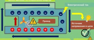
Current strength is a quantity that characterizes electricity. In addition to it, power, voltage, and frequency are distinguished. It is measured in amperes, and it is designated, both in the Russian and in the international system of units (SI), by the symbol “A”. Knowing this value makes it clear how many charged particles rush through the cross-section of the wire at a certain instant. That is, what is the intensity of the flow of electricity in the conductor. This can be compared to the pressure of water in hoses. Only instead of water, electrons flow in the conductors. The greater the “pressure” of electrons, the greater the current value.
To better understand the meaning of current, let's again compare electricity and water in hoses. If the water hoses are of small diameter and the pressure is strong, the hoses will not hold up and will burst. The same thing happens with wires. If the current in the wires to which the electrical appliance is connected is greater than they can withstand, the wires will simply burn out. This principle is the basis for the operation of fuses, which, by burning themselves, protect electrical wires from burning out. Therefore, in order to understand whether it is worth connecting the device to the electrical network, you need to know the critical current values that the wiring can withstand.
You can measure the current with a multimeter. This device can also make other measurements characterizing electric current, but now we will talk specifically about determining its strength.
Types of Multimeters
All devices, according to their design and principle of measuring current indicators, can be divided into two types:
- Analog testers.
- Digital multimeters.
Briefly about each type of measuring device.
Analog multimeters
The main difference between analog and digital devices is the presence of a digitized scale with an arrow. They are very easy to use and quite cheap. But their disadvantage is considered to be the presence of errors in the readings. Although this can be corrected using a tuning resistor. But, all the same, it is unlikely that it will be possible to achieve accuracy comparable to digital instruments. And in some cases, this is really necessary.
Digital multimeters
Since the presence of a scale with an arrow is mentioned as one of the main differences between analog devices, it is logical to assume that they are absent in digital devices. And indeed it is. The measurement results are displayed on the display, which can be LED or liquid crystal, in the form of specific numbers.
As already mentioned, the main advantage of digital testers is the accuracy of current measurement. In addition, they are not much more difficult to use than analog ones. Even a beginner can cope with measurements after a short instruction. The downside is the higher cost of a digital device.
How to measure alternating current with a multimeter
It happens that you need to check the electrical network, for example, for a house with several apartments. If you can measure the AC current, it will help you make proper wiring repairs.
And again you cannot do without a load, and again a light bulb can play its role.
Instructions on how to measure alternating current with a multimeter:
- We connect the wires to the required holes on the multimeter.
- Select the desired measurement function on the multimeter and, if necessary, the signal strength.
- We connect the selected load element in series with the meter to the socket.
- Let's look at the readings. The light starts to burn.
You learned how to measure current with a multimeter.
We wish you safe and accurate measurements!
Multimeter design
The device has several sockets used to measure electrical circuit parameters. In addition to these sockets, the device always has an output for a black wire. This socket is indicated on the multimeter body by the inscription “COM” or a “minus” sign. The black wire is always connected to ground. The second, red, wire is potential or “positive”. Its nest is determined depending on certain measurements. On the case, all the sockets are marked with corresponding symbols, so you need to try very hard to confuse them and take measurements of the wrong things. When measuring the current value, the red wire is inserted into the connector with the symbols “VΩmA”.
There is also a rotating knob on the body that sets the measurement limit. Digital meters have more limits than analog multimeters. In addition, they can be equipped with additional options, such as a sound or light signal.
Before measuring, you need to familiarize yourself with the data of the multimeter. This can be found in the technical documents that normal sellers attach to the electrical goods they sell. In addition, characteristics are often applied to the housing of electronic devices. You need to make sure that the upper limit of the multimeter is higher than the number of amps that may be in the network. So, it will not be possible to measure with a device whose maximum is 50 A, and the electric current indicator is 200 A. If you try to do this, the multimeter will simply burn out after connecting.
Multimeter dt9205a instructions for use
This model is very close to the previous one in terms of characteristics.
The same rubber body, the same probes are not of high quality (we recommend immediately replacing them with silicone). Warning: when purchasing silicone probes, it is better to check the correspondence between the diameter of the connector and the socket in the multimeter; some options simply do not fit completely and make it impossible to take measurements.
The main advantages of the device include:
- various measurement modes - from current to capacitors;
- presence of the “phase search” mode. With this option, the red probe is transferred to a device in the studio (for example, an outlet), and the black one is grounded to your own skin. When the phase is in the first digit on the display, the unit of measurement is shown;
- The stand for inclined installation, however, is not very stable.
User disadvantages include insufficient measurement accuracy and fluctuation error: at lower measurement values, the error is larger.
Preparing for work
First, you need to turn the switch handle to the marks of the sector indicated by the symbol “A”. To measure DC and AC values, different sectors are provided. They can be indicated by the symbols:
- three dots under a straight horizontal line - for direct current;
- wavy line - for variable.
The letter designations look like this:
- "DCV" - for permanent;
- "ACV" - for alternating current.
Care and compliance with the instructions when taking measurements will help you avoid mistakes and not break the multimeter.
Next you need to insert the cables into their sockets. Black - with the designation “COM” or “−”. Red with the designation “VΩmA”. There are contacts at the other ends of the cables. They will connect to the measured network.
What are amps
You should brush up on the definition of current, which is expressed in amperes. From a physics course we know that the strength of the current is determined by the amount of charge transferred through the volume over a certain period of time. This is not clear and not always clear.
It is easier to accept that current is the amount of heating of the elements of an electrical circuit. The greater the current, the greater the amount of heat will be released.
A large number of household and industrial appliances and devices use the heating property of current:
- Heating devices (electric stoves, kettles, irons).
- Incandescent lamps (glow from an overheated filament).
The simplest electric boiler.
Fuses used for short circuit protection also use the heating property of current. In fuses, this is the burnout of a thin calibrated wire; in circuit breakers, this is the bending of a bimetallic plate.
Fuse device
Measurement process
To measure, you need to connect to the open circuit between the network and the connected device that consumes current. The connection is made in series, as opposed to voltage measurement.
As it became clear, to connect to the circuit under test, it needs to be broken. This is done in several ways:
- You can disconnect the output by soldering the contacts;
- unscrewing the screw connections;
- cutting the wires with wire cutters.
Thus, the multimeter becomes an integral part of the electrical circuit. After correct connection, the arrow will show the current strength in the circuit. And the display will display specific numbers.
Introduction to multifunctional devices
Although different models of multimeters may differ in functionality and technical characteristics, their basic functions are the same. This means that all devices can measure voltage, current and resistance. Additionally, for example, it may be possible to test transistors.
In addition, testers can be electronic , where the readings are displayed on a digital display, or analog, equipped with an arrow that displays the value of a particular measurement.
Electronic multimeter
The appearance of electronic testers is quite similar, regardless of the diversity of the model range. At the top there is a digital liquid crystal display. Just below is a multi-position function switch containing the following positions:
Just below there are three connectors where you need to insert probes. And it needs to be done correctly. So, the black wire must be connected to the connector marked COM. Red is connected depending on what needs to be measured. It is connected to the connector marked “V Ω mA” when it is necessary to measure resistance, network voltage or current up to 200 mA. When measuring current strength greater than 200 mA, the red wire must be connected to the connector marked “10 ADC”. Otherwise, the fuse may burn out and even the device itself may fail.
Analog testers
There are also multimeters called dial or analog. Unlike electronic ones, the measured values here are determined using a scale with an arrow, which indicates the required parameter. They are less convenient to use. And the reading error is significantly lower than that of their electronic counterparts. They are also much more sensitive to mechanical influences and shocks - the frame on which the arrow is mounted can easily fail even from a strong shake.
But despite the fact that in most cases they are inferior to electronic ones, in some cases they may be preferable in operation.
Measuring current with an electronic multimeter
One of the directions of the tester is measuring current strength. To understand how to measure amperes with a multimeter, you need to know what kind of current, alternating or direct, the work will be done with. It's also a good idea to know the range over which measurements are taken. If you cannot obtain such information, then it is better to insert the red wire into the connector with a higher value, i.e., marked “10 ADC”. The switch also needs to be set to the highest possible value. This will prevent damage to the device in case of high current.
If the value displayed on the display is too low, then you can move the red wire to the “V Ω mA” connector, but also with the switch position at the highest values. When the value is still low, it is worth turning the switch to a lower setting until the measured current becomes adequate.
When measuring current, the device is connected to the circuit in series, which must be taken into account.
Measurement with a voltage tester
When measuring voltage, as well as measuring current, you need to know how to properly use a multimeter when carrying out such work. Here, too, it is necessary to pay attention to what kind of current we are dealing with - alternating or direct. Already guided by this, it is worth looking at what value needs to be set by the switch. For example, if we consider measuring the voltage in a simple outlet, we know that we mean an alternating current of approximately 220 volts. This means that the switch position must be set to an alternating voltage above this value. For example, 600 or 750 V, depending on the tester model.
DC voltage measurements are performed in a similar manner. If you do not know how many volts are in the circuit, then you should set the switch to a higher position, gradually reducing it to the most suitable values.
Unlike measuring current, when the device is connected in series, when measuring voltage, it must be connected in parallel. This is an important point to know how to use a voltmeter.
Determination of circuit resistance
Resistance measurement work can be considered the safest. It is extremely difficult to damage the device in any way here. The main thing is to know how to work with a multimeter in order to correctly determine the resistance. The main point to consider is the need to relieve tension before starting measurements. And here it’s not so much a matter of safety as the accuracy of the data obtained. Even a simple battery can significantly distort the accuracy of the readings.
You can set the switch to any position for measuring resistance in the “Ω” sector. Now that the probes are fixed at the ends of the conductor, the resistance of which needs to be known, you can look at the display indicators. There may be two options here:
- Indications “1”, “OL”, “OVER” - it is necessary to set a higher range, as overload occurs.
- Reading “0”—the range needs to be reduced.
In other cases, the resistance value of the conductor or semiconductor being tested will be displayed.
Features of measurements
There are several points that are tricks of professionals that they use when taking measurements. One of them is to use a device with a certain resistance with a multimeter. It could be an ordinary light bulb or a resistor. They protect the measuring device from burning out when excessive current is supplied.
If, when connecting the multimeter to the circuit, the current indicators are not displayed, then you need to check whether the limit is selected correctly. You can try lowering the limit by lowering it one more position. If nothing has changed, then the limit is reduced again. This must be done until the value obtained during the measurement appears on the device indicator.
Measurements must be taken quickly. The duration of contact with the electrically conductive cable should not exceed 2 seconds. This mainly concerns measurements of small-capacity power supplies. Prolonged contact results in discharge of the battery or accumulator.
Checking the power supply
How to check amps with a multimeter on a power supply? This is also done to break with the obligatory application of load. The principle itself differs little from checking other sources. It is only necessary to note that power supplies have quite a lot of power, so measurements should be carried out quickly, avoiding heating the wires of the multimeter probes.
As we can see, a multimeter can be very useful in everyday life and is in demand in completely different areas, so obtaining the most minimal knowledge on its use will not be superfluous at all.
We check small power supplies for various equipment - cash registers, cameras, cell phones, etc. - i.e. output current
- since in some cases the presence of output voltage - voltage DOES NOT ALWAYS guarantee full functionality of the power supply.
"Breaking the Load"
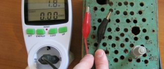
— we set the tester mode switch as in the photo — the maximum value for this tester is 10 Amps — accordingly, it is impossible to measure power supplies with a power of more than 10 Amps.
- We switch the right probe to the socket on the left (to measure current, you always need to not only change the mode, but also switch the probes or, as in this case - this model of the multimeter - one extreme probe).
- Next, we break the circuit - if it is impossible to open the case, simply cut one strand of the supply wire and close the circuit with a multimeter, i.e. one wire - one tester probe to the battery terminal (or one end of the cut wire from the power supply) - the second to the supply circuit, i.e. wire from the power supply (or the other end of the cut wire), i.e. We simply close the circuit from the power supply to the device via a multimeter.
- At the same time, we can see that if the energy consumer in this case, the battery is completely discharged, then the current strength can be twice as high as that indicated on the power supply.
- As charging progresses, if measured again after some time, the current will decrease as the battery reaches full charge. As soon as the battery is fully charged, we will see that the current from the power supply without load from the consumer is negligible - tends to zero. This is not a sign of a malfunction. You just need to measure under load - i.e. when the power supply powers the consumer - the battery.
- ATTENTION: YOU NEED TO MEASURE WITHIN 1-2 SECONDS, WITH HIGH POWER OF THE POWER SUPPLY 3-5 AND HIGHER AMPERES EVEN AT 12 VOLTS POWER SUPPLY VOLTAGE - THE WIRES INSTANTLY - EVEN IN A SECOND I HEAT UP TO 60-70 DEGREES.
Just in case, I repeat - we do not measure 220V alternating current from an outlet, but one already converted to constant current with a rated voltage of 3 - 5 - 10 - 12 Volts and a corresponding current strength of 1-3 amperes (as a rule, all this is written on the label on the unit itself nutrition).
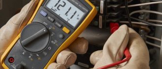
The photo below shows a multimeter in the current measuring position.
Photo instructions for checking the operation of the power supply, a tester for checking power supplies - the position of the mode switch and multimeter probes are shown in the photo:
The diagram is a method for checking the power supply for operability - for a break.
Charger and adapter measurements
Battery rechargers and power supplies are used with many modern gadgets. True, their purpose is different. Power supplies are designed to convert voltage to one suitable for the operation of the connected gadget. The charger is used to replenish batteries with electricity. It is necessary to know their characteristics in order not to damage an expensive device in case of failure of a standard device.
So, to measure current values in a circuit with an adapter or charger, you need to set the measurement limit in the range from 1 A to 10 A. The multimeter is connected in series to the circuit. If the readings are zero, you need to swap the probes or clamps.
How to measure voltage
For a person who has certain skills and knowledge in electrical engineering, it will not be difficult to take measurements using a multimeter. For those who have never worked with this type of device, below is how to use a standard multimeter.
Important! All work must be carried out by specialists or people with certain skills in electrical engineering. Remember that electric shock is life-threatening!
Constant pressure
Using this mode, the voltage of batteries, batteries and car batteries is measured. Most control circuits in modern process control systems have a 24 V DC potential.
In order to perform a measurement in this mode, it is necessary to switch the device to the DCV position, while measuring (if you do not know the approximate voltage) is best to start with the maximum value of the switch, gradually reducing the range until the desired dimension is obtained. If the measurement result is displayed on the device screen with a “minus” sign, then the polarity of the probe connection has been violated (this means that the “minus” was connected to the “plus” of the circuit in which the measurement is being made, and the “plus” to the “minus”).
As for the dimension, everything is simple: if, for example, the number 003 is displayed on the screen, then it is necessary to reduce the measurement range. Gradually reducing the voltage using the switch, 03, 3 will be displayed.
Measuring leakage in a car battery
Another option for using a multimeter and its scale is to detect current leakage in a car battery. Electrical leaks in the car electrical system are a fairly common occurrence, leading to battery discharge when the car is turned off and all devices that consume electricity are turned off. This process can often occur due to high humidity or insulation failure. Although leaks are allowed, they must be minimal, and their standard values are specified in the battery documents.
To measure actual electrical leakage, the multimeter is set to 10 A or 10 ADC mode. The red probe of the device is applied to the positive wire, and the black one to ground. If the multimeter does not give any readings, then everything is in order and there is no current leakage. If the readings differ from zero, even slightly, there is a leak somewhere. To determine a specific location, you need to call the entire on-board network. But it is better to entrust this to the specialists at the service station.
Check internal resistance
To check the battery for serviceability using a multimeter, you need to measure the internal resistance of the battery. You can check the functionality of the power source using a multimeter and a powerful 12 V light bulb. You need to check the battery in the following sequence:
- The 12 V lamp is connected to the battery.
- After a few seconds of the lamp glowing, the voltage at the battery terminals is measured.
- The lamp turns off and the voltage is measured again.
If the measurement difference does not exceed 0.05 V, then the battery is in good condition. In the case where the voltage drop is greater, the internal resistance of the power source will be higher, which indirectly will indicate a significant deterioration in the technical condition of the battery.
In this way, it is possible to fairly accurately check the power source for serviceability.
How to measure current in an electrical outlet
This question can often be heard from non-professionals. There is only one answer - no way. This is because the contacts in the socket are energized, but the current does not produce any work. That is, electrons do not move anywhere. Therefore, there is no current. For it to appear, some device that consumes electricity must be connected. If you plug the probes into a home electrical outlet, all that can happen is that the multimeter will break down. It will simply burn out. And, in addition, by creating a short circuit, you can cause a fire and a fire. Therefore, you should not do this.
How to start checking
Before you check the computer's power supply for functionality, you need to inspect its appearance. If there are torn or burnt wires, they must be replaced. When there is dirt and a thick layer of dust inside, cleaning is required. If there is a smell of burnt silicon, it is necessary to check the serviceability of diodes and transistors.
If the power supply is working, then before checking it with a multimeter you need to start it, but you should know that modern power supplies use a 24 pin connector. Older models mostly use 20 pin. It is necessary to check the voltage to ensure compliance with standard values.
Security measures
Any manipulation with electricity poses an increased danger. Including working with a multimeter. Moreover, you often have to work with exposed wires. Therefore, the following safety precautions must be observed:
- all work must be carried out only by protecting your hands with rubber gloves, this will protect not only from electric shock, but also from burns;
- before connecting the multimeter to the network, you must make sure that it is de-energized;
- when working with wires connected to the device, you need to constantly monitor the integrity of their insulation, which is often broken during intensive use of the multimeter;
- It is prohibited to take measurements during rain or when there is strong humidity in the room;
- manipulations with electricity must be carried out in the presence of an assistant who can provide assistance or call doctors if an accident occurs.
At the end of the measurements, the network is de-energized again and only after that the disconnected wires are connected.
Now, having read the article and understood the device, as well as the principles of operation of the measuring device, anyone can easily take measurements. However, it will be better if this is done by a trained professional.
Correctly measure phase consumption
The house is old - in plain sight you will see a large steel plate that is clearly connected to the body. The signified is neutral. The house is powered by a three-phase voltage of 380 volts. Each apartment is often supplied with one phase. We see three clamps in addition to the ground terminal. Look where the wires go: automatic machines, switches (according to the number of apartments). A typical number of site neighbors of three simplifies the analysis task.
Now we know the method for finding the phase with a multimeter, we can safely (with caution, observing safety measures) poke with probes. Take care to set the correct range so as not to burn the device
Use measurements to confirm or refute your assumptions. There are two phases - load each equally. Examine the junction boxes, located near the ceiling (large round holes in the wall) in most older homes. Having turned off the supply to the apartment, armed with a tester, understand where and what is going. Use a radical method - cut off one plug, look where the power is lost.
The load of the two phases is uneven - correct it. It would be better to do it for automatic machines and traffic jams, which will have a positive effect on reducing the cost of switchboard equipment. To complete this topic, let’s say that the work rules provide for the implementation of such activities by at least two people. One is sure to insure and is ready to cut off the power supply, cut off the current-carrying wire, or kick the person suffering from an electric shock away from the dangerous territory.
Apartment power supply diagram with two phases
Why do you need to calculate current?
Most electrical appliances indicate power consumption. This is necessary in order to correctly record electricity consumption. But for everything else, the power value carries little information. The parameters of circuit breakers and fuse links, the cross-section of the electrical wiring, require knowledge of the flowing current or, as electricians say, the load amperage.
A simple example: which soldering iron overloads electrical wiring more, a 42-volt 80-watt one or a 220-volt 100-watt one? The logical answer, which is more powerful, is incorrect. Indeed, in fact, when the second soldering iron is turned on, a current of about 0.5 A flows in the network, and when the first one is turned on, almost 2 A. Accordingly, such devices require different electrical wiring and ratings of protective devices. With the same thickness of power wires, the heating will be stronger when working with a low-voltage tool.
How to convert watts to amperes
Now about the most important thing, how to find amperes knowing the load power and supply voltage? The following is required:
- Bring the quantities to the same order (convert kilowatts to watts);
- Select the required calculation formula (in this case I=P/U);
- Perform calculations.
Any calculations are not difficult, but to further simplify and eliminate errors, you can use an online calculation calculator. In such a program, it is enough to enter the available values and obtain the missing values.
Source