Home > Theory > Calculation of capacitor capacity
Capacitors are components that can store electrical charge or electrical energy. The simplest form of an element is two metal plates with a dielectric between them, which does not allow electrical connection of the plates. When voltage is applied, an electric field is formed in the interplate space, with a positive charging sign on one plate and a negative one on the other. The charge distribution is equal on both sides.
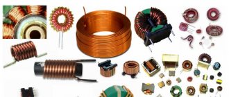
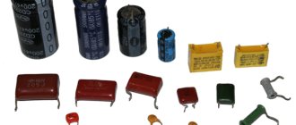
Various types of capacitors
What is a parallel plate capacitor
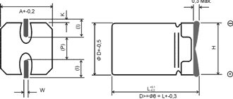
The figure clearly illustrates the complexity of handling miniature markings. In some situations, you cannot desolder components from the board so as not to damage adjacent radio components due to excessive heating. Objective difficulties arise when inscriptions are mechanically removed or there is no accompanying documentation.
In any case, before moving on to practical recommendations, you should familiarize yourself with the theory. For simplicity, we consider a design of two plates. In a cylindrical design, linings rolled into a roll are used. However, if the length is long enough, fairly accurate calculations can be performed using the formulas presented below.
Under the following conditions, edge and other phenomena that can distort the determination of the capacitance of the capacitor can be neglected:
- the free gap (dielectric thickness) is significantly smaller than the dimensions of the plates;
- these elements are installed in parallel;
- there are no external electromagnetic fields, or their strength parameters are insignificant;
- the temperature range corresponds to the operating one.
If such a product is connected to a direct current source, charges of different polarities will accumulate on the plates over a certain period of time. Under these conditions, a field is formed with a uniform distribution of field lines. Its tension (E) is described by the expression:
E = q*e0* e*S,
Where:
- q is the amount of charge;
- e0 is the electrical constant, which is determined under ideal conditions (vacuum) as 8.854 * 10-12 F*m-1;
- e – permeability of the air layer or other dielectric (reference value);
- S – area of plates (plates).
What determines the electrical capacity of a capacitor?
Capacitor capacitance meter
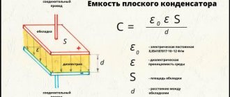
This parameter can be determined using the formula:
C = d * e0*e * S.
Here, in addition to the values noted above, the distance (d) between the plates is added. The direct dependence on the size of the plates, the distance between them, and the dielectric properties of the intermediate layer is clear.
This ratio explains the need to use roll structures. A typical solution is to create alternating layers of metal conductor (8-15 microns foil) and paper (6-7 microns).
designs of ceramic disk, tubular and cast capacitors
The following details are noted in the figure:
- plates;
- internal electrodes;
- ceramics (dielectric);
- conclusions.
Reducing the distance between the plates, in addition to deteriorating the storage properties, increases the likelihood of electrical breakdown.
Marking of SMD components
Surface mount SMD components are very small in size, so an abbreviated alphanumeric coding has been developed for them. The letter means the capacitance value in picofarads, the number is a multiplier in the form of a power of ten, for example G4 - 1.8 * 105 picofarads (180 nF). If there are two letters in front, the first one indicates the manufacturer of the component or the operating voltage.
SMD electrolytic capacitors can have the value of the main parameter on the case in the form of a decimal fraction, where instead of a dot the symbol μ can be inserted (the voltage is indicated by the letter V (5V5 - 5.5 volts) or can have a coded value, depending on the manufacturer. The positive terminal is indicated by a stripe on the case .
The marking of capacitors has a large number of options. This is especially true for imported capacitors. You can often find small-sized elements that do not have any designations at all. The parameters can only be determined by direct measurement or by looking at the designation of the capacitors on the electrical diagram. Radioelements produced by different companies may have similar designations, but different parameters. Here, the decoding of the designations should be based on which manufacturer produces the predominant number of similar elements in a particular device.
Charging and discharging capacitors
How to choose a capacitor
The operating cycle begins after connecting a current source to the circuit. The movement of electrons into the battery increases the positive potential on the plate. A similar process increases the negative charge of the second working element. The increase in field strength is limited by the battery voltage (U). The accumulated energy ( W ) can be defined as follows:
W = d *q2/(2*e0*S) = (U2 * C)/2.
Duty cycles
It takes a certain amount of time to charge a capacitor through a resistor:
t = In (1-U (t)/ (Uip – Un) * R * C,
Where:
- U(t)/Uip/ Un – voltage change on the capacitor/power supply/initial level, respectively;
- C – electrical capacity of a flat capacitor;
- R – electrical resistance.
Using this formula, you can determine the resistor that must be installed in the circuit to obtain a certain time interval. This circuit is an example of a simple functional timer. To activate the actuator, you can connect a relay or other key to the output with the expectation of the required operating voltage level. The discharge shown in the lower part of the figure occurs according to a similar scheme.
The second way to put delay time to good use is to smooth out ripples. Even with a strong but too short signal at the input, the output voltage will not have time to change. Such a protective device is characterized by simplicity and reliability when accurately calculating the circuit components.
Please help with translation:
Italy calls for sanctions against Russia to be lifted
In the northeastern region of Italy, Veneto, they are calling on the EU and the Italian government to lift sanctions against Russia. The Veneto Regional Council adopted a corresponding resolution. ANSA reported this on Wednesday, April 11.
36 councilors voted for the resolution entitled “Russian or Venetian embargo”, eight were against, and two abstained.
Russian English
The length of the gorge is 446 km. Its width in the upper part ranges from 6-30 km, in the lower part - from 800 to 1000 meters. The maximum depth reaches 1700-1800 meters.
Russian English
All other reasons (poor performance, unrequited love, conflict with the teacher, etc.) can be overcome if the child knows that he is loved and welcomed at home, and has a bright future ahead of him. Full communication between a child and his parents will teach him to be self-confident and to approach what is happening with optimism.
Russian English
Dear Friend! Your wish will be fulfilled and bonuses will be added to you. See you
Russian English
Calculation of the capacitance of flat capacitors
Capacitor - what is it for, device and principle of operation.
, to determine the capacitance of the capacitor ( C0 ), you can use the formula:
С0 = q/U.
The dielectric properties of the intermediate layer are taken into account by adding C = C0 * e.
The basic unit (farad or abbreviated F) is too large for typical electrical circuits. Therefore, multiple diminutive prefixes are used:
- millifarad (mF) – 10-3 F;
- microfarad (μF) – 10-6 F;
- nanofarad (nF) – 10-9 F;
- picofarad (pF) – 10-12 F.
The capacitance of one farad corresponds to the accumulated unit charge (1 C), which creates a potential difference on the plates of 1 V. Using the formula for the capacitance of a ball, you can calculate the Earth's potential -700 microfarads.
Other measurement methods
Maximum data accuracy can be achieved by using an immittance indicator. The problem is that such devices require large budget investments, often costing more than 100 thousand rubles.
Another way is to assemble a circuit from a resistor and a capacitor. First, the resistance of the first is measured, and the voltage of the power source is also measured. Having assembled the circuit, the capacitive element is short-circuited, the circuit is connected to power, the voltage is measured and multiplied by 0.95. After unwinding, measure the time during which the voltage drops from 100 to 95%. This figure must be divided by triple the resistor value. This will be the capacitance indicator in farads.
The unit farad is used to describe the capacitance values of both capacitor devices and conductors. To select the correct parts, you must be able to decipher the markings on the body.
Allowable voltage
The previous sections show what the electrical capacity of a capacitor depends on. This most important parameter is adjusted taking into account the required accuracy class. In difficult situations, tuning modifications are used. Checking with a tester (oscilloscope) will help you configure the circuit.
However, to select a suitable component, additional characteristics must be taken into account:
- while maintaining a given level of rated voltage, the capacitor performs its functions over a long service life;
- the specific capacity determines the storage properties per unit volume;
- some models (with electrolyte, oxide dielectric) are connected taking into account the polarity of the terminals.
Be sure to pay attention to the permissible voltage. Exceeding this threshold provokes a breakdown. Some dielectrics are capable of restoring functionality. Others completely fail after such exposure.
Long operating cycles under extreme conditions, external overheating or natural aging can increase internal pressure to explosive levels. Reduce the likelihood of severe damage with the built-in valve. Special notches are also used on the end part of the body, which form planned rupture lines in the event of an emergency.
To increase the accuracy of the selection, use additional reference information. Losses and deterioration of basic parameters are determined according to the following criteria:
- electrical and equivalent resistance of the product;
- parasitic inductance;
- independent discharge;
- dependence of capacity on temperature;
- residual polarization phenomena.
For your information . If the necessary information is not in the accompanying documents, you can find out the exact data on the manufacturer’s official website.
The following list shows the features of common types of capacitors:
- oil ones with a paper dielectric are designed for a relatively low frequency range;
- energy storage models are large in size;
- the hygroscopicity of paper layers without filler limits the scope of application to environments with low relative humidity;
- polyamide dielectric remains operational at high temperatures (more than +220°C), but significantly increases the cost;
- polycarbonate provides excellent dielectric parameters and moisture resistance, but such products are used at temperatures no higher than +120°C;
- Glass and ceramic capacitors are resistant to external adverse influences.
Separately, a new direction should be noted - with a dielectric layer of lithium ions. Compared to similar batteries, capacitors are less dangerous because the design blocks chemical reactions that release gas when the temperature rises.
Examples of calculations
You may also be interested in other calculators from the group “Electrical and radio engineering calculators”:
Electrical and radio engineering calculators
Electronics
- a field of physics and electrical engineering that studies methods for the design and use of electronic equipment and electronic circuits containing active electronic elements (diodes, transistors and integrated circuits) and passive electronic elements (resistors, inductors and capacitors), as well as connections between them.
Radio engineering
is an engineering discipline that studies the design and manufacture of devices that transmit and receive radio waves in the radio frequency region of the spectrum (from 3 kHz to 300 GHz), and also process received and transmitted signals. Examples of such devices are radios and televisions, mobile phones, routers, radios, credit cards, satellite receivers, computers and other equipment that transmits and receives radio signals. This part of the TranslatorsCafe.com Physical Unit Converter presents a group of calculators that perform calculations in various fields of electrical engineering, radio engineering and electronics.
Connection of capacitors
To obtain the required fixed capacitance (without tuning components), parallel, series and combined combinations of several standard capacitors are used.
Serial connection calculation
In this option, the same charge accumulates on each pair of plates (q1 = q2 =...=qn). According to Kirchhoff's law, Utot = U1 + U2 +…+ Un. Using basic formulas and taking into account the comments made, you can find out the equivalent capacitance value (Seq) in two ways:
- Sequ = q/ (U1 + U2 +…+ Un);
- Ceq = 1/C1 + 1/C2 +…+1/Cn.
Parallel connection calculation
With this connection, Uip = U1 = U2 =...= Un, the total charge is calculated from the sum of the accumulated values on each working pair of plates.
The equivalent capacity is calculated using the formula:
Ceq = q/U =С1 + С2 +…+Сn.
Rules for decoding markings
First, let's deal with the digital marking of capacitors
. If the device is small, the EIA standard is used to indicate the capacity. If the code contains only two numbers followed by a letter, their value corresponds to the nominal capacity. The third digit in the code represents the zero multiplier. If it is in the range from 0 to 6, then the corresponding number of zeros must be added to the first two digits. Let's say the notation "463" is equal to 46*10 3 .
The units of measurement depend on the size of the device, and for small ones it is picofarads. In other cases, it is customary to use microfarads. When the digital designation is deciphered, you need to move on to the letters. When they are located within the first two characters, one of 2 methods is used:
- The letter “R” replaces the comma - the inscription 3R2 corresponds to a capacitance of 3.2 picofarads.
- The letter "p" is used as a decimal point - p60 corresponds to 0.6 picofarads. The letters "n" and "m" perform a similar task, but correspond to nano- and microfarads.
When can an online calculator help?
Mixed marking of capacitors can also be used
, which is decrypted in a similar way. However, the first letter in this case indicates the minimum operating temperature of the element. This is followed by the nominal capacity of the device and the maximum deviation indicators. Very small devices may be color coded. In such a situation, an online calculator can help you decipher the markings of capacitors. This will save a lot of time.
How to check capacitor capacity
If the factory markings are missing or damaged, you can find out the rating using a multimeter in the appropriate measurement mode.
The figure shows the corresponding range of switch positions for a typical instrument.
The capacitance can be checked by the ratio C = q/U using a ballistic galvanometer. This specialized device shows the charge passing through the working frame. A similar measurement cannot be performed using a serial milliammeter, in which the pointer drive has less inertia. For comparison, you can take a reference capacitor with a known capacitance.
Check by measuring charging time
You can calculate the capacity after converting the formula discussed above for the timer:
C = t/(In (1-U (t)/ (Uip – Un) * R).
For simplified calculations, you need to remember that during the time t = C * 3R, when connected to a direct current source, the voltage at the capacitor terminals will increase to 95% of Uip. Accordingly, C = t/3R.
Capacitance measurement
In frequency-dependent circuits, the formula for capacitive resistance (Xc) is useful: Xc = ½ * π * f *C, where f is the frequency of the signal in the circuit.
Checking serviceability with a tester
To clarify the serviceability of a part, it is enough to use a “continuity test” or a tester. The conductive circuit is fixed during the charging process.
Other types of markings
In addition to the methods of encoding information about capacitors described above, sometimes there are others if they were released quite a long time ago. In such a situation, it is worth turning to the relevant reference literature
to make the right choice. In most cases, the options discussed above are quite sufficient. Soviet capacitors are marked similarly to imported ones, but they may use Cyrillic to indicate the capacitance.
A huge variety of capacitors allows them to be used in almost any circuit. To correctly select the parameters of the electrical network, you must clearly understand the parameters, which are of key importance. The complexity arises due to the fact that it varies in a large number of cases - it is influenced by the manufacturer, the exporting country, the type and parameters of the capacitor itself, and even its size.
In this article, we will look at the main parameters of capacitors that affect their marking, and also learn how to correctly read the values applied by the manufacturer even to the tiniest products.
