P-channel serviceability
The serviceability of the p-channel element is checked using the same method as for the n-channel type. The difference is that the red probe must be connected to the minus of the multimeter, and the black wire must be connected to the plus of the device.
Thus, the following conclusions can be drawn regarding field-effect transistor components and test procedures:
- Field elements of the MOSFET variety are widely used in radio electronics, technology and other areas related to practical electronics;
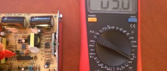
- Checking the performance of transistor elements is most convenient and best done using a multimeter - by following a certain step-by-step method;
- Testing p-channel and n-channel transistor components is carried out using the same methods, but it is necessary to reverse the polarity of the multimeter leads.
Field effect transistor components are very popular in various technical and electronic devices. But for high-quality and durable operation, periodic checking of mosfet transistors using a multimeter is required. By following all the methods described above, you can save significant financial costs associated with replacing and repairing field-effect transistors.
Main causes of malfunction
The most common reasons for a triode element in an electronic circuit to fail to operate are as follows:
- Break in the transition between components.
- Breakdown of one of the transitions.
- Breakdown of the collector or emitter section.
- Power leakage under voltage.
- Visible damage to the terminals.
Characteristic external signs of such a breakdown are blackening of the part, swelling, and the appearance of a black spot. Since these shell changes occur only with high-power transistors, the issue of diagnosing low-power ones remains relevant.
Semiconductor elements are used in almost all electronic circuits. Those who call them the most important and most common radio components are absolutely right. But any components do not last forever; overvoltage and current, temperature violations and other factors can damage them. We will tell you (without overloading with theory) how to check the performance of various types of transistors (npn, pnp, polar and composite) using a tester or multimeter.
Safe work rules
Mosfets are very vulnerable to static electricity. In this case, a breakdown may occur. To prevent this from happening, you need to remove it through testing.
When soldering, a situation is possible where the heat entering the transistor will lead to its damage. In this case, it is necessary to provide heat dissipation. To do this, just hold the transistor terminals with pliers during the soldering process.
Field workers are widely used in modern electronic devices. When a breakdown occurs, you need to know how to check the mosfet. It is possible to find out if it is working if you use a multimeter for this.
Element testing
There are several ways to test a triac for functionality. For the simplest, you will only need a multimeter, and for more complex measurements, an autonomous power supply or test circuit.
With the help of a tester, testing occurs using knowledge based on the operating principle of a triac. Diagnostics with a multimeter will not be able to determine all the characteristics of the element, but it will be quite sufficient for initial performance testing.
A simple test can be done using a light bulb and a battery. To do this, one terminal of the battery is connected to the control and operating terminals of the triac, and the second to the base of the light bulb. The element's output is connected to the central contact of the illuminator. In this case, the transition must be open, then the light will light up.
Checking with a tester
A device of any type of action is suitable for carrying out tests, but it is necessary that the value of the current it produces is sufficient to switch the element. Therefore, it would be more preferable to use an analog device. For example, to test the BTB12-800CW tester, you will need to provide a current of about 30 mA, and for the BTB16-700BW this figure should be 15 mA.
You will also need to pay attention to the condition of the battery in the tester. In a digital device, the battery replacement icon should not be displayed on the screen, and in an analog device, when the probes are short-circuited to each other, the arrow should point to zero
The essence of the measurement comes down to checking the transitions of the device. To do this, the tester switches to resistance testing mode at the smallest range. It is best to perform the check in the following sequence:
- Test leads are connected to the power terminals of the triac T1 and T2. If the radio element is working properly, then the multimeter should show an infinitely high resistance.
- The polarity of the applied signal at the working terminals changes. To do this, the measuring probes are rearranged. The resistance must also be high.
- The operating terminal T1 or T2 and the control electrode G are briefly connected.
- Again the junction resistance between T1 and T2 is measured. It should change in one direction. So, for BTB12-800CW it will be about 50 Ohms.
- The polarity changes. In this case, the junction impedance should be high, which corresponds to the absence of reverse breakdown.
Using a schema
There are many different schemes used by radio amateurs to test the performance of a triac. But it is better to use a universal circuit that can test any element of the thyristor family, for example, BTB16-700BW. It does not require configuration and works immediately after assembly. In order to assemble it, you will need the following elements:
- Resistors R1—R4 470 Ohm, R4—R5 1 kOhm.
- Capacitors C1 and C2 - 100 µF x 6.5 V.
- Diodes VD1, VD2, VD5 and VD6 - 2N4148; VD2 and VD3 - AL307.
A KRONA type battery can be used as a power source.
The essence of the measurements comes down to the following actions: switch S3 is moved to the upper position, as a result, power is supplied to the device. After this, by briefly pressing the S2 button, current is supplied to the control output of the element.
If the BTB16-700BW is working, then its junction should open, which will be signaled by the VD3 LED. Then the switch is set to the middle position, the LED should go out. In the next step, S3 is switched to the down position and button S2 is pressed. The result of these actions will be the lighting of the VD4 LED. This behavior of the triac will allow us to declare with 100% confidence that it is working.
Checking a triac is not so difficult, especially if you use a tester, although it is better to assemble a special circuit. But it is worth noting that due to the high sensitivity of triacs to switching current, it is better to use pointer instruments as multimeters.
Features of design, storage and installation
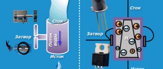
An n-channel type transistor consists of a silicon substrate with p-conductivity, n-regions obtained by adding impurities to the substrate, and a dielectric that insulates the gate from the channel located between the n-regions. The pins (source and drain) are connected to the n-regions. Under the influence of a power source, current can flow from source to drain through the transistor. The magnitude of this current is controlled by the insulated gate of the device.
When working with field-effect transistors, it is necessary to take into account their sensitivity to the effects of an electric field. Therefore, they must be stored with the terminals short-circuited with foil, and before soldering, the terminals must be short-circuited with a wire. Field-effect transistors must be soldered using a soldering station, which provides protection against static electricity.
Before you start checking the serviceability of the field-effect transistor, you need to determine its pinout. Often, on an imported device, marks are applied that identify the corresponding terminals of the transistor. If there is no pinout on the device, you must look it up in the documentation for this device.
Where to begin?
Before checking any element with a multimeter for serviceability, be it a transistor, thyristor, capacitor or resistor, it is necessary to determine its type and characteristics. This can be done by marking. Once you know it, it won’t be difficult to find a technical description (datasheet) on thematic sites. With its help, we will find out the type, pinout, main characteristics and other useful information, including replacement analogues.
For example, the scanning on the TV stopped working. Suspicion is raised by the line transistor marked D2499 (by the way, a fairly common case). Having found a specification on the Internet (a fragment of it is shown in Figure 2), we receive all the information necessary for testing.
Figure 2. Specification fragment for 2SD2499
There is a high probability that the datasheet found will be in English, no problem, the technical text is easy to understand even without knowledge of the language.
Having determined the type and pinout, we solder the part and begin testing. Below are the instructions with which we will test the most common semiconductor elements.